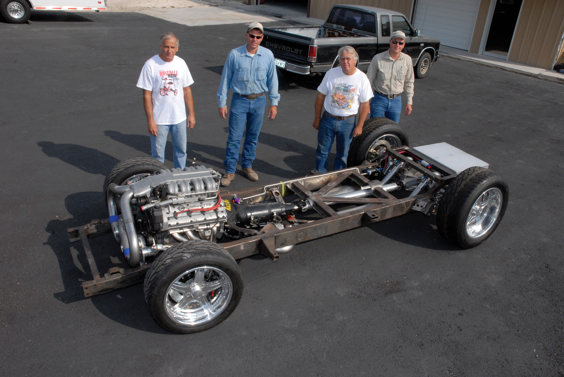
“What’s going on right now with this truck is probably one of the most difficult parts of the overall buildup,” commented Cimtex Rods’ Darrell Cimbanin. “Getting everything to fit inside and underneath this highly modified 1956 Chevrolet Cameo half-ton chassis, like the exhaust and fuel systems, for example, requires a lot of thought and careful planning, not to mention the actual fabrication process, which is very time consuming!”
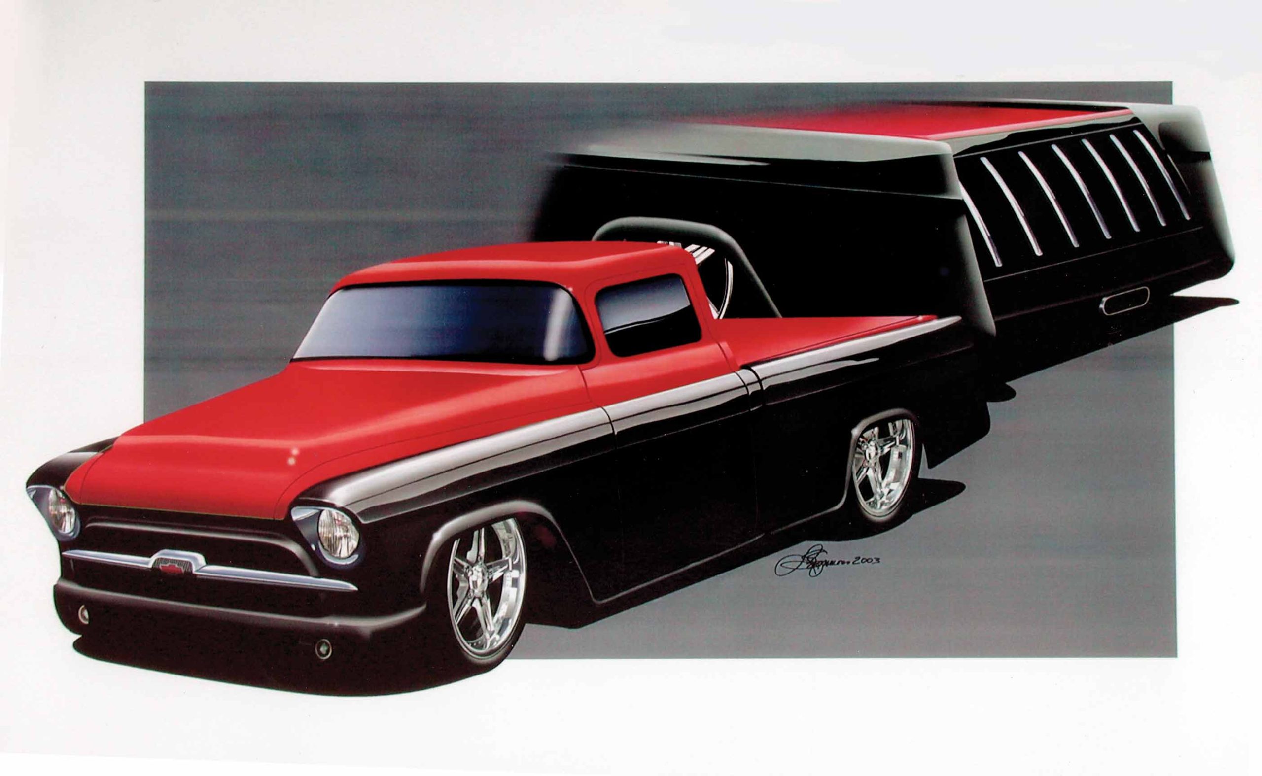
But it’s the details that make a winner, and Tim and Darrell Cimbanin are well aware of that fact. This is undoubtedly the reason why the Cimbanins’ previous effort, an angle-chopped, candy tangelo-hued, 1955 pro touring Chevrolet stepside won so many awards, such as the Goodguys Truck Of The Year (2002-2003), Boyd’s Pro’s Pick at both Scottsdale and Columbus, and Daryl Starbird’s Fine Nine award in Tulsa, Oklahoma, not to mention being featured in a total of six magazines. Furthermore, Tim and Darrell’s ’55 was also selected as a feature vehicle at SEMA for two years running.
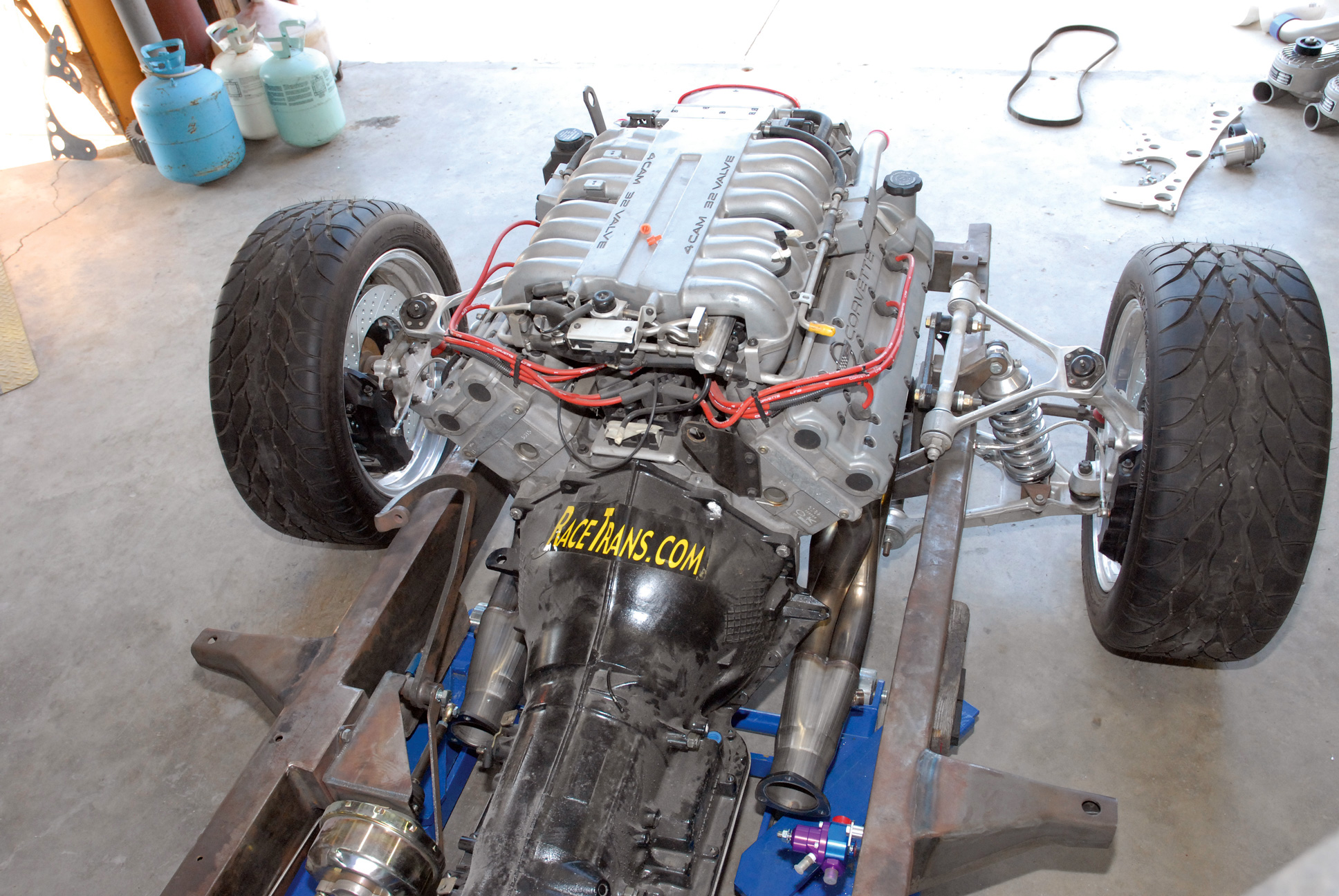
In part 6 of Cimtex Rods Super Cameo buildup, we covered the fabrication of both the engine and transmission mounts for our Corvette ZR1 and Jimmy G./GM 4L80E four-speed electronic overdrive transmission. In this installment, we’re going to cover the fabrication of our Cameo’s exhaust and fuel systems, two crucial ingredients in the overall makeup of a total chassis package.
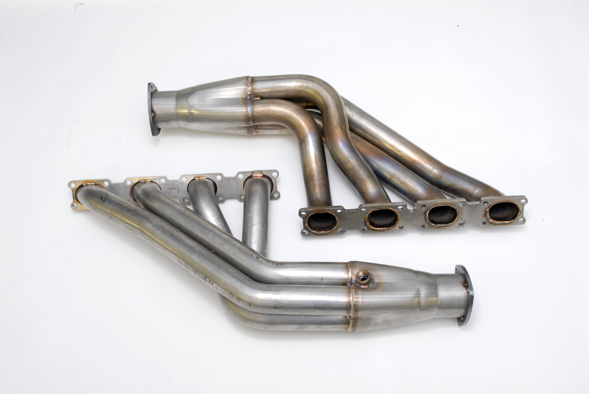
“When we reached this point, we were agonizing over two things: the headers and the fuel tank. Due to the fact that the ZR1 four-cam Corvette engine was a limited-production (performance) option, not everyone in the automotive aftermarket felt inclined to build headers for these cars. We called quite a few of the top-name companies in the automotive aftermarket exhaust systems business, and the answer was always the same. Then, just as we were about to give up and fabricate a set of our own headers, we got a tip that Stainless Works (in Chagrin Falls, Ohio) manufactured a set of equal-length, stainless-steel four-tube headers for the Corvette ZR1. We contacted General Manager Al Nowe, and I guess that you could say the rest is history.”
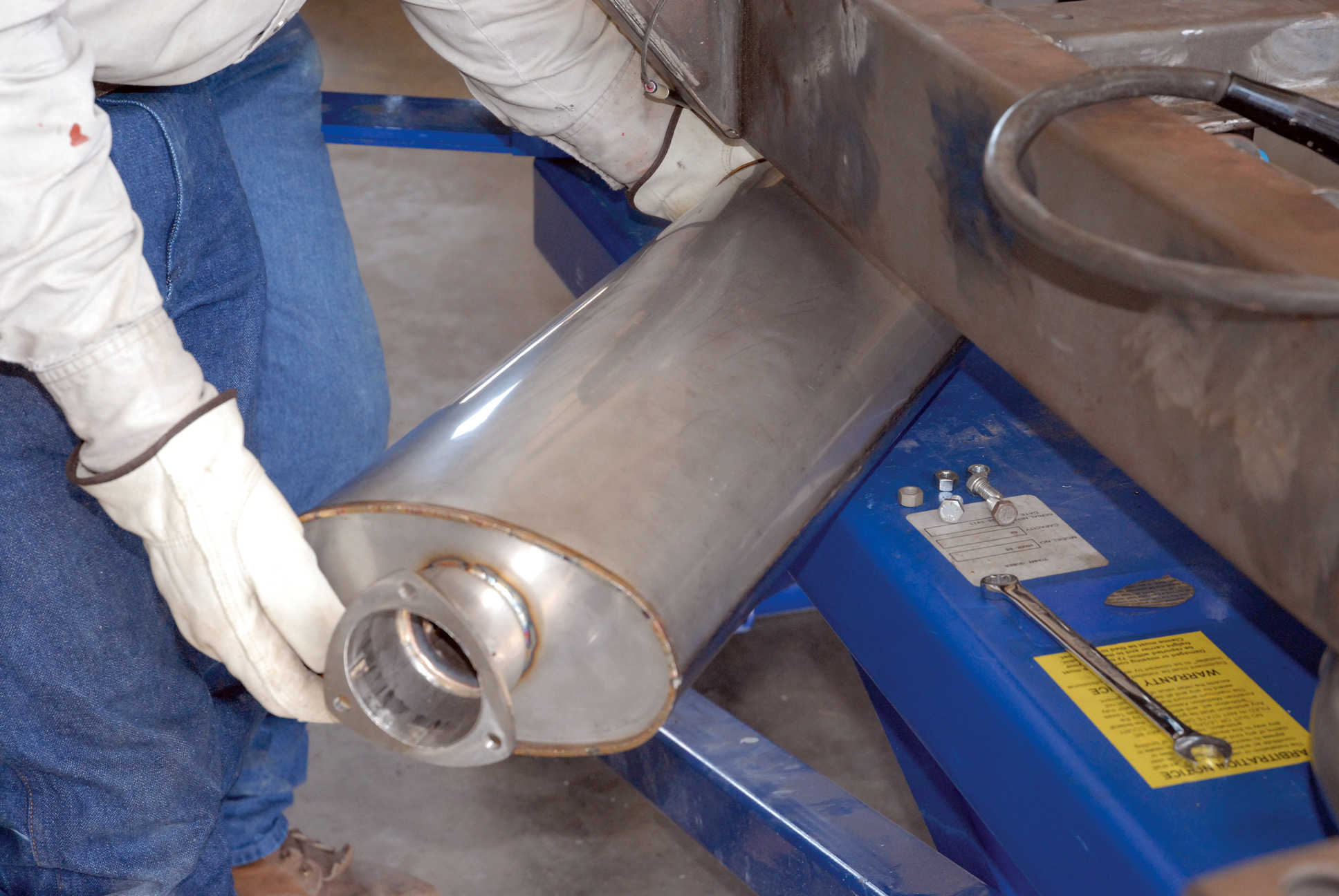
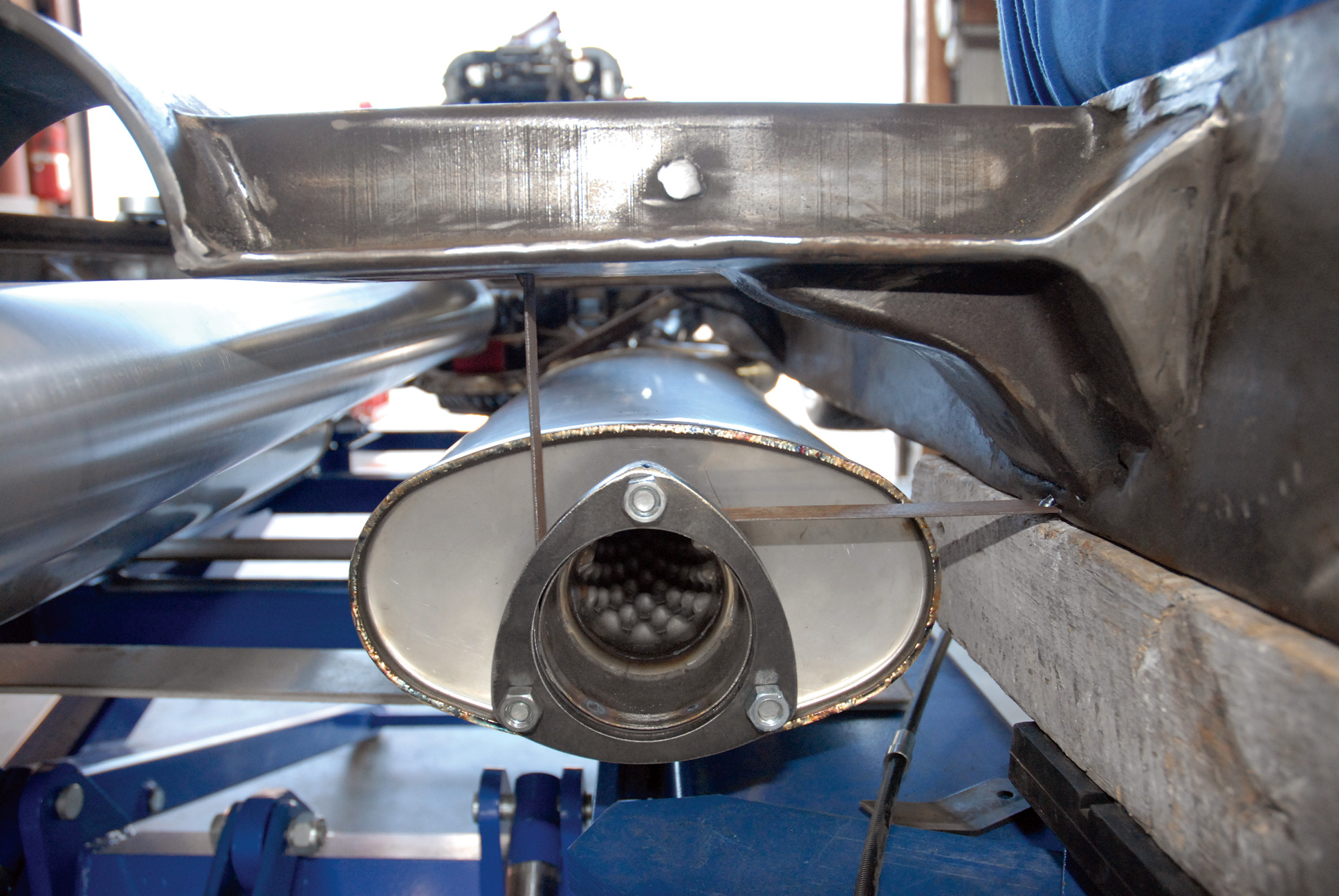
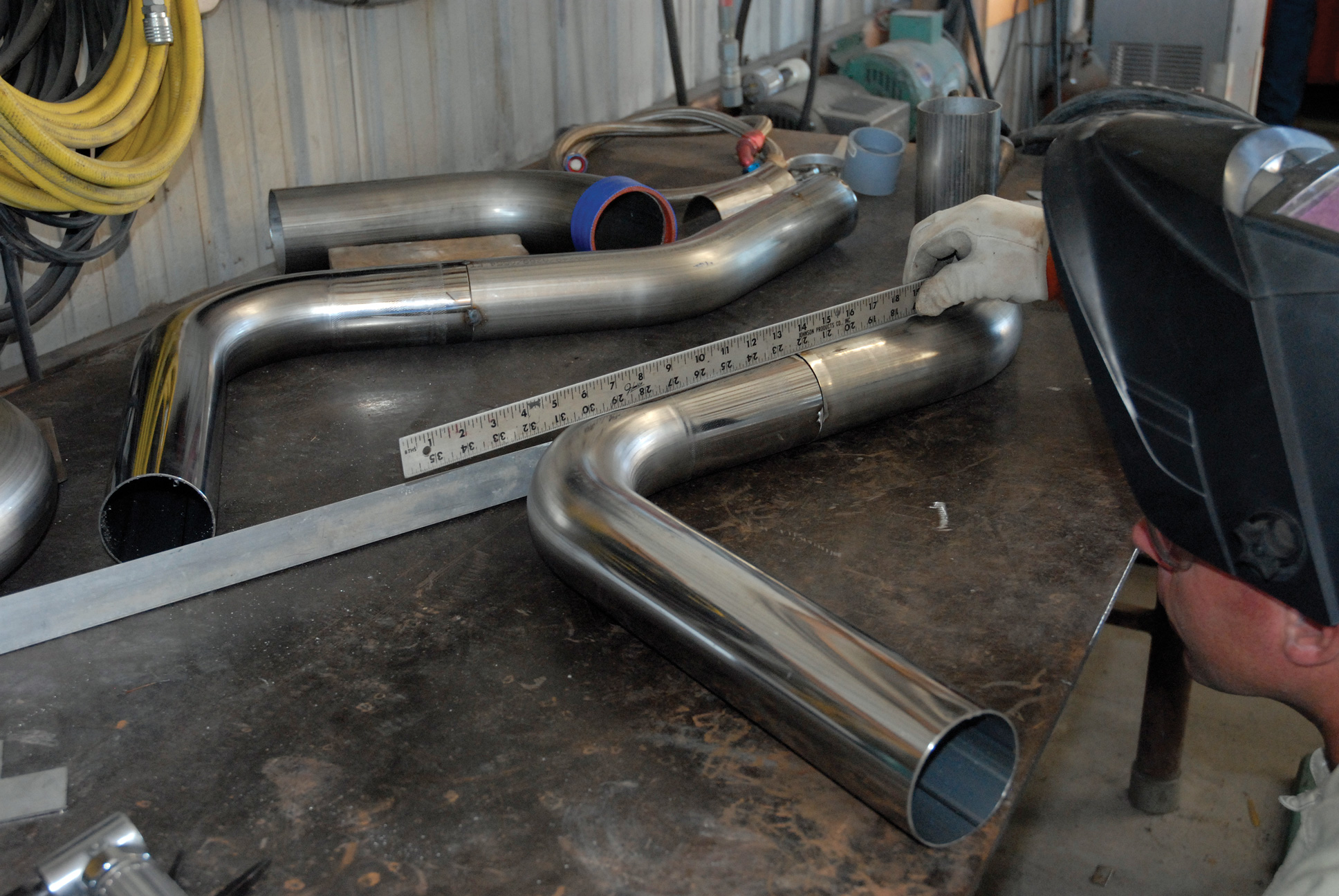
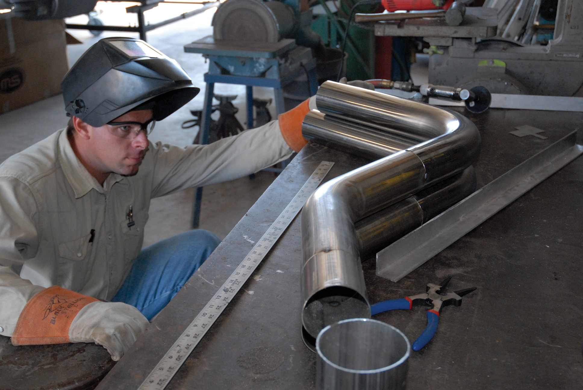
Stainless Works tuned up the Cimbanins’ Super Cameo program with a pair of ZR1 Corvette headers (part No. ZR1CORV3/8HDR), which features laser-cut, 3/8-inch-thick header flanges; 2-inch, 16-gauge stainless steel primary tubes, and a 3-inch collector complete with O2 sensor provisions (which will be equipped with a pair of Denso O2 sensors). They’ll also be using a pair of custom-sized, “turbo style,” 5x9x24-inch stainless steel mufflers featuring a 2-1/2-inch core with 3-inch center inlet and a 3-inch center outlet. Also on the Cimbanins’ toy list was a set of Stainless Works high-temp silicone grommets, weld-on Trick Hangers (part No. TH3W) and a V-Band coupling kit (part No. VBC3). The guys also opted for one of the Stainless Works 3.00-inch rod builder kits, featuring a series of four 45-degree elbow bends, four 90-degree elbow bends, four 180-degree elbow bends and four 14-inch “sticks” of stainless steel exhaust tubing (part No. RB3).
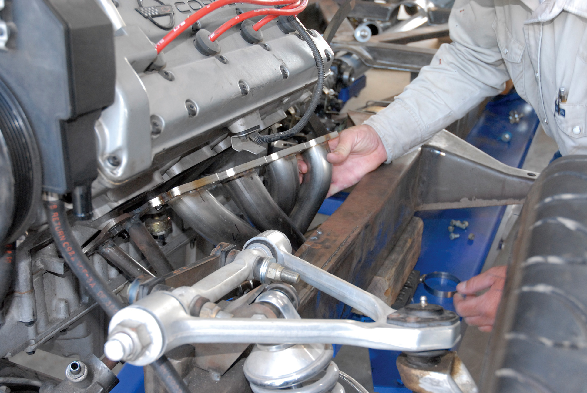
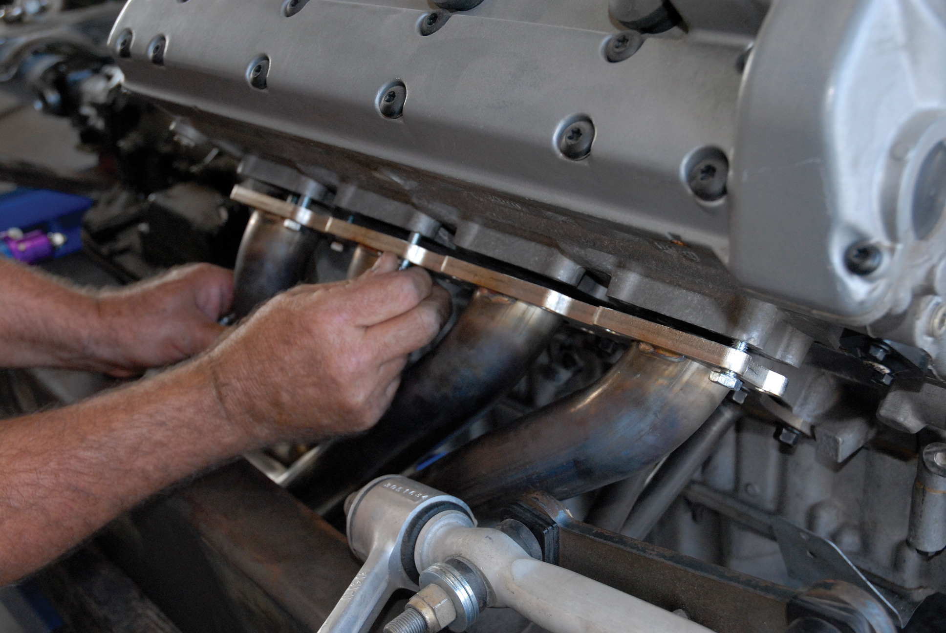
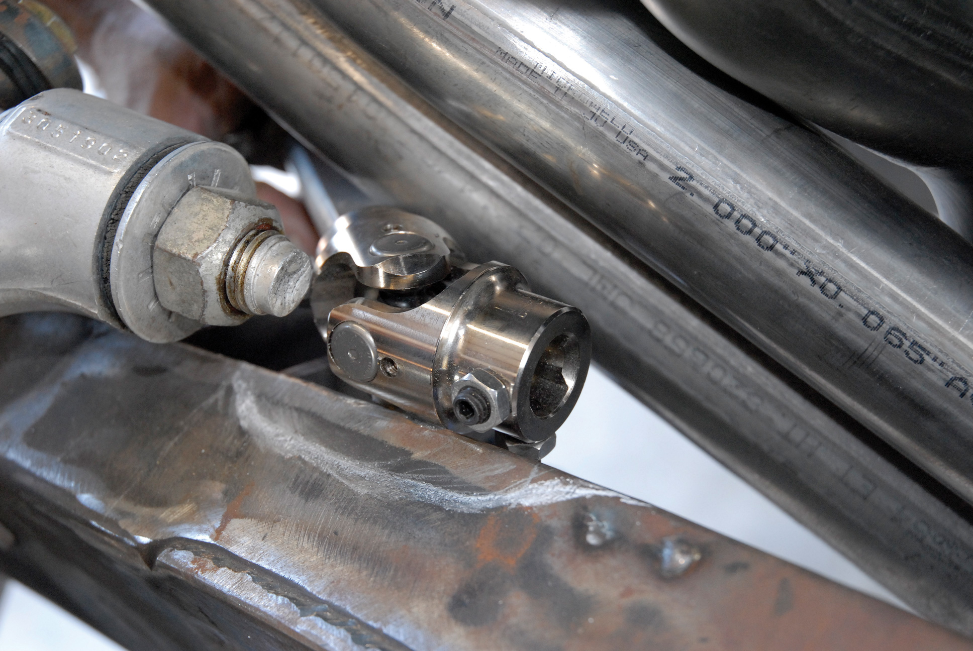
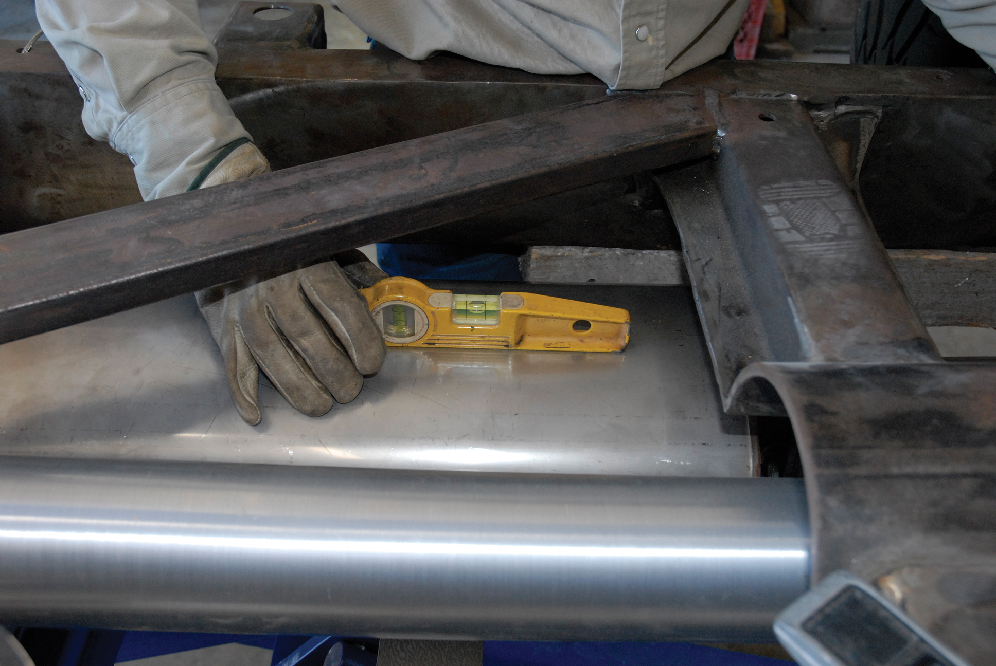
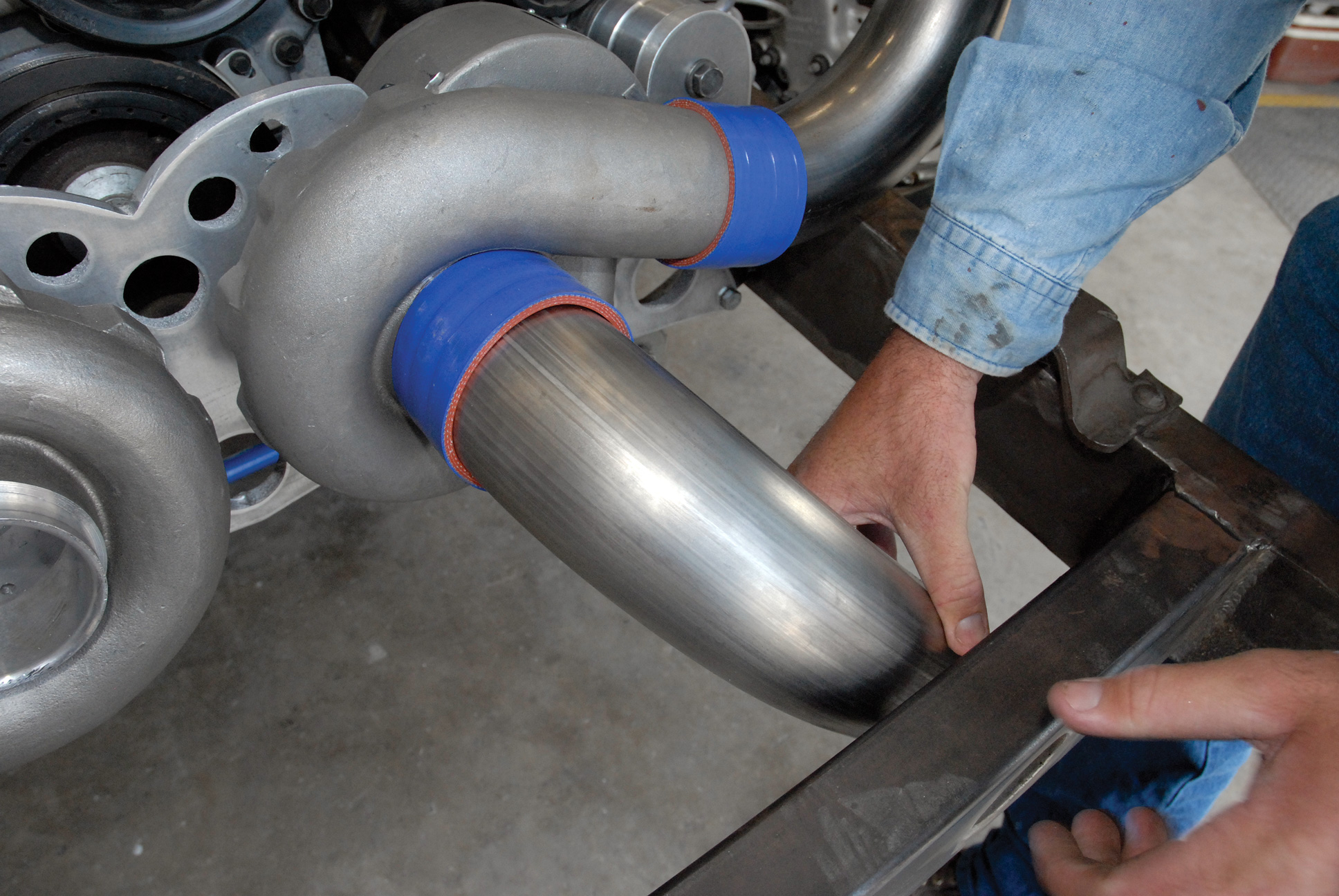
Armed with headers and a lot of high-quality stainless steel exhaust tubing, it appeared that team Cimtex was well on its way to fabricating a great exhaust system. But would the Corvette ZR1 headers fit inside the highly modified 1956 Chevrolet Cameo chassis? “They [the headers] dropped in without any problem. In fact, with the exception of the steering shaft extension running from the Corvette rack-and-pinion-steering assembly up the driver’s side of the chassis, it was a near perfect fit. What we’re going to have to do is slightly dimple the top rail of the chassis to provide the necessary steering shaft clearance.”
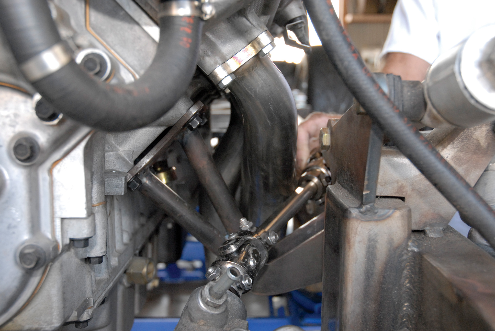
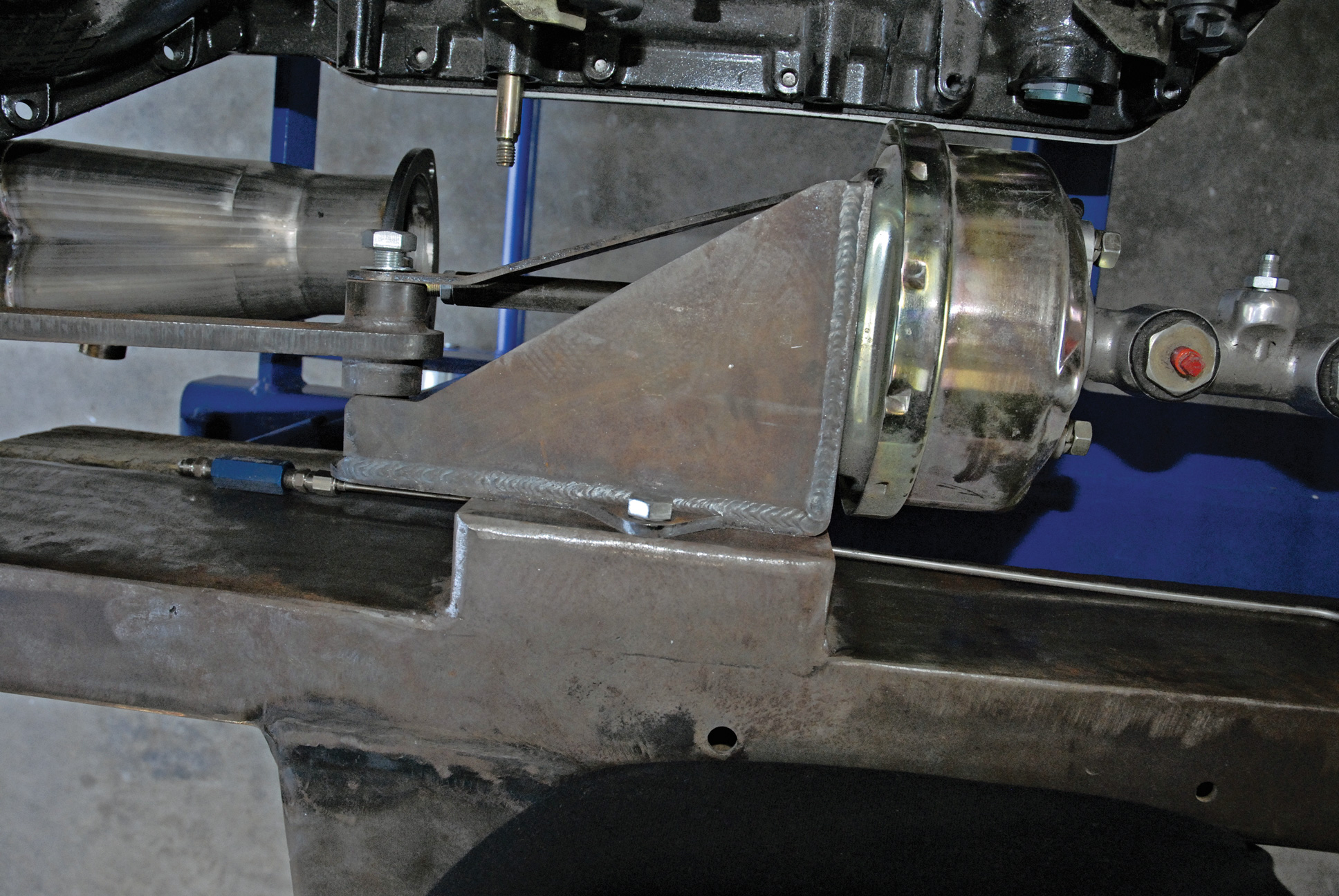
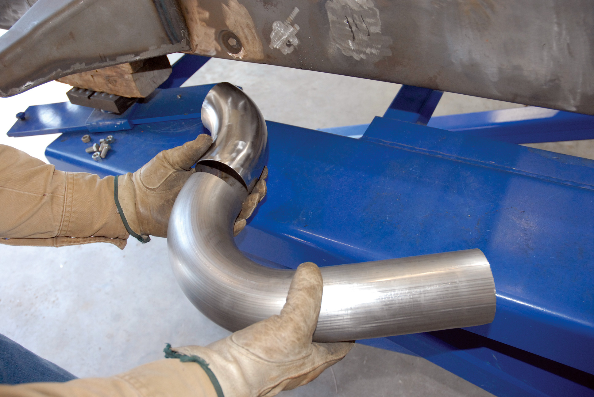
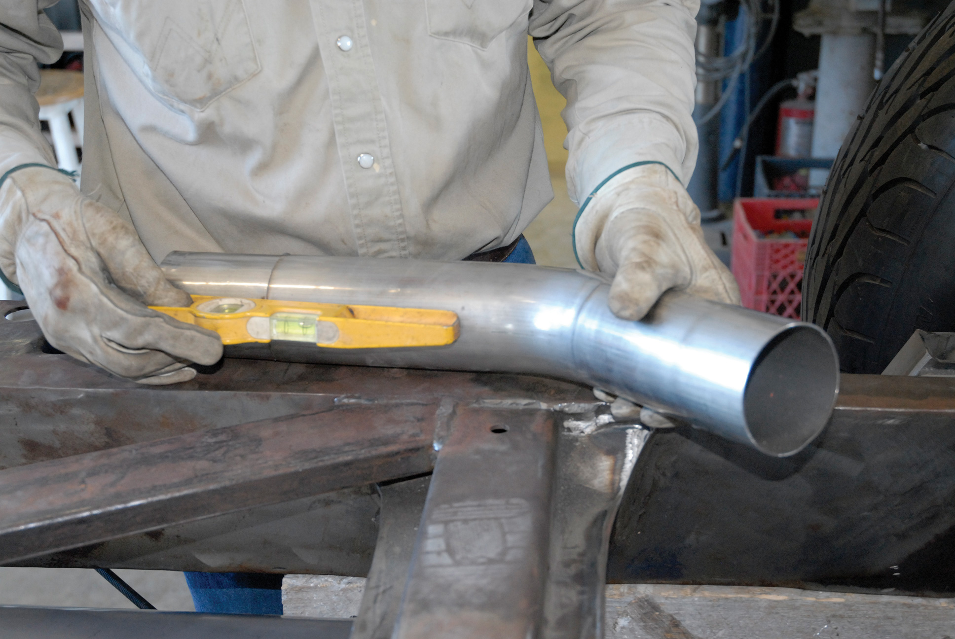
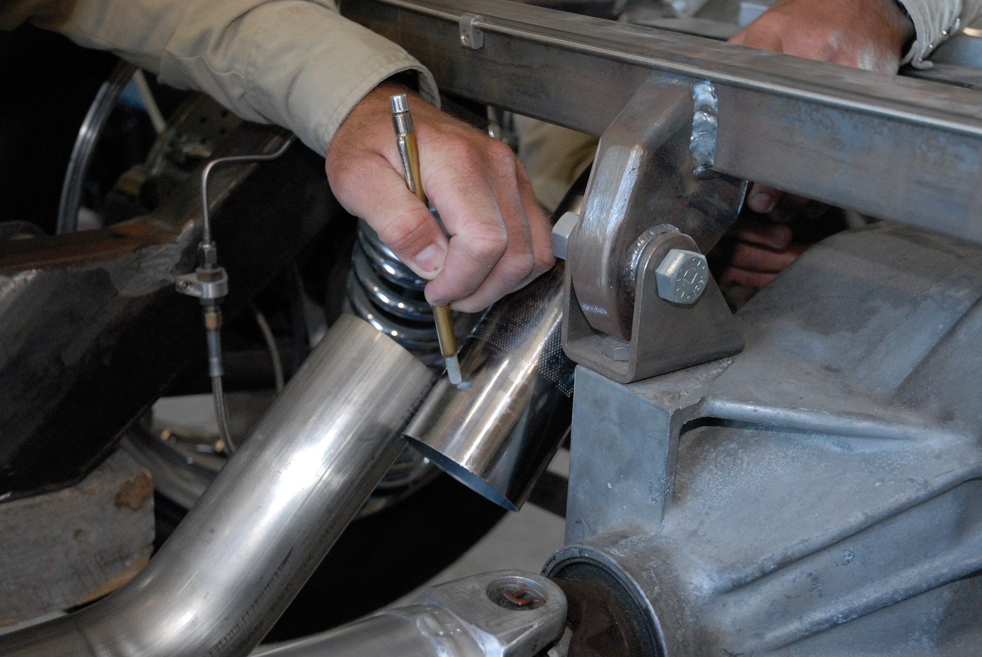
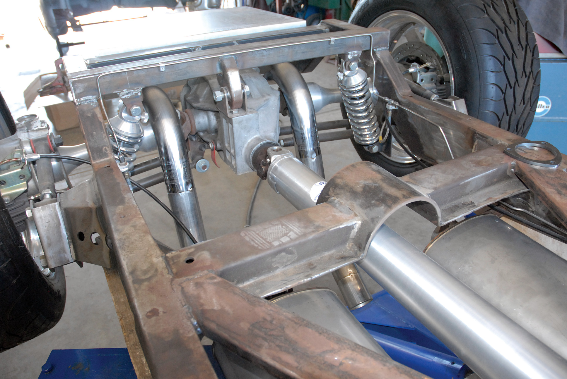
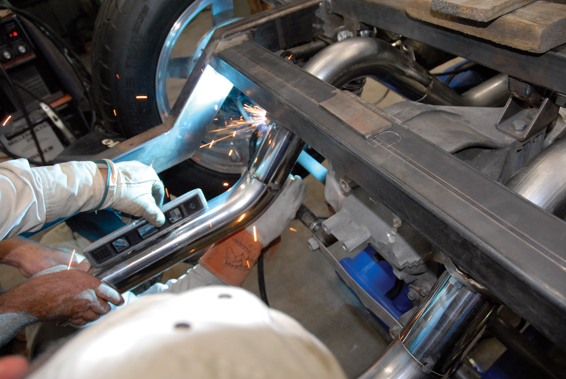
When it came to the previously installed power brake booster and pedal assembly, it was another story. One quick look revealed that the pedal assembly was in the way of the exhaust. Cimtex fabricators Dennis and Jerry Danek came up with a design using an assortment of bends, cut from the Stainless Works tubing provided, which snaked around the power brake booster at a 15-degree angle running underneath the lower framerail, and then back inside the chassis. To maintain visual symmetry, an identical setup was fabricated for the passenger’s side. Then both sides were joined to the 5x9x24-inch Stainless Works mufflers, which were located 1-1/8 inches inboard from the framerails. The framerails were temporarily strapped and tack welded to the Cameo’s front and rear crossmembers.
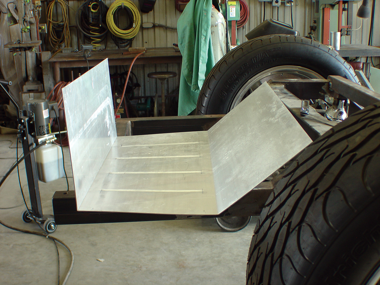
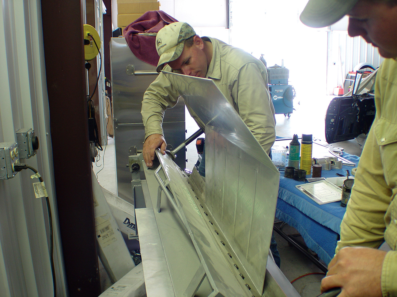
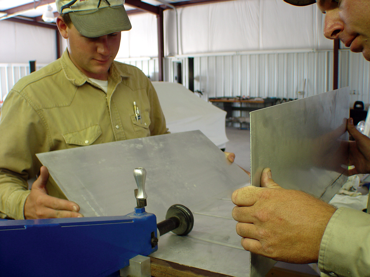
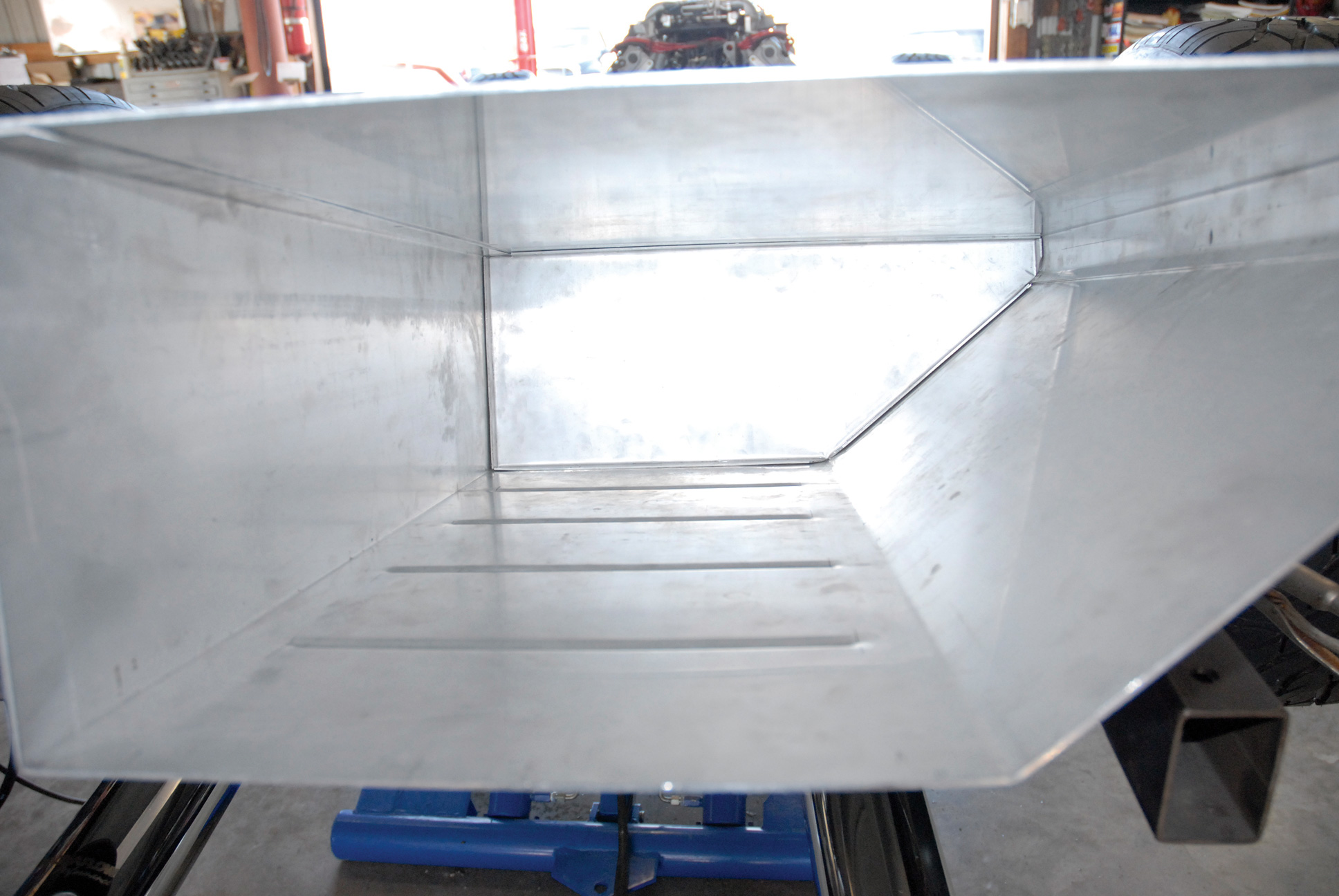
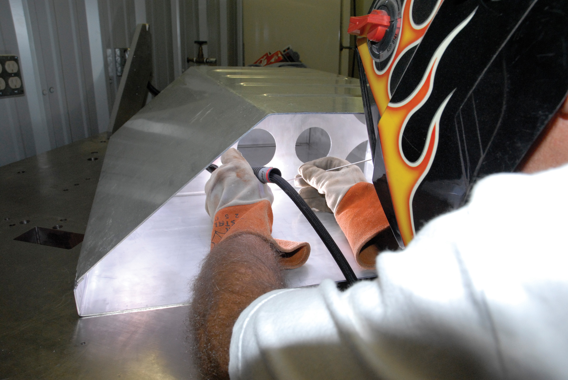
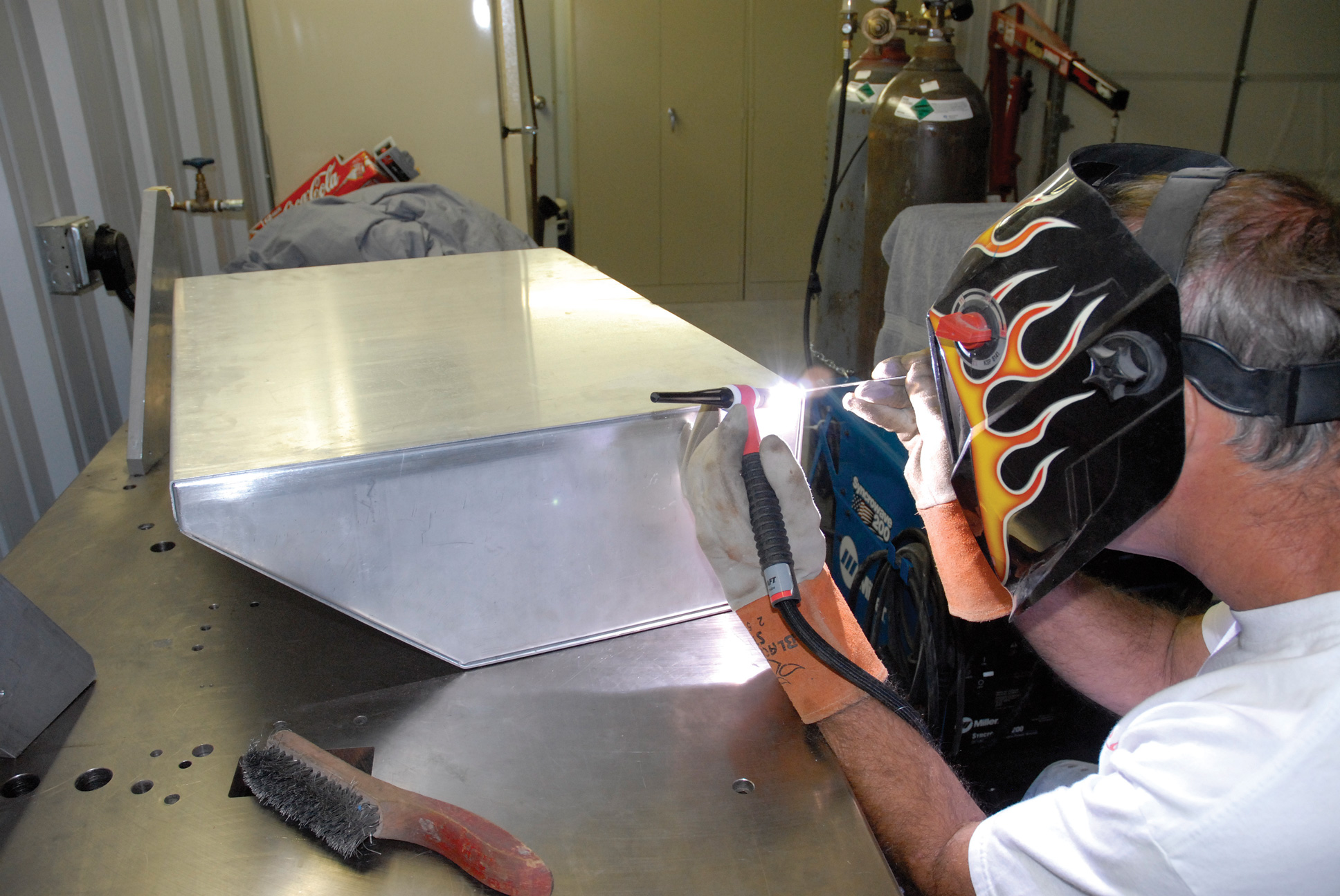
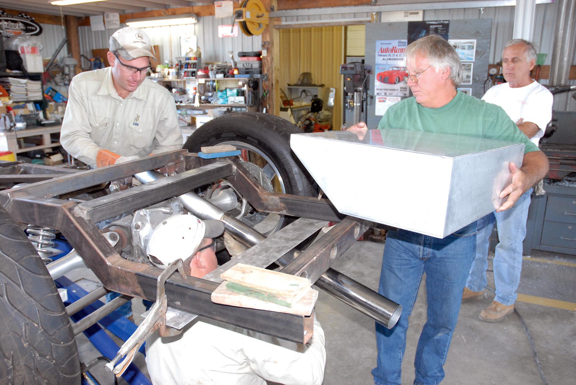
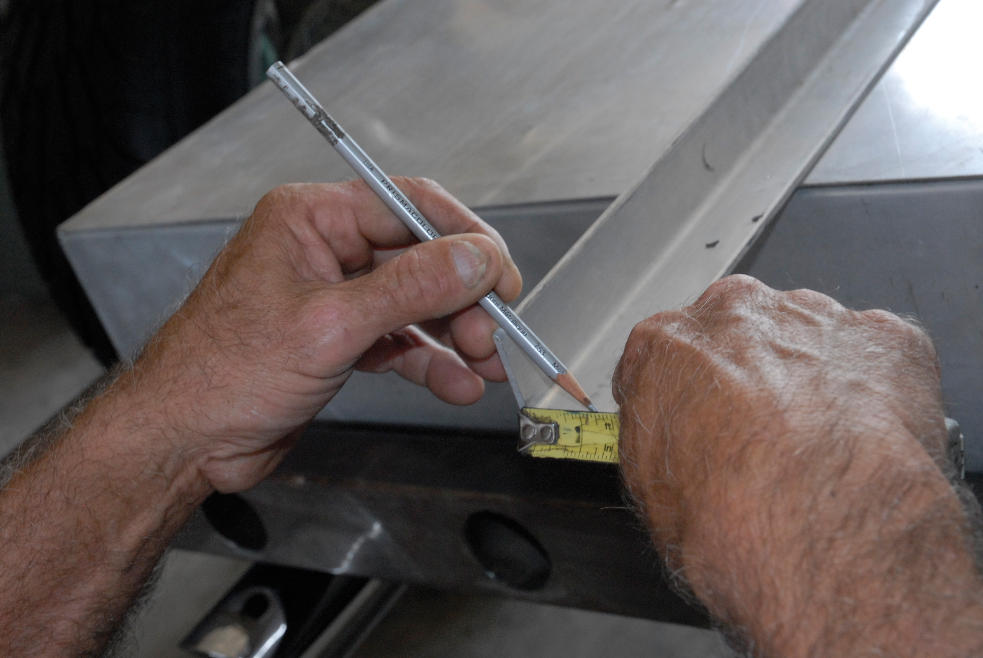
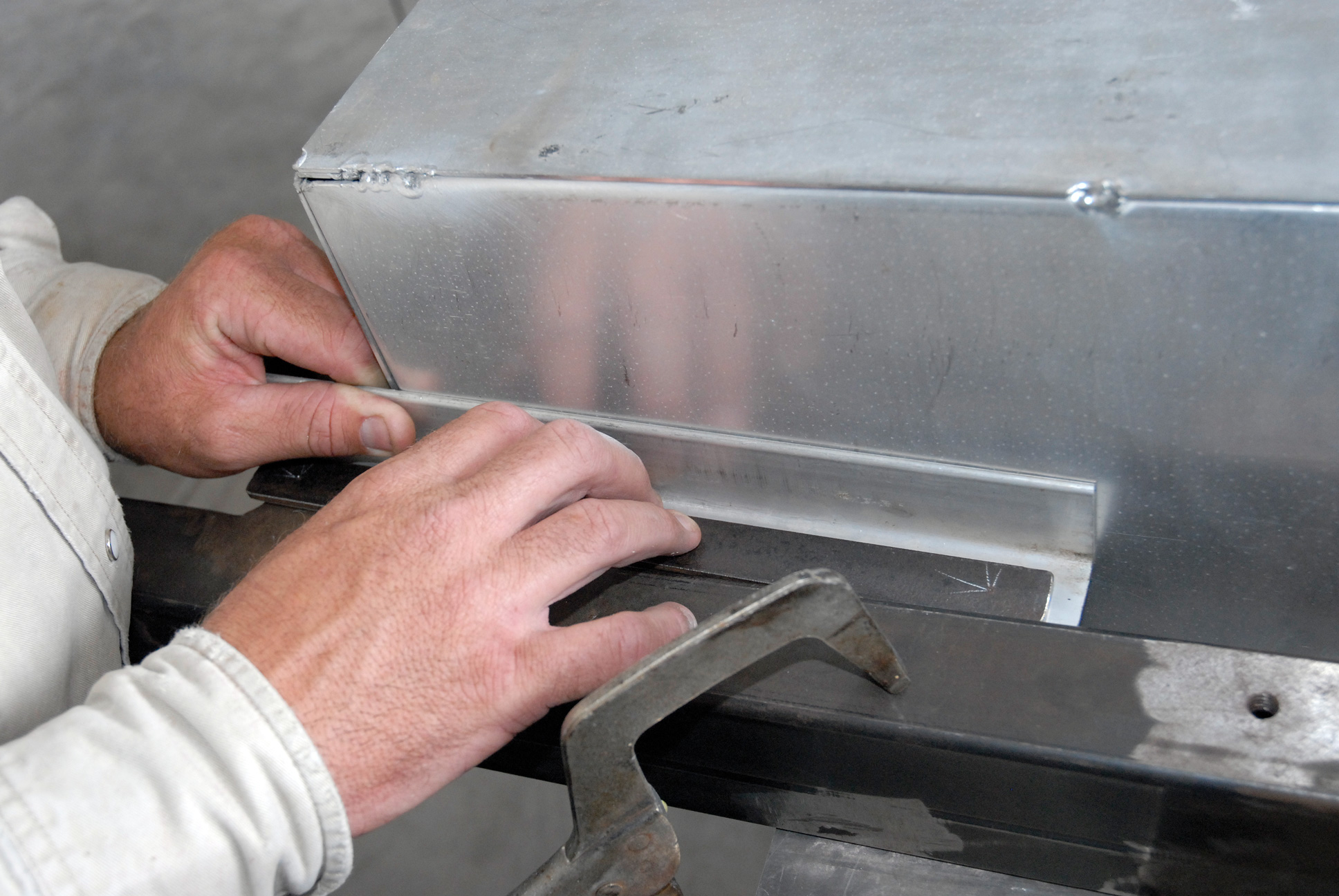
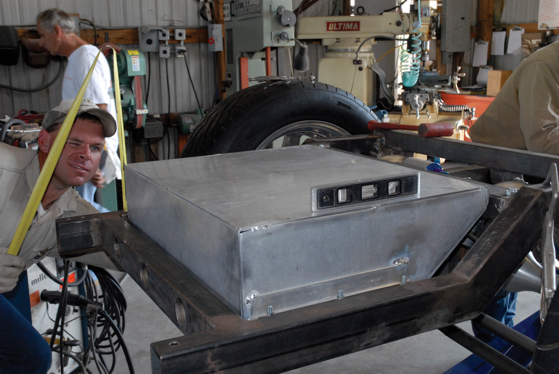
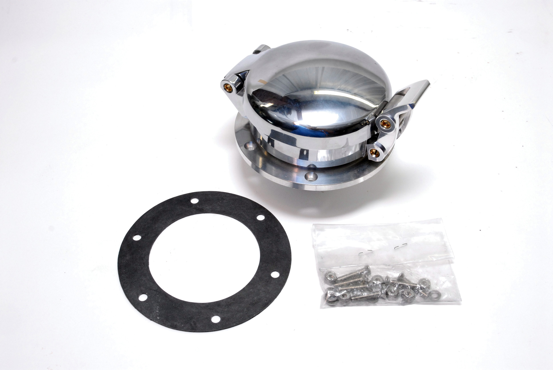
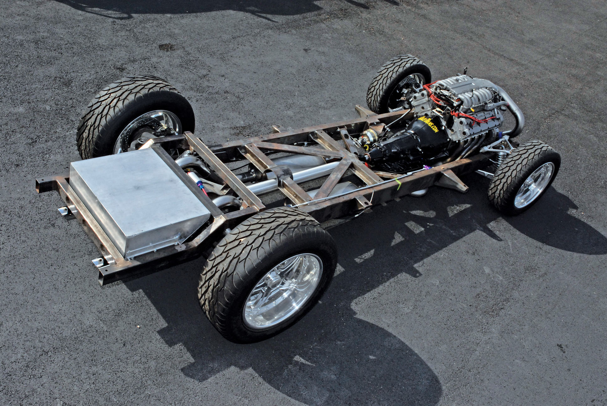
At this juncture, the gas tank would need positioning in order to be able to finish up the back half of our exhaust system. However, there was one slight problem—it never arrived! Wanting to run a fuel cell, we had previously contacted a fuel cell manufacturer and explained what was needed—a fuel cell to fit within the 29-7/8×16-inch opening at the back of our chassis. We figured this could be easily handled. Wrong! While initial calls of inquiry showed promise, as our construction and editorial deadlines loomed heavily upon us, all telephone calls and e-mails went unanswered. Anticipating a major problem in the production schedule, Darrell Cimbanin came up with Plan B. He fabricated a specially shaped, 45-degree-angle (to clear the C4 Corvette IRS), 20-gallon fuel tank folded out of a single sheet of .085-inch aluminum, measuring 27×20.5×8 inches. This tank would be ribbed at the bottom for added strength and internally baffled to control cavitation. The new tank will also feature an electronic fuel sending unit and 1/2-inch outlet and 1/2-inch return lines. Once completed, this tank will be anodized semigloss black, and clearcoated for durability, and it will feature a bed-accessed Shelby Automotive roll pin competition gas cap like those used on 289 and 427 Cobras.
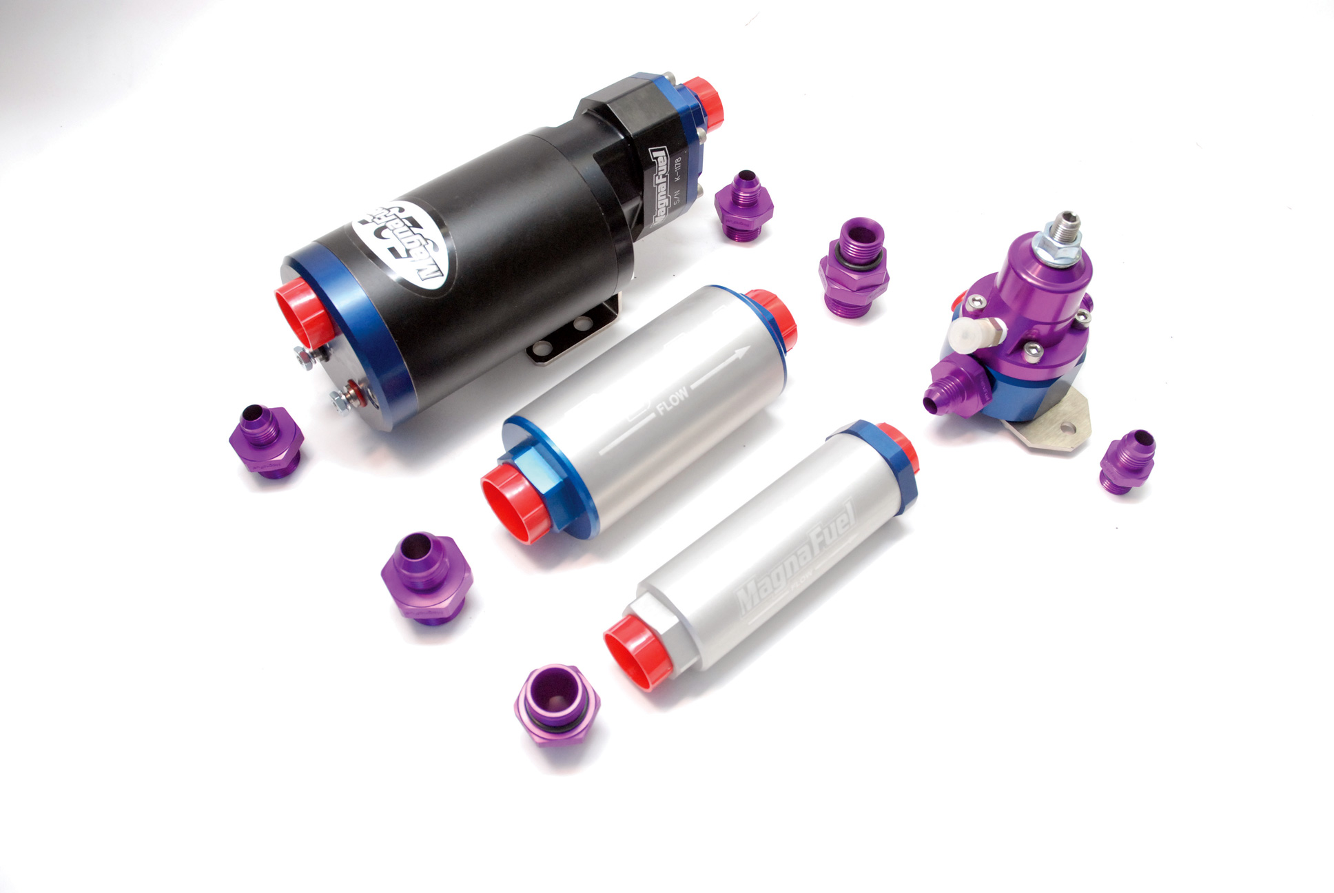
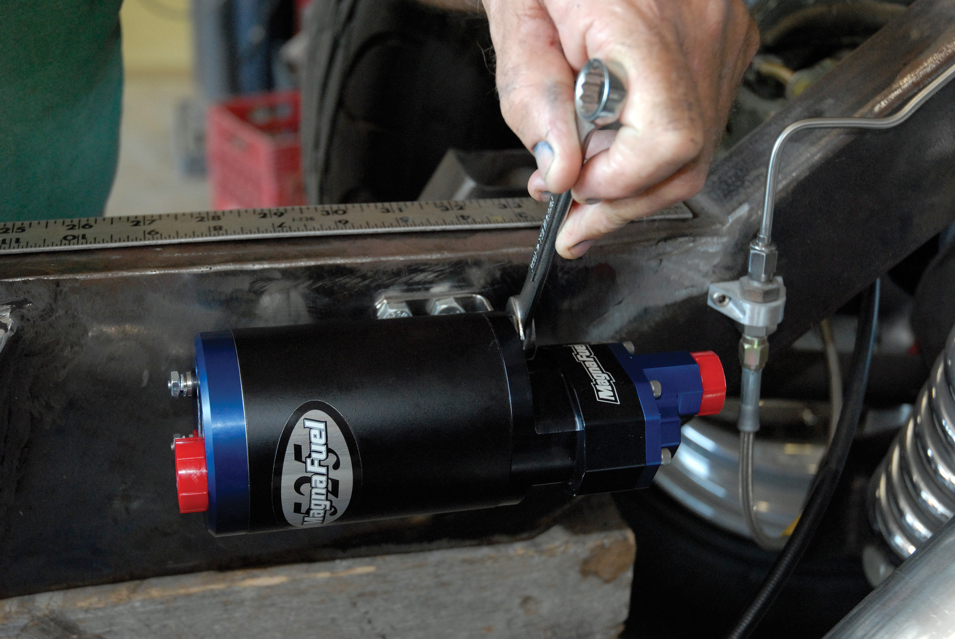
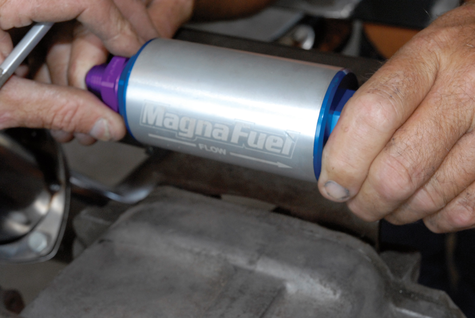
Of course, we also needed a good fuel system to accommodate our twin Powerdyne supercharged Corvette ZR1, so we contacted the folks at Colorado Springs, Colorado’s MagnaFuel and arranged to have one of its MP-4302 ProTuner 525 electronic fuel pumps shipped, along with one of its M-9925-B standard bypass regulators and MP-7009 and MP-7010 74-micron medium inline and small inline filters and assorted couplings.
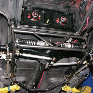
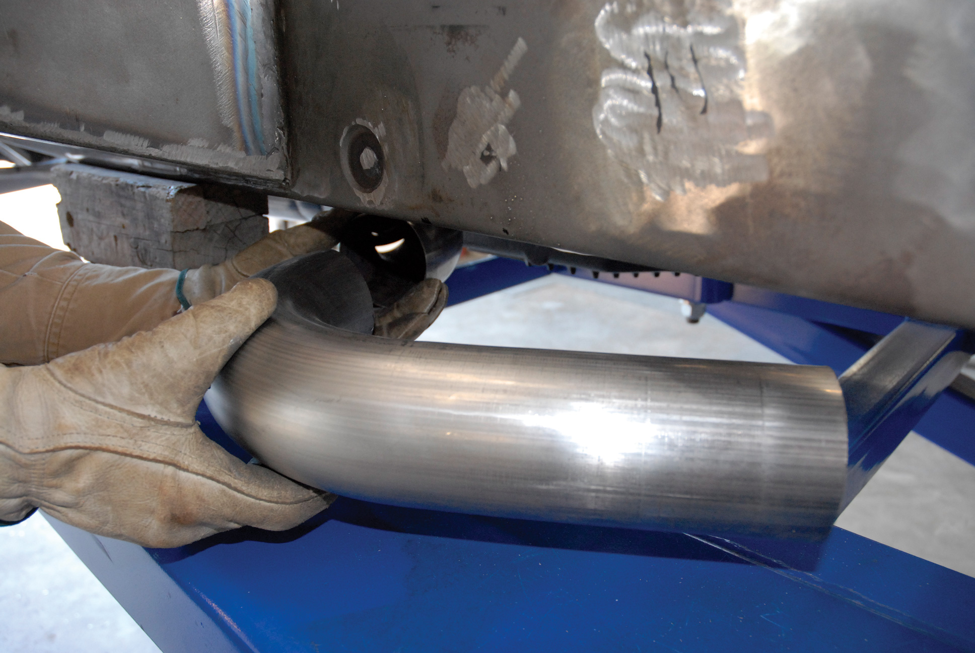
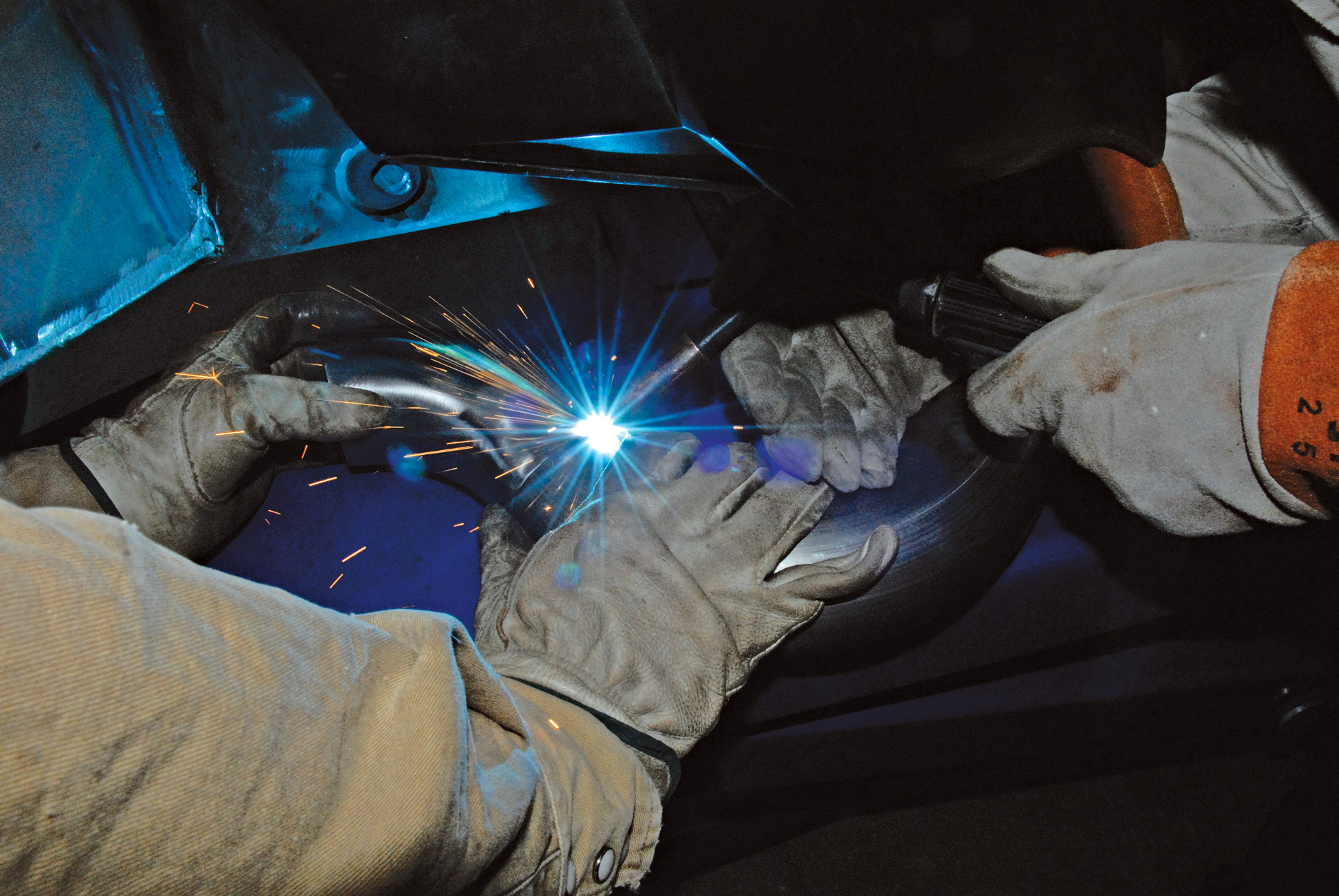
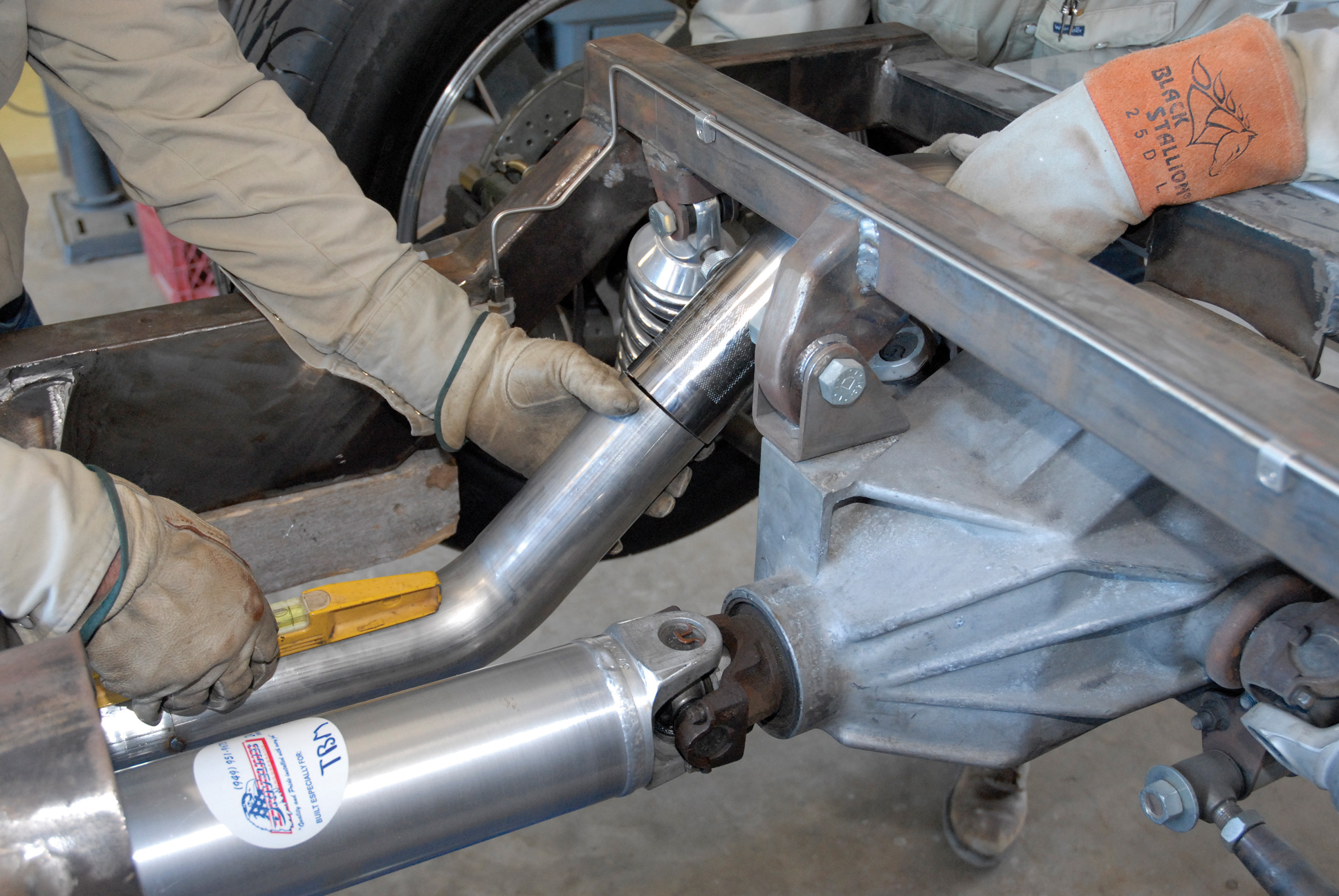
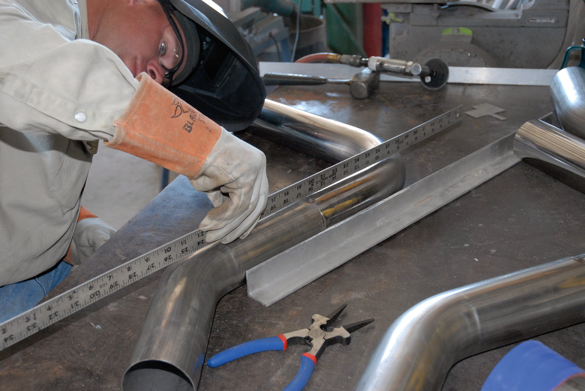
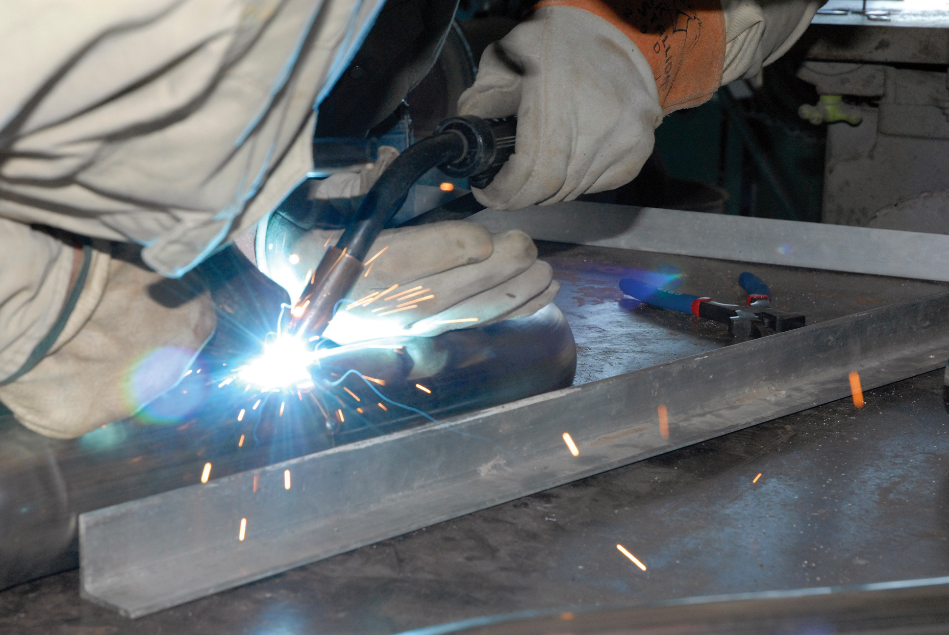
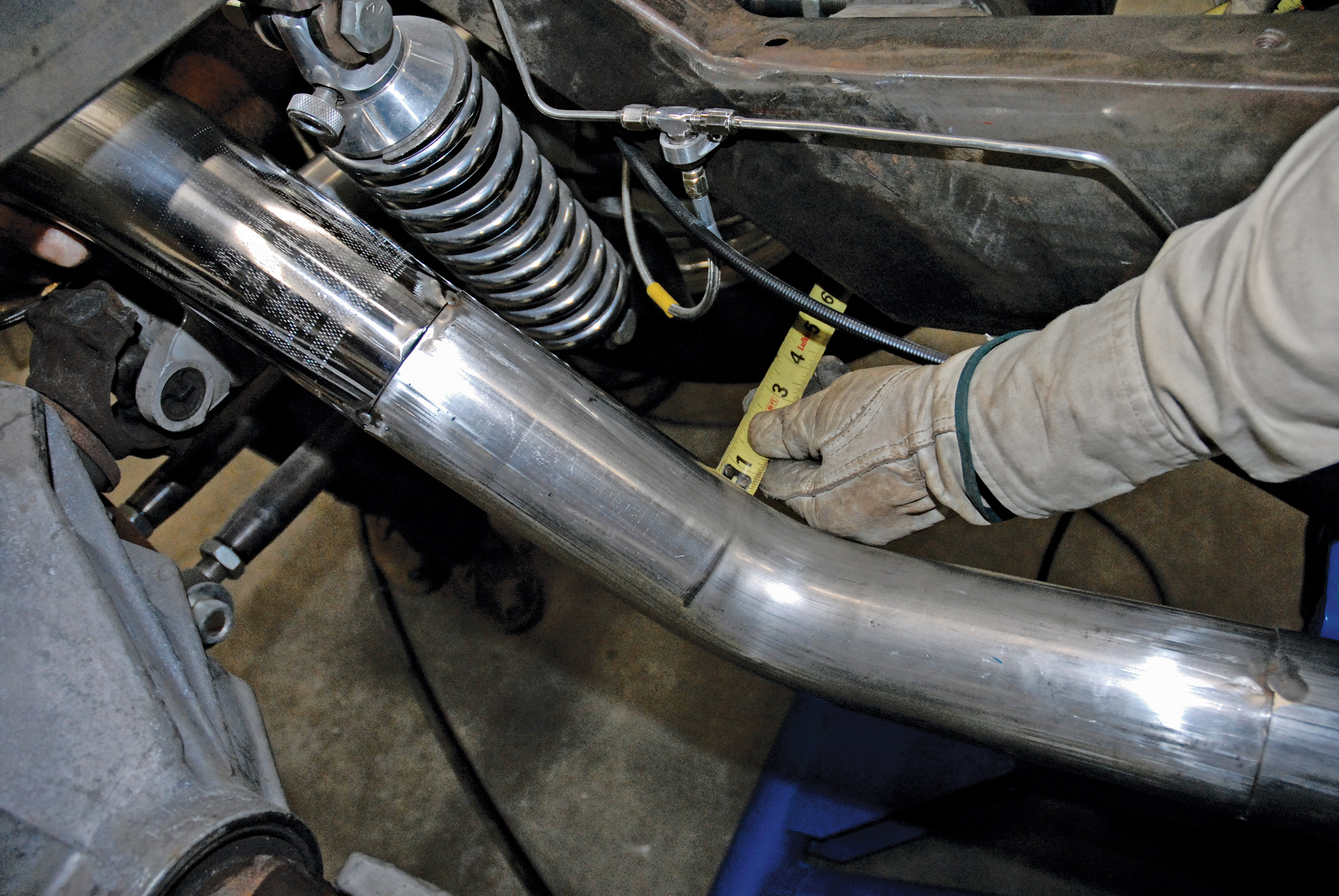
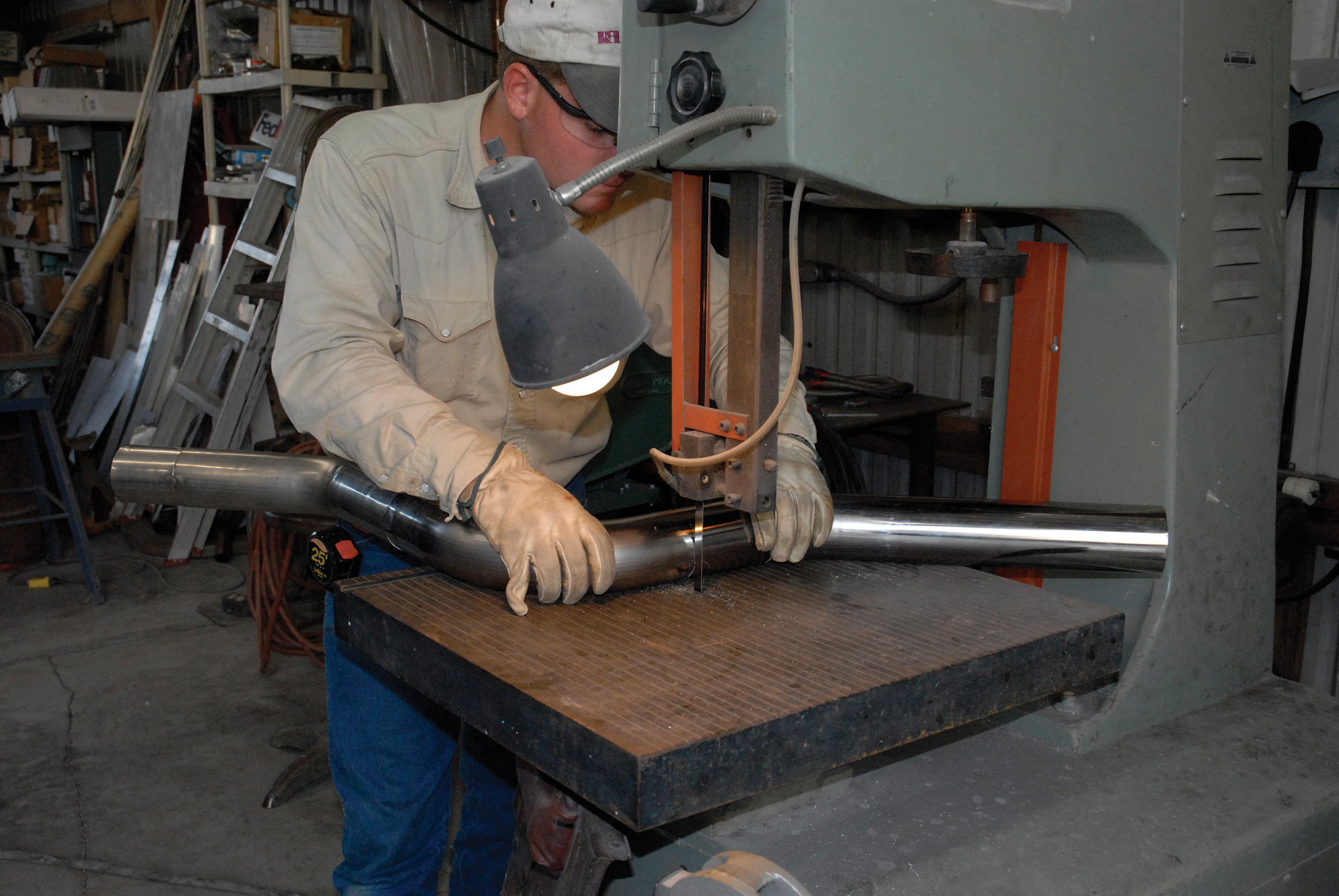
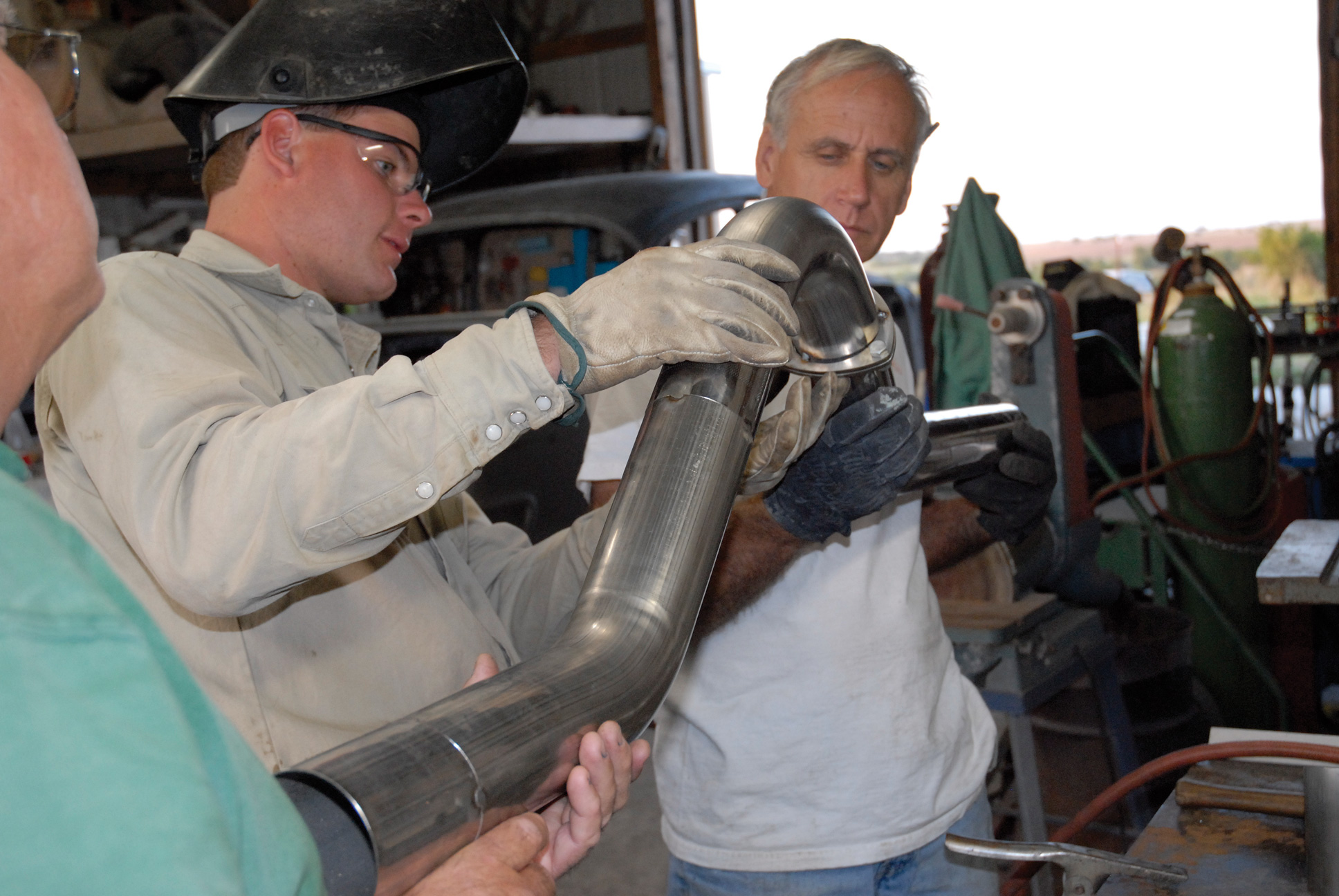
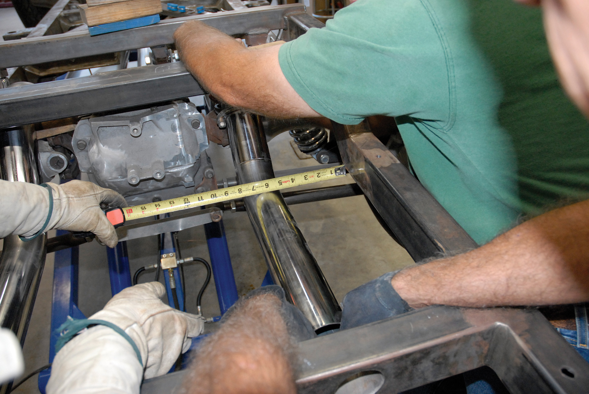
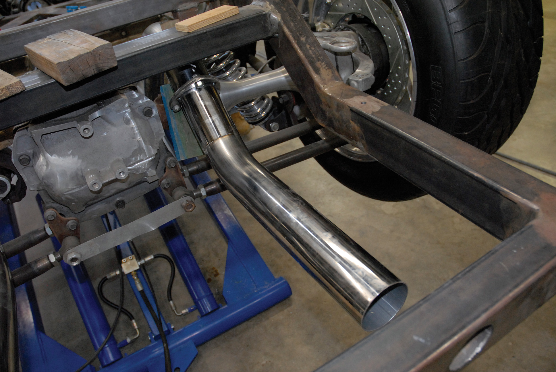
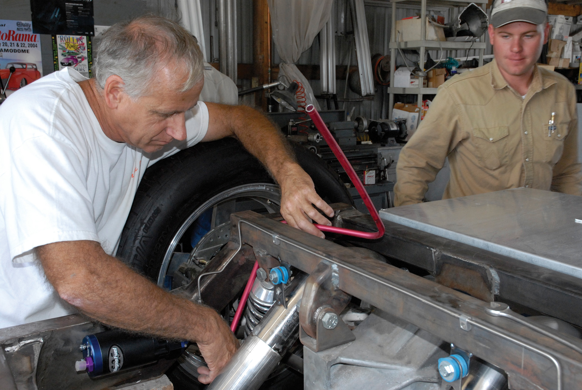
With the new fuel tank securely clamped in place, the brothers Danek continued fabricating the exhaust risers, or rear sections, of the exhaust system. Obviously, with the Corvette independent rear suspension, space is at a premium. Then, too, you must also take into consideration all important suspension travel while snaking the exhaust over the Corvette half shafts and under the rear crossmember. Obviously that called for a little creativity and required the most amount of fabrication time.
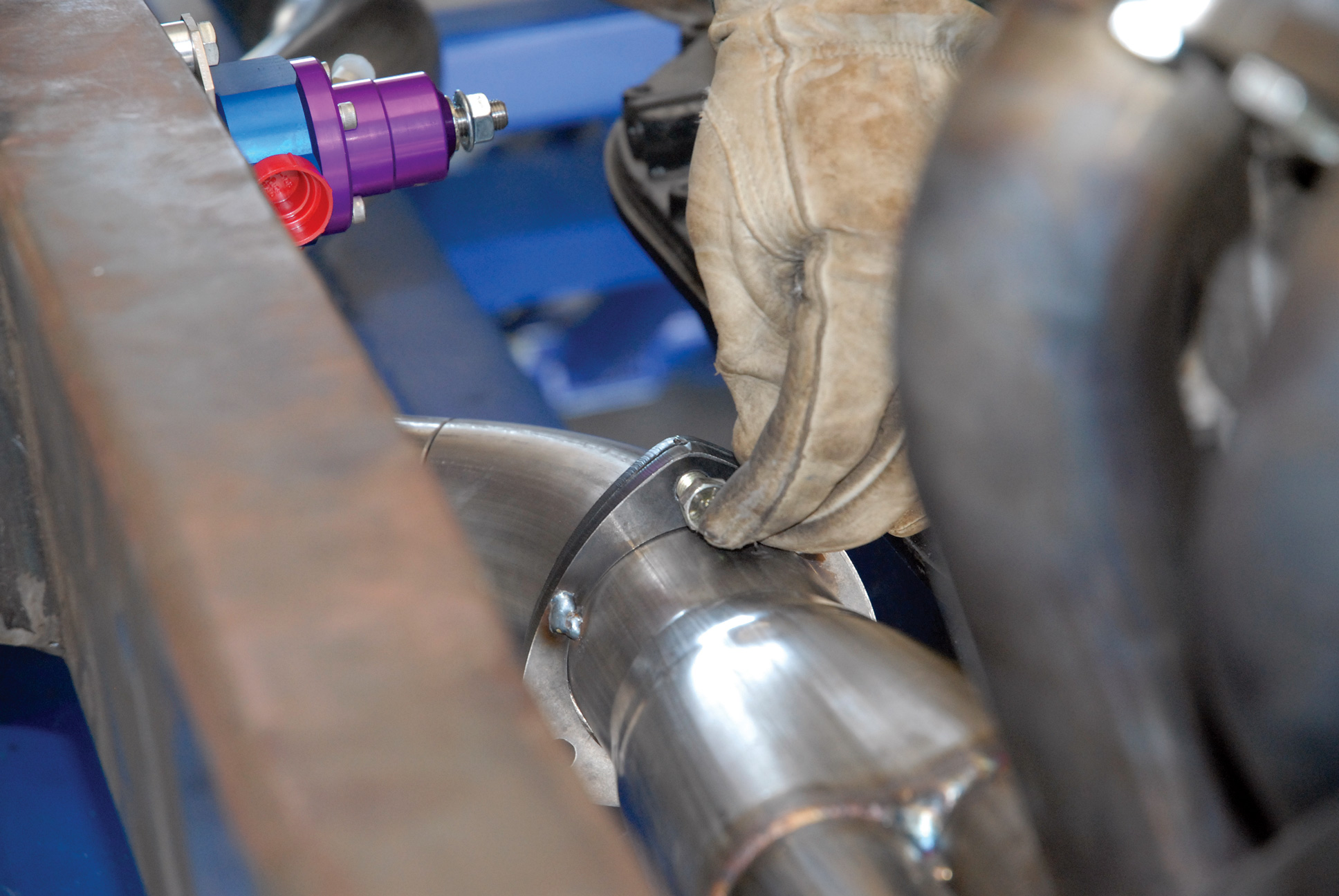
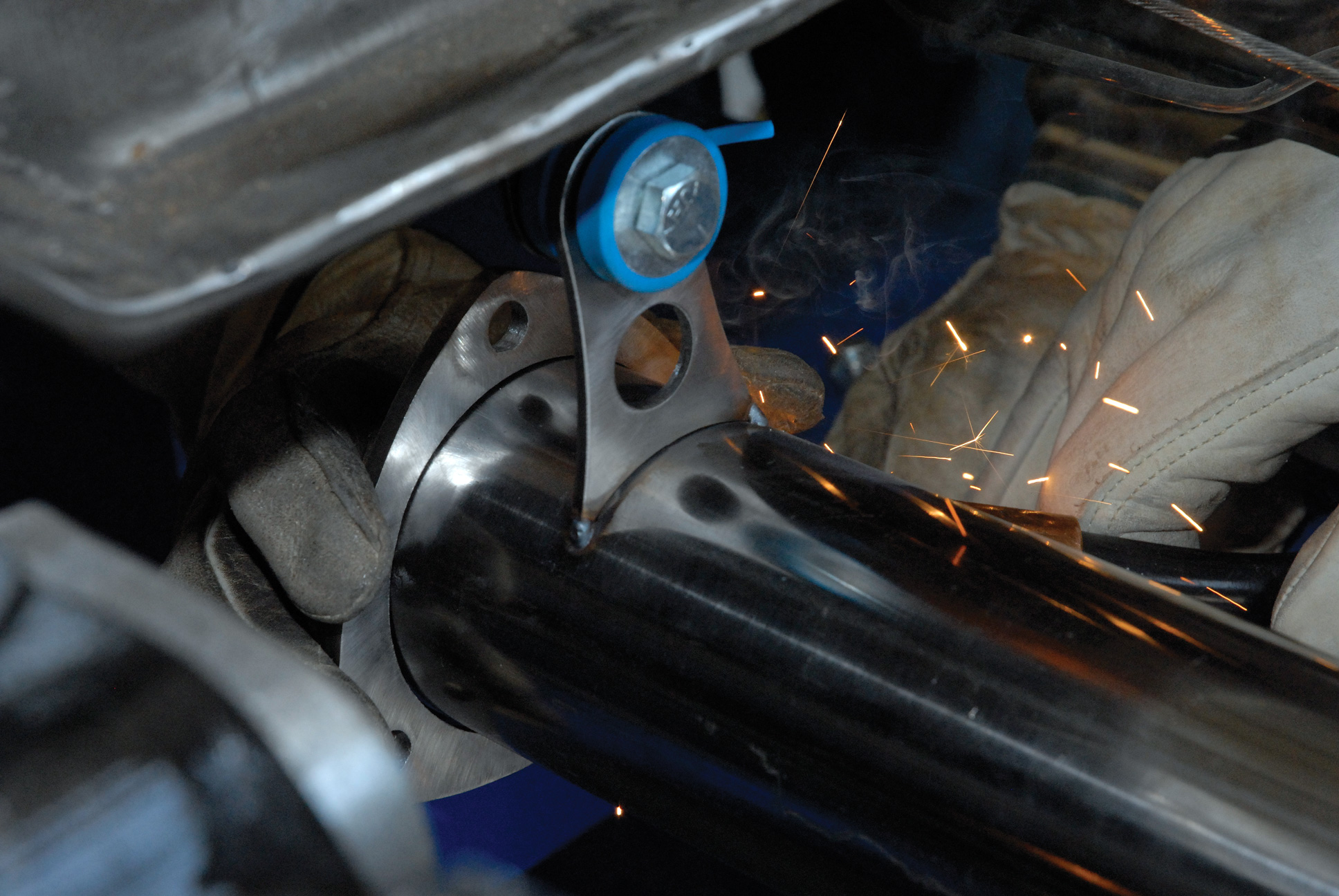
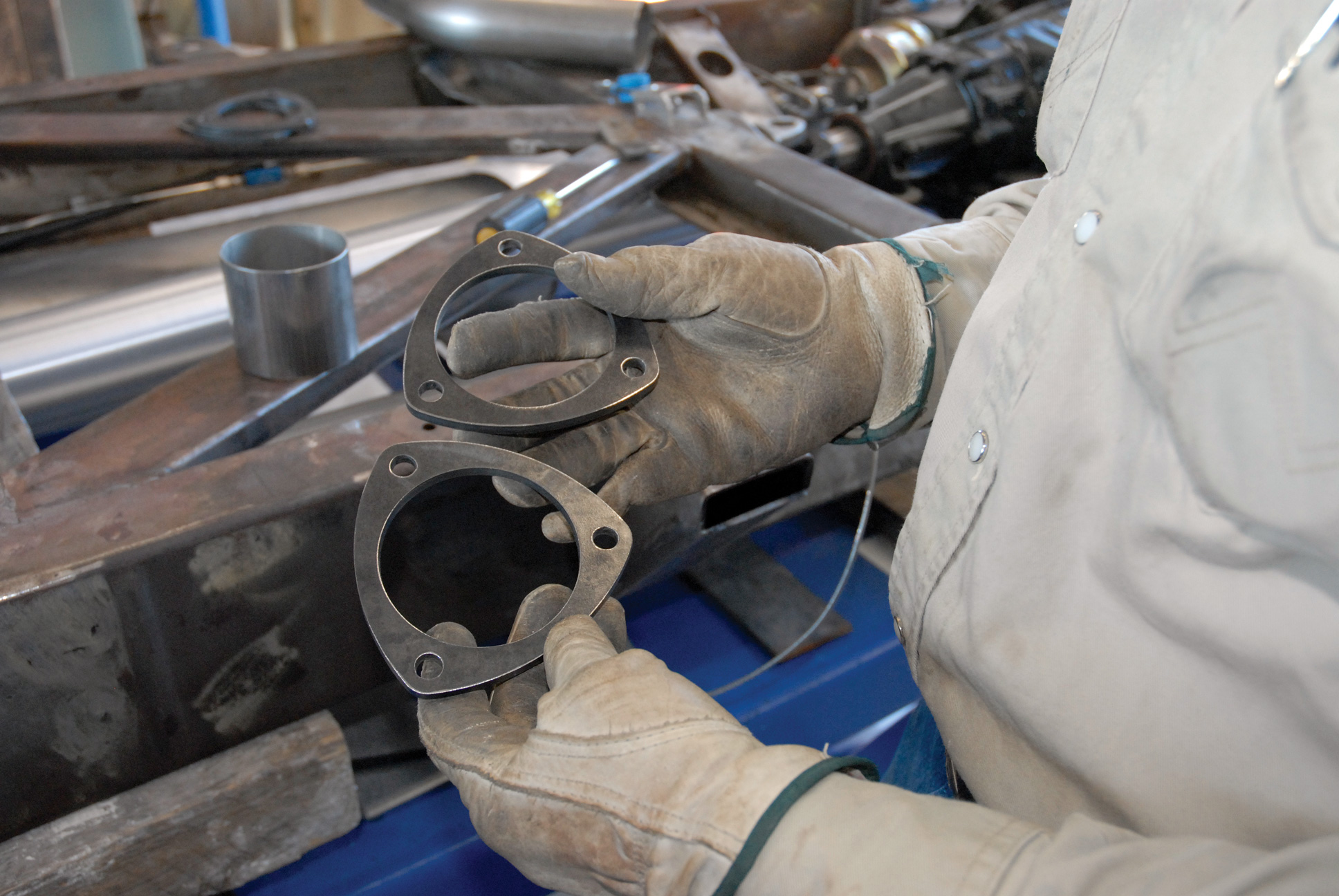
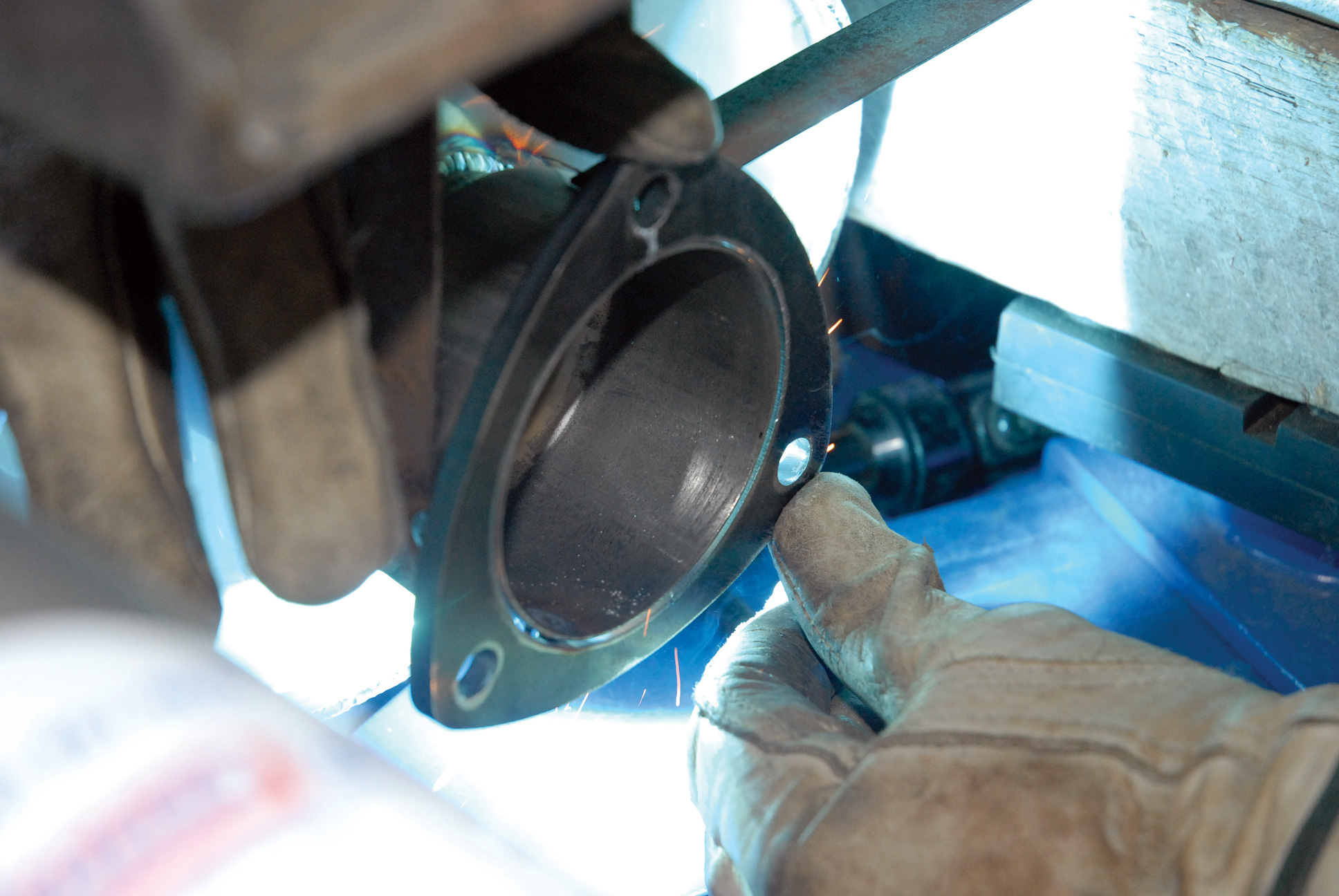
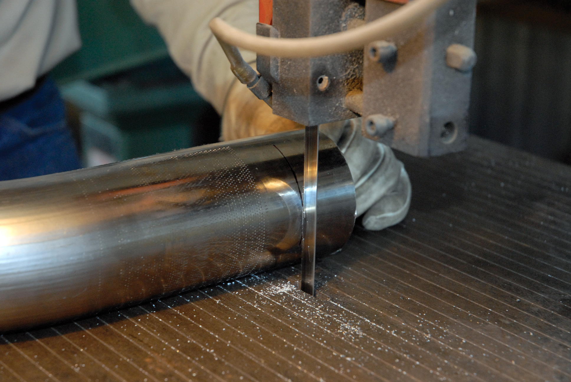
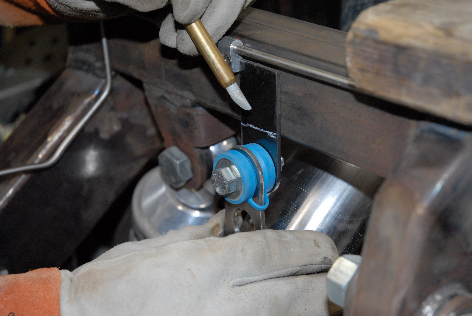
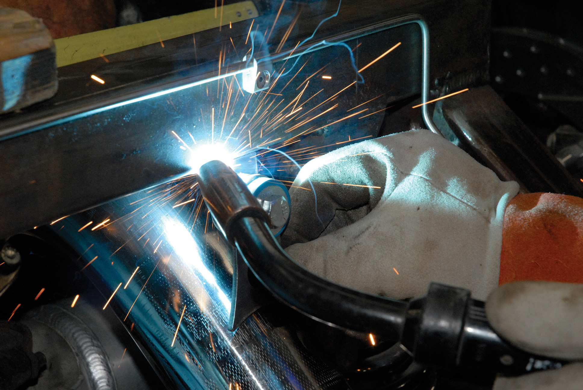
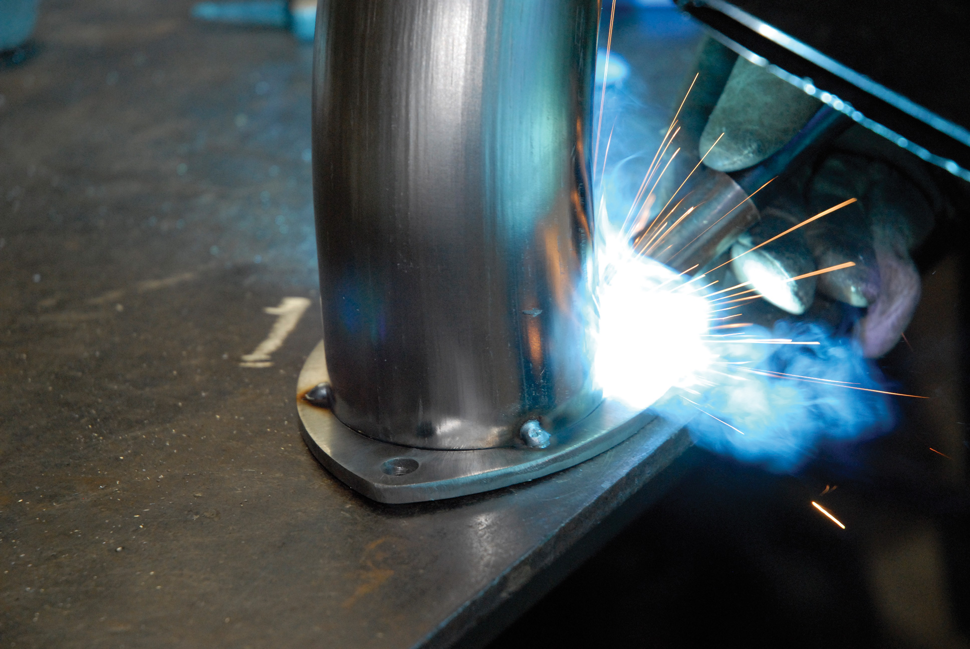
Once it had been tack-welded together as a unit, the team then located the exhaust hanger mounting locations. Since this was a custom installation, the guys determined that the exhaust hanger brackets had to be modified from their original shape, along with coming up with some special mounting tabs made from 1-1/2-inch steel strap. With that done, the next step was breaking up the exhaust system into four manageable sections, or subassemblies, for ease in handling. Rather than use the provided band clamps, Dennis and Jerry fabricated a total of 16 3×3/8-inch stainless steel exhaust flanges using a Plasma Cam CNC machine. These flanges are located at the collector at both the entry and exit sides of the mufflers, and on the downside of the exhaust riser below the rear crossmember to the inside of the Aldan Eagle coilover rear shocks.
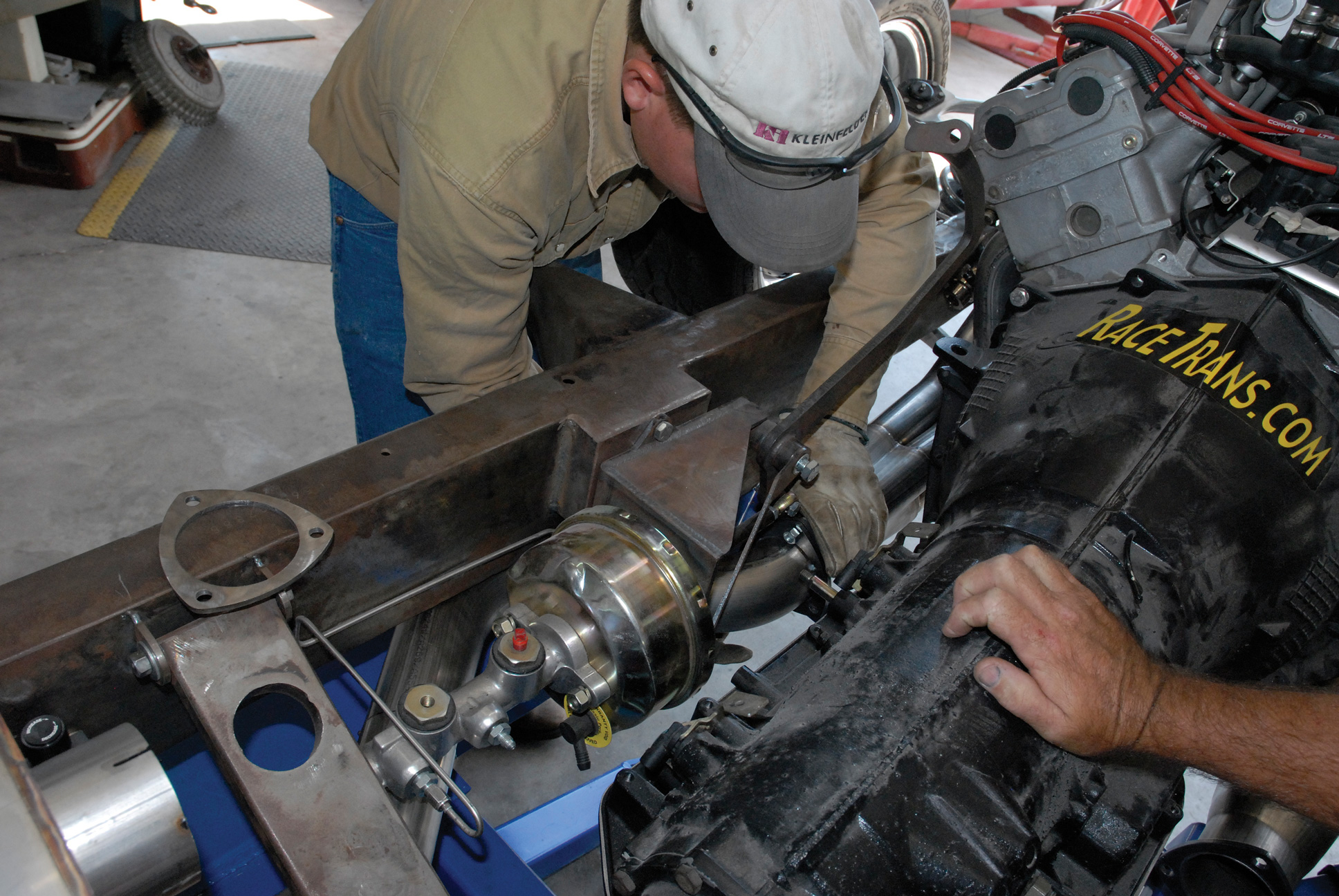
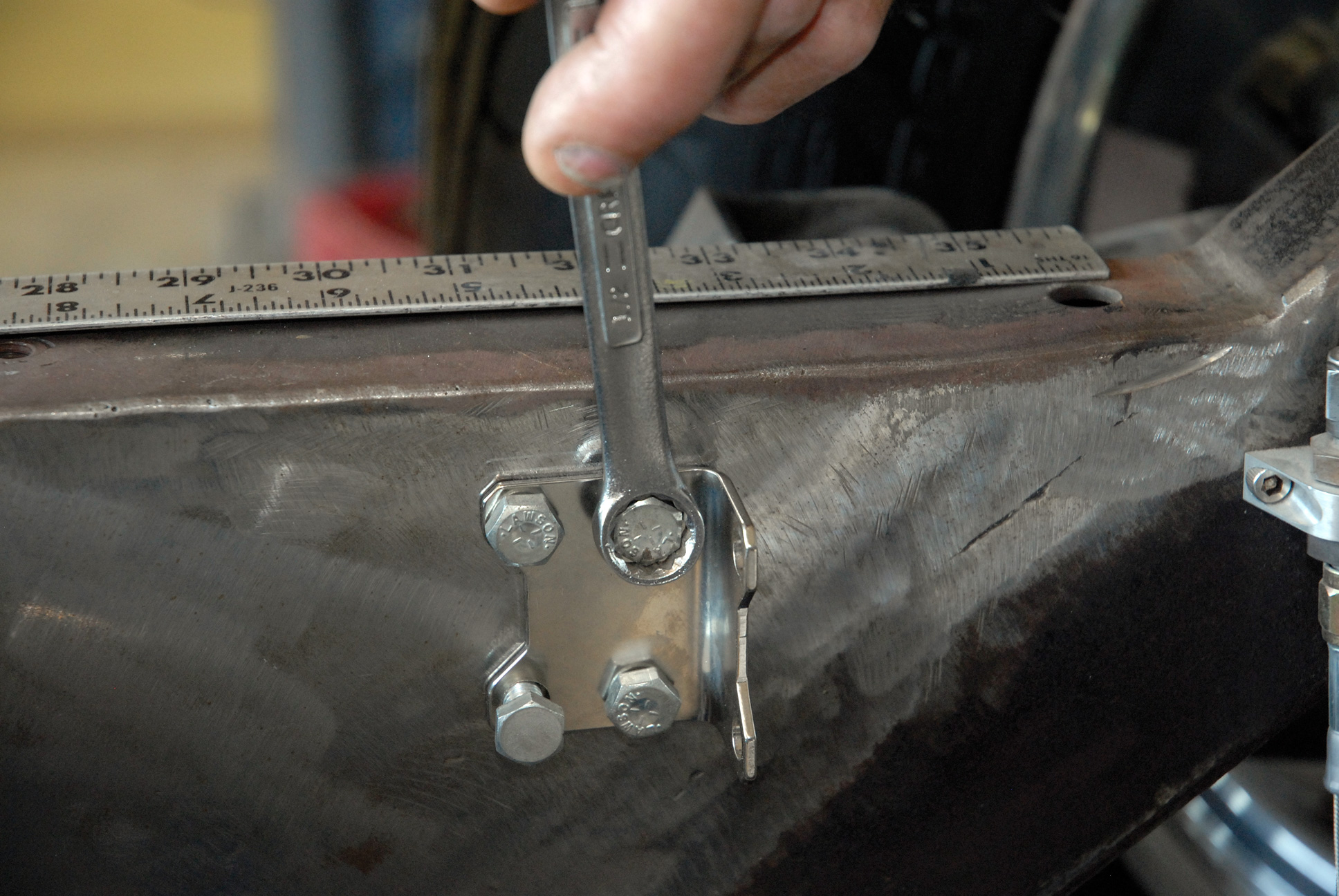
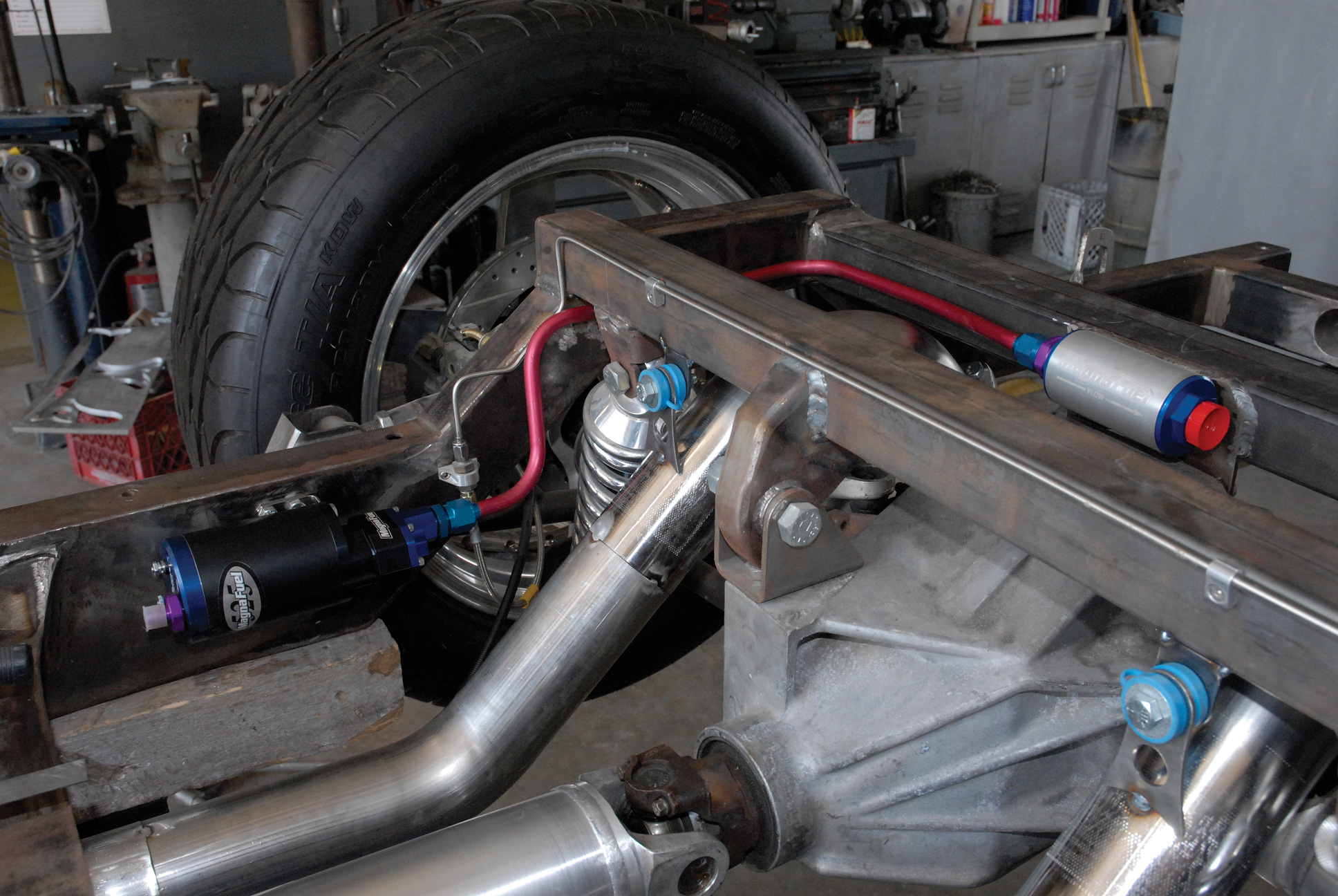
With the exhaust system in place, the next step was locating and plumbing the fuel system. First Darrell determined a suitable location for the MagnaFuel 74-micron medium filter at the center of the rear bulkhead directly above the Corvette gear case. This filter features a custom-bent, 1/2-inch aluminum fuel outlet hard line, which will run from the bottom of the tank up through the filter and then snake down around the passenger’s-side coilover shock, where it will join with the MagnaFuel ProTuner 525 electronic fuel pump. From there fuel will exit through a 3/8-inch aluminum hard line running through MagnaFuel’s 74-micron small inline filter, located near the aft side of the rear transmission crossmember. From there the line will continue along the top framerail to the MagnaFuel standard bypass regulator, which will be mounted to the chassis directly across from the power brake booster. Finally, both inlet and outlet fuel lines will be routed to the yet-to-be machined Cimtex fuel block on our Corvette ZR1 engine via a pair of braided stainless steel fuel lines.
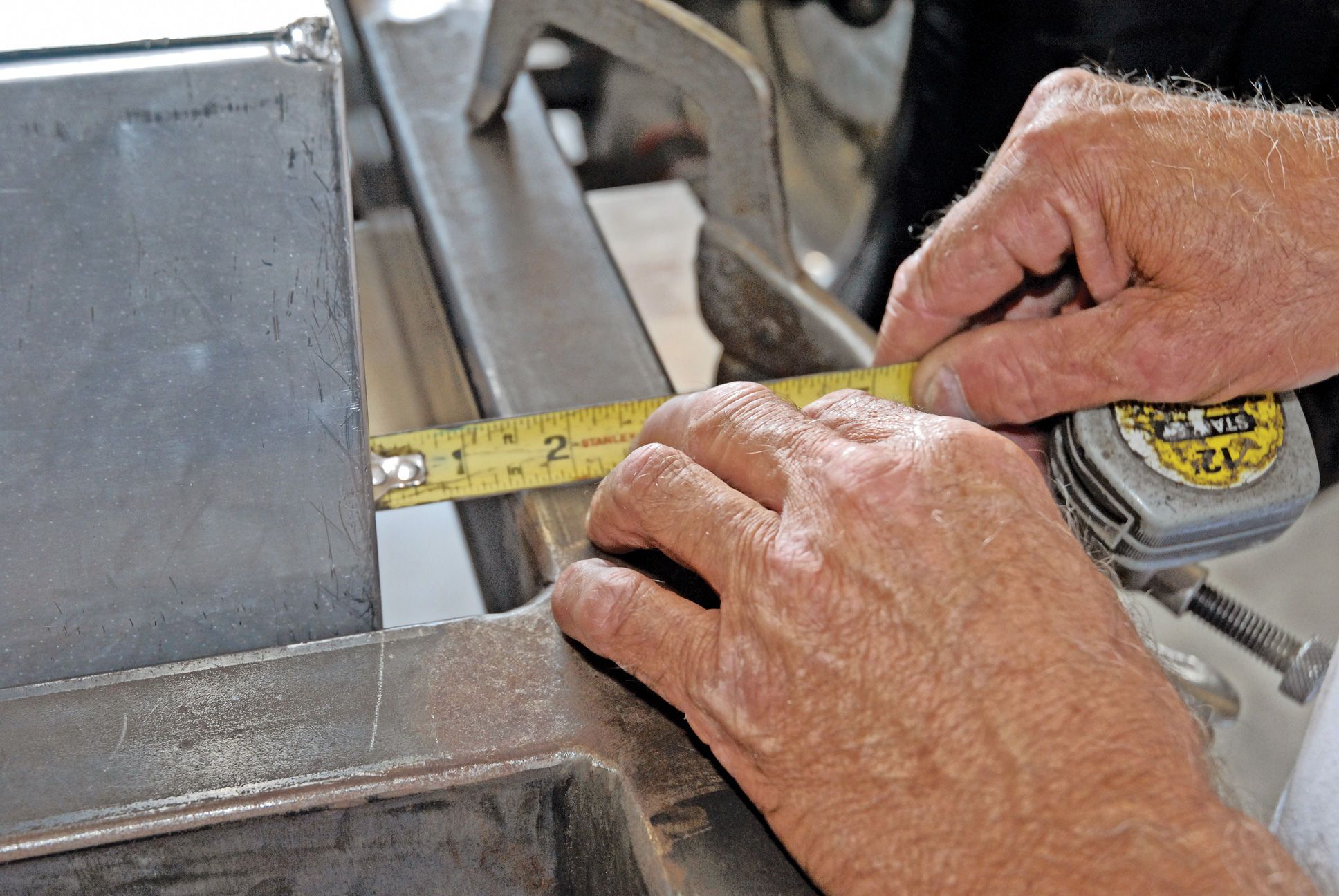
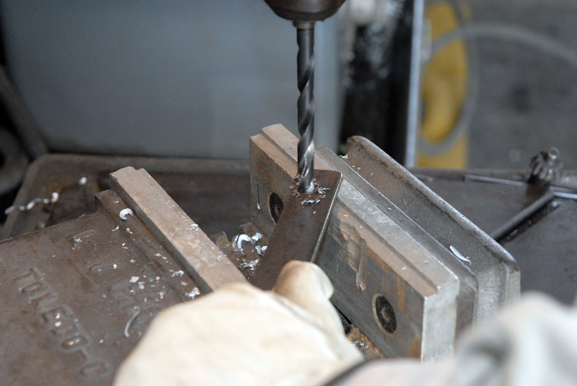
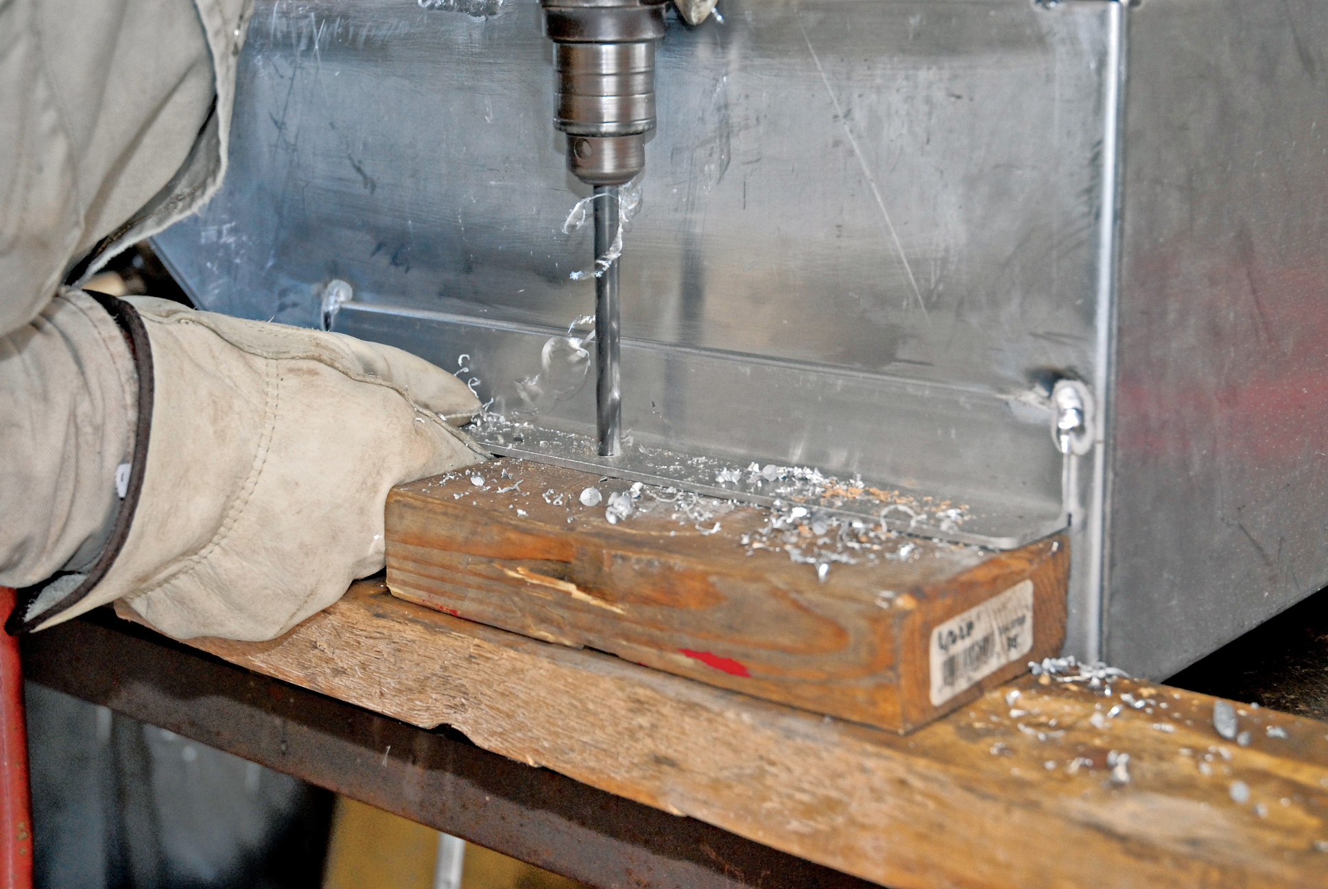
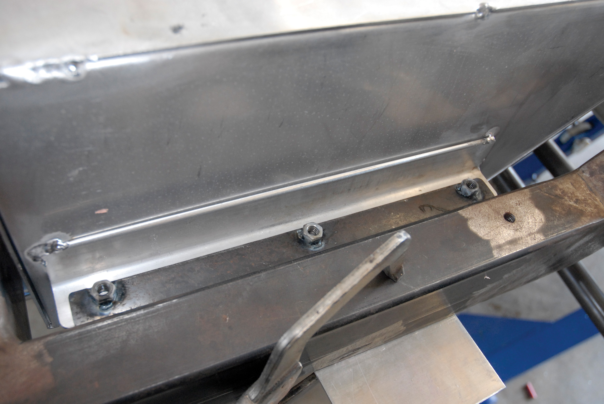
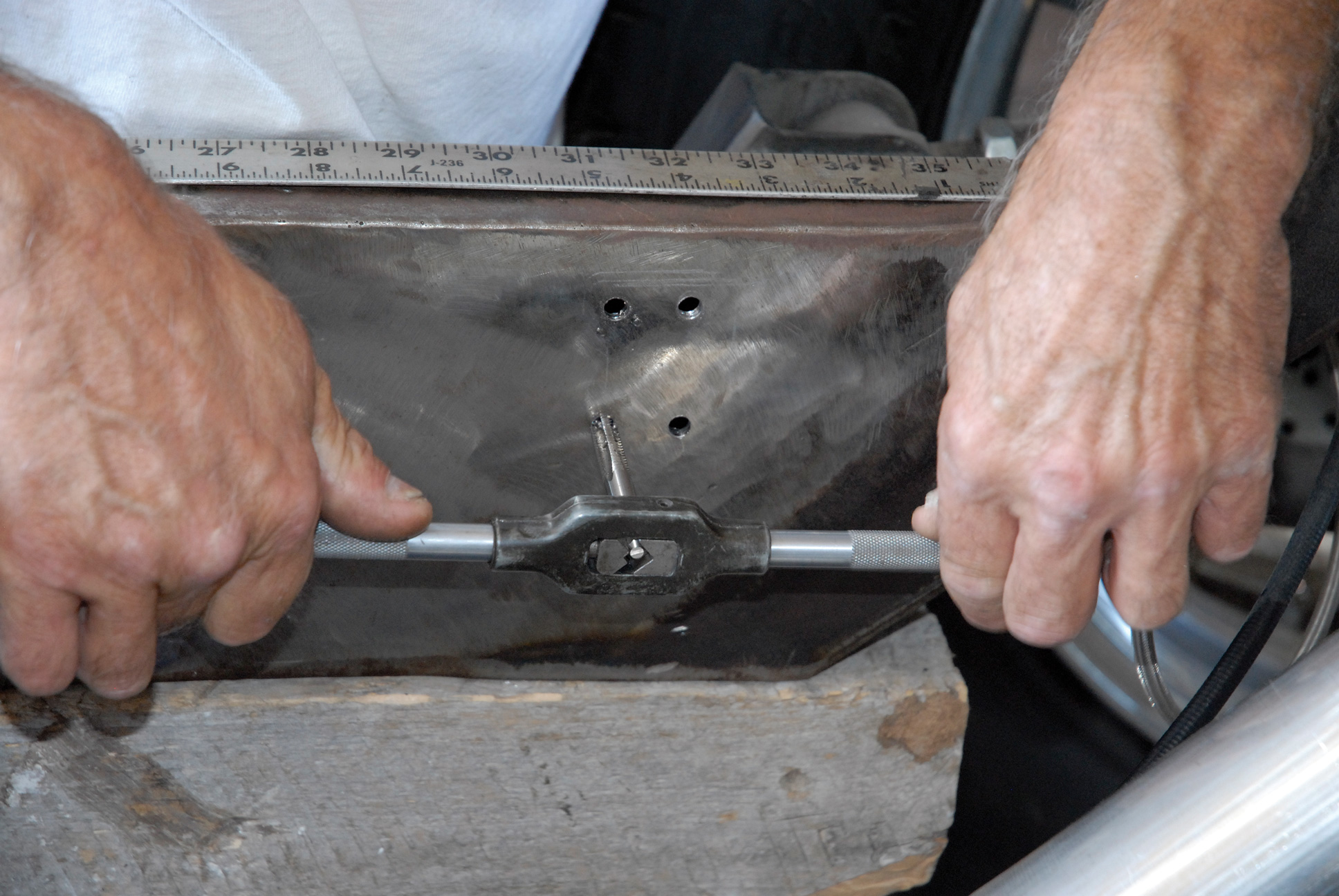
Next we mounted our gas tank to the chassis. This was accomplished by fabricating two pieces of 1-1/4-inch aluminum channel measuring 12 inches in length. Once the tank was positioned, these runners were tack welded to the sides of the tank. Then a pair of 1-foot by 1-inch flat steel straps was fabricated, and a series of three 3/8-inch holes was drilled. These straps were then aligned with the gas tank mounting brackets. Six 3/8-inch steel nuts were tack welded onto the brackets.
Obviously, a lot of work went into both the exhaust and the fuel systems, but the effort was well worth it. All told, the exhaust system measured 10.83 feet from collector to tailpipe on each side. In the process, a total of 8.83 feet of 3-inch stainless steel tubing was used per side to fabricate our system.
Note: Please understand that some components may be present in some of the pictures shown, yet be missing in others. This is due to the fact that we had two fabrication teams simultaneously working on the exhaust and fuel systems in order to meet our editorial deadline, so some shots had to be photographed out of sequence. This doesn’t affect the outcome, but it will save you eagle-eye techies from having to write us.
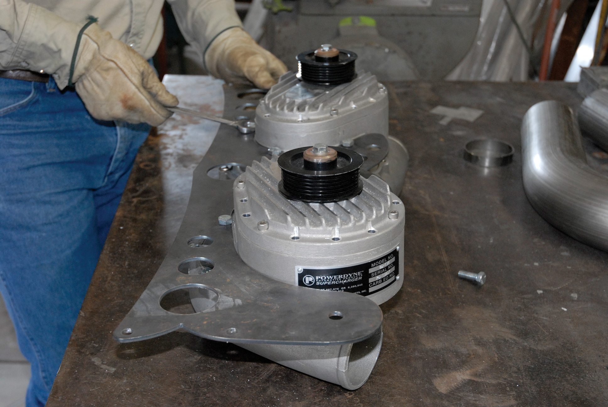
In the next installment, Cimtex will prototype the twin Powerdyne BD11-A Silent Drive superchargers, along with fabricating the overall induction systems package, which includes some pretty trick CNC laser-cut mounting brackets. Finally, we’ll cover the installation of our new Be Cool four-core aluminum radiator and dual electric fan assembly. Stay tuned!


