INSTALLING A CUSTOM-MADE TOTAL COST INVOLVED IFS ON A ʼ27 CHRYSLER
Tom Lawson was attending the Goodguys West Coast Nationals with his family and friends when a friend of his father-in-law, Bill, also a street rodder, walked up and started talking to everyone in the group. During the conversation, the fellow mentioned that he was selling a ʼ27 Chrysler phaeton. He had some pictures with him, and the car was very nice. He said that he had purchased the car with the intention of restoring it but had lost interest along the way because he preferred street rods. The car looked expensive, but when he told everyone that he was willing to sell it for $5000, it got their interest. Lawson was especially interested and looked at the pictures again. He thought about it and said that he would buy it. Sounds familiar, right?
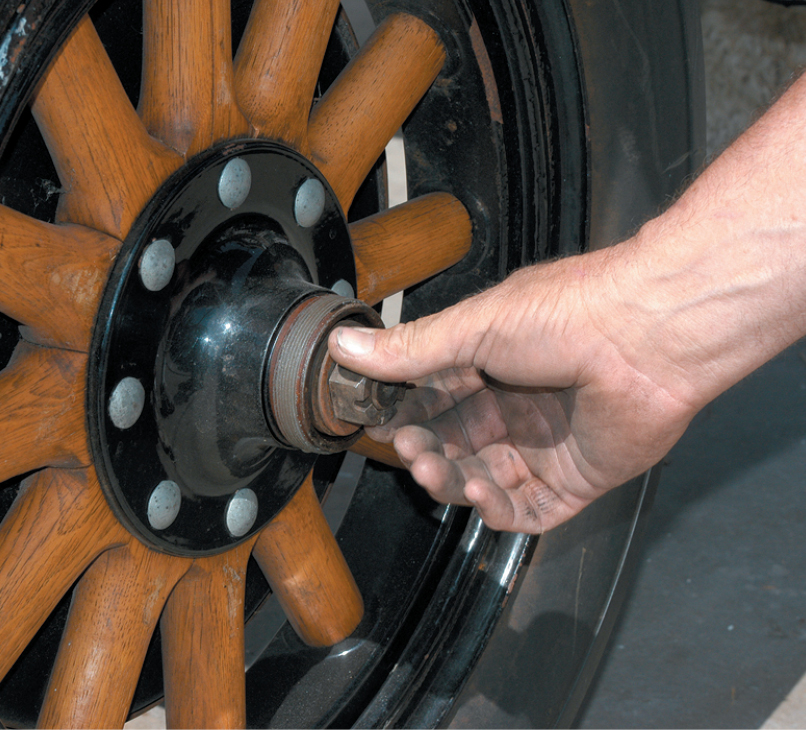
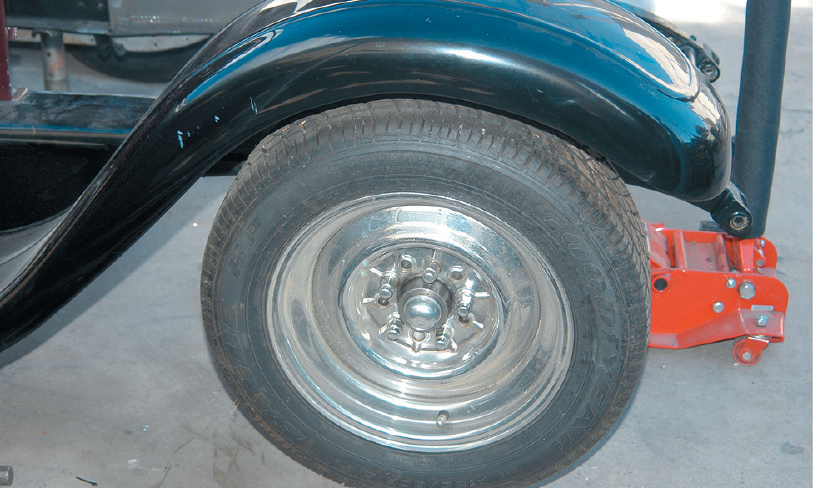
The first step was to disassemble the car. The spindle nut on each wheel was removed to access the suspension parts.
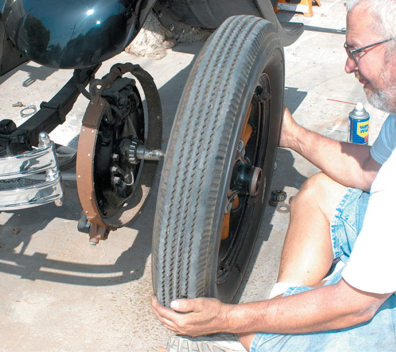
The old wood spoke wheel was removed. Note the brake lining that presses against the brake drum that’s connected to the wheel. This car actually had hydraulic brakes in 1927.
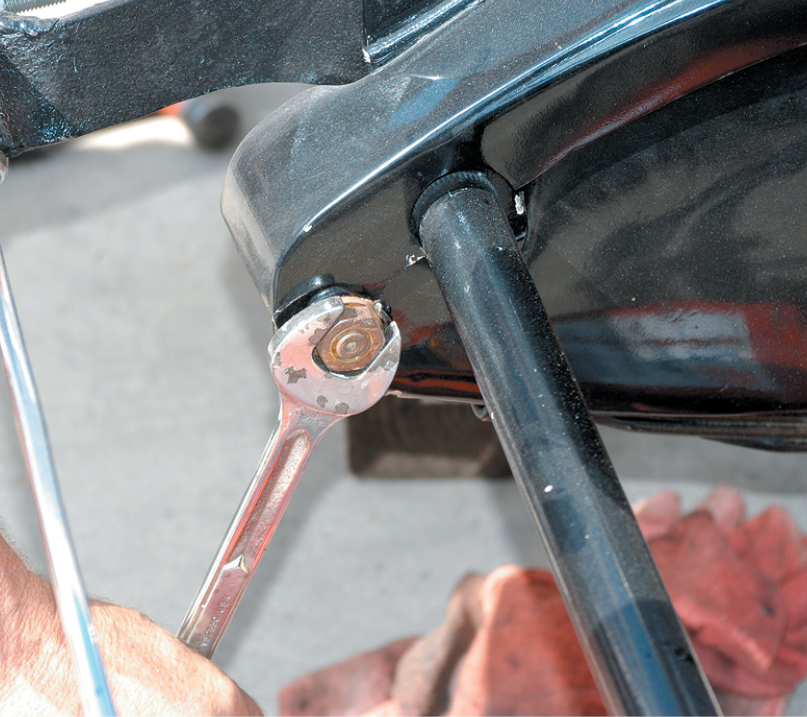
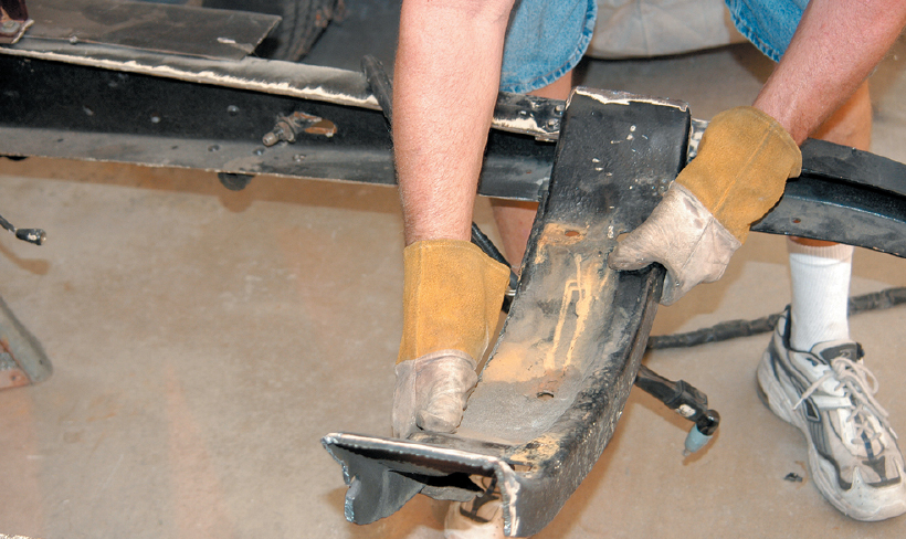
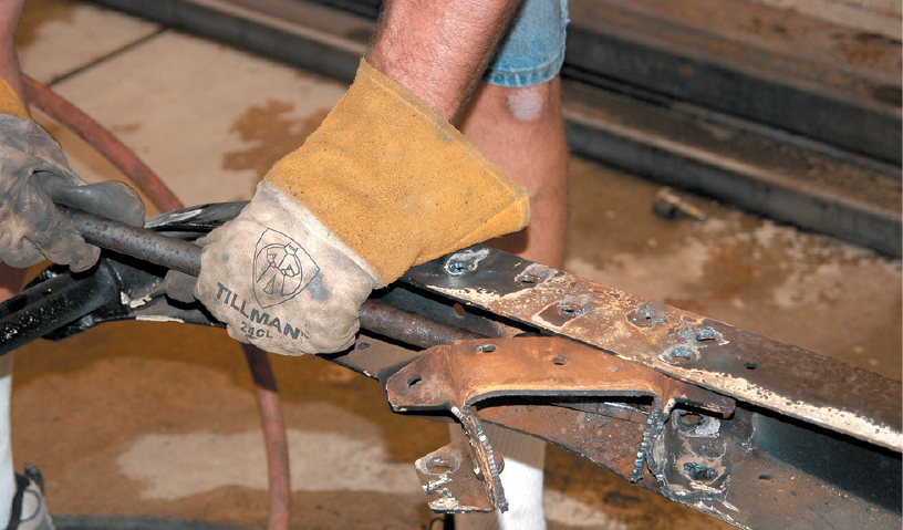
The front and rear spring bolts were disconnected to remove the front transverse leaf springs. The assembly was removed as a complete unit.
Tom Lawson was attending the Goodguys West Coast Nationals with his family and friends when a friend of his father-in-law, Bill, also a street rodder, walked up and started talking to everyone in the group. During the conversation, the fellow mentioned that he was selling a ʼ27 Chrysler phaeton. He had some pictures with him, and the car was very nice. He said that he had purchased the car with the intention of restoring it but had lost interest along the way because he preferred street rods. The car looked expensive, but when he told everyone that he was willing to sell it for $5000, it got their interest. Lawson was especially interested and looked at the pictures again. He thought about it and said that he would buy it. Sounds familiar, right?
Lawson brought the car home and planned to finish the restoration, but it was soon put on the back burner as other projects became more important. Recently, he was wondering what to do with the Chrysler, because a restored phaeton wasnʼt getting him excited. One of the problems he faced was that a perfectly restored car was only worth about $12,000, and his was far from finished. He thought about selling the car, but then a friend said, “Why donʼt you turn it into a really wild street rod? Install an IFS front suspension and a Jag rear, and stuff a big Hemi into it. Do the car in a nostalgic style and it would really attract a lot of attention at rod runs. With the IFS and IRS, the old Chrysler would ride like a brand-new Cadillac—maybe even better.”
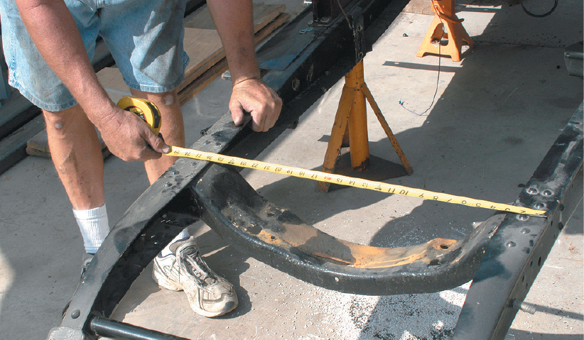
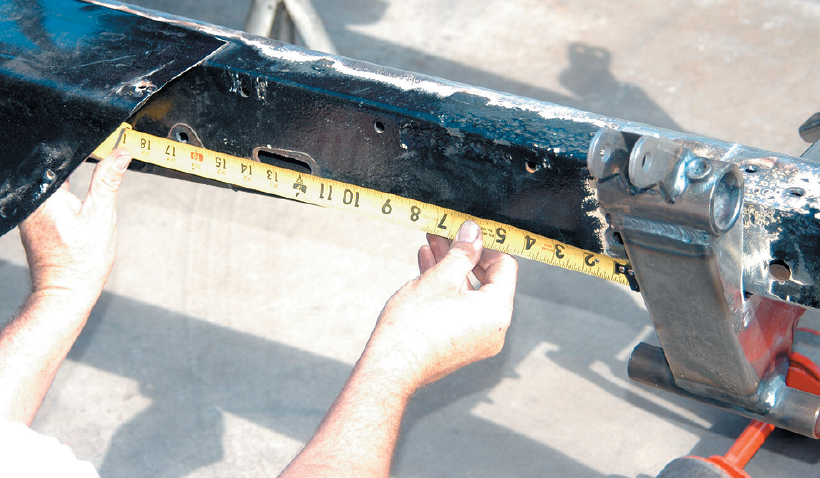
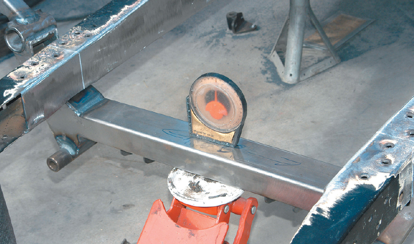
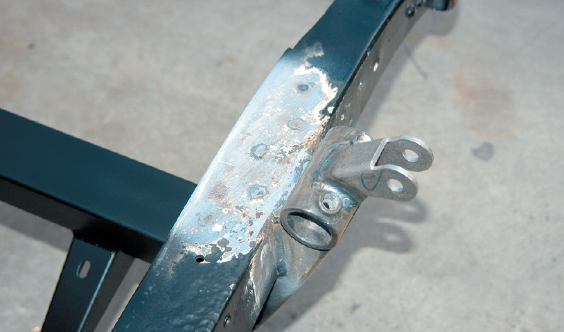
The frame width was measured, and it was very close to the width of a ’33-’34 Ford frame. Note how beefy the Chrysler chassis is, and it will be even stronger after it is boxed.
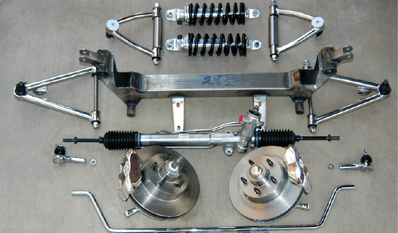
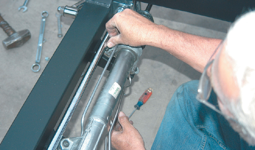
The Chrysler will be equipped with a custom-made Total Cost Involved Engineering independent front suspension system. The kit features the custom-made crossmember, upper and lower chrome-plated A-arms, spindles and brakes, a sway bar and coilover shocks. The kit also comes with all necessary hardware. This kit was ordered with a power rack-and-pinion steering system that will make the car a pleasure to drive.
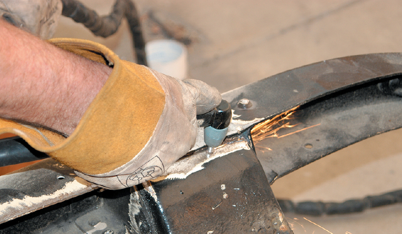
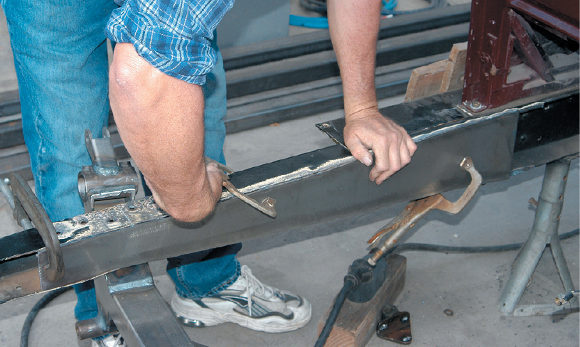
The front crossmember was removed to make way for the new crossmember. The frame and the stock crossmember were sanded to bare metal so the plasma cutter would work properly.
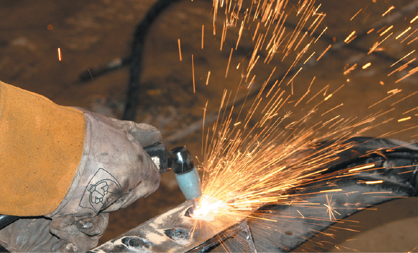
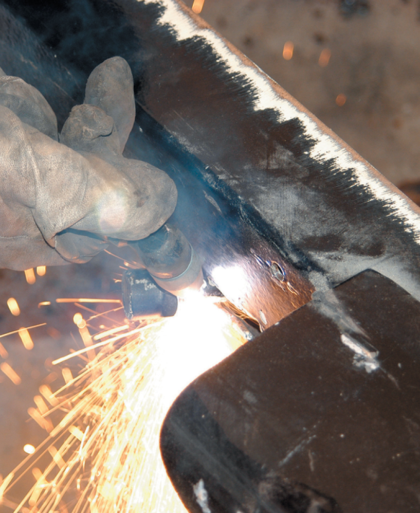
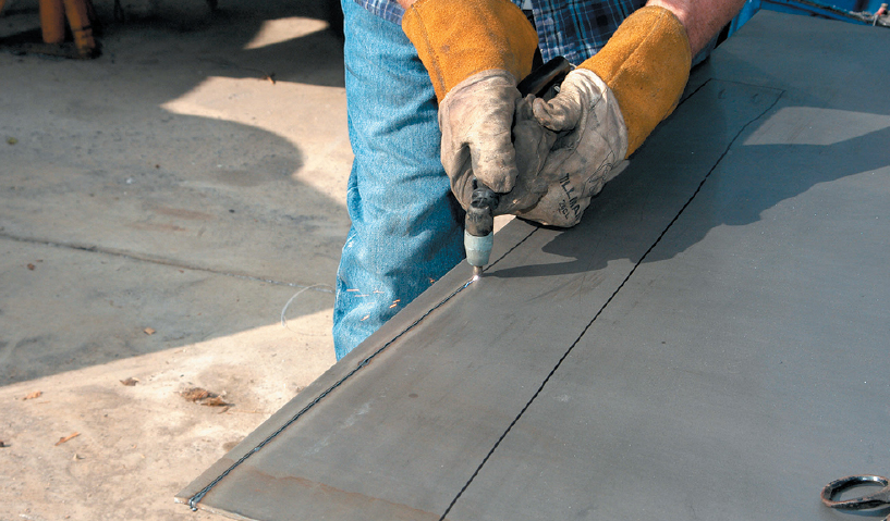
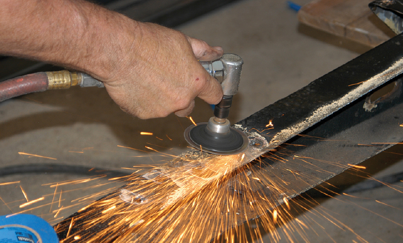
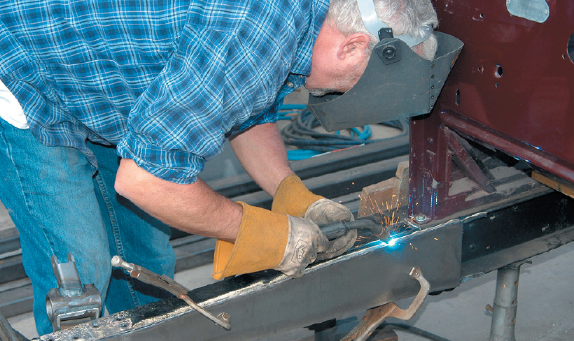
The crossmember is riveted to the frame, so the removal process was started by cutting the crossmember with the plasma cutter. The cut was made close to the frame, which will make it easier to remove the rest. The spreader bar at the front will keep the frame in place after the crossmember is removed.
After both sides were cut with the plasma cutter, the crossmember section was removed and discarded.
The rivet heads were cut off using the plasma cutter. The shank of the rivet was also cut through to make it easier to remove the remaining crossmember section.
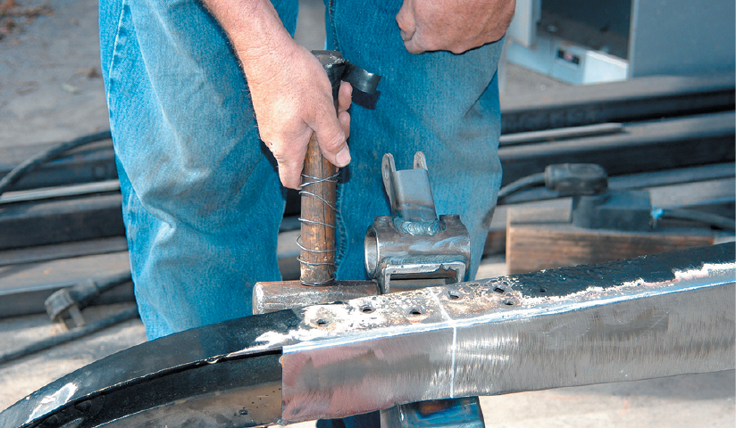
After the rivets were cut out, a hammer was used to loosen the remainder of the crossmember.
The remaining section of the crossmember was very secure in the frame, so it took several whacks of a sledgehammer to remove it.
The other side also needed plenty of persuasion. After loosening the remaining crossmember section with the hammer, it was finally removed with leverage from a pickle fork (ball-joint tool).
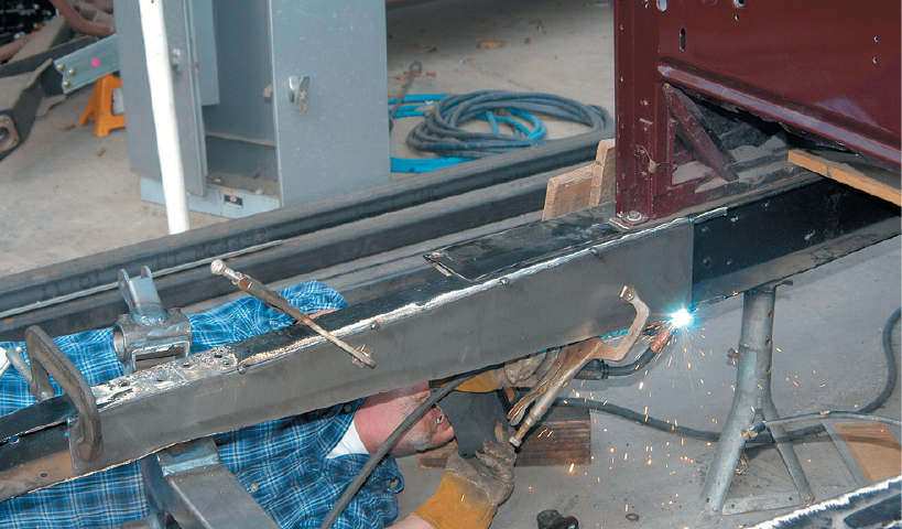
The steel brake line fitting was still running through the frame, so it was removed with the plasma cutter.
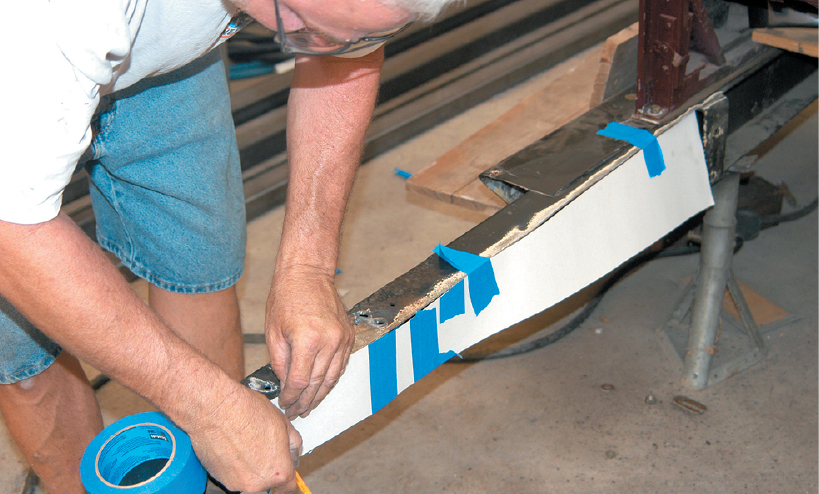
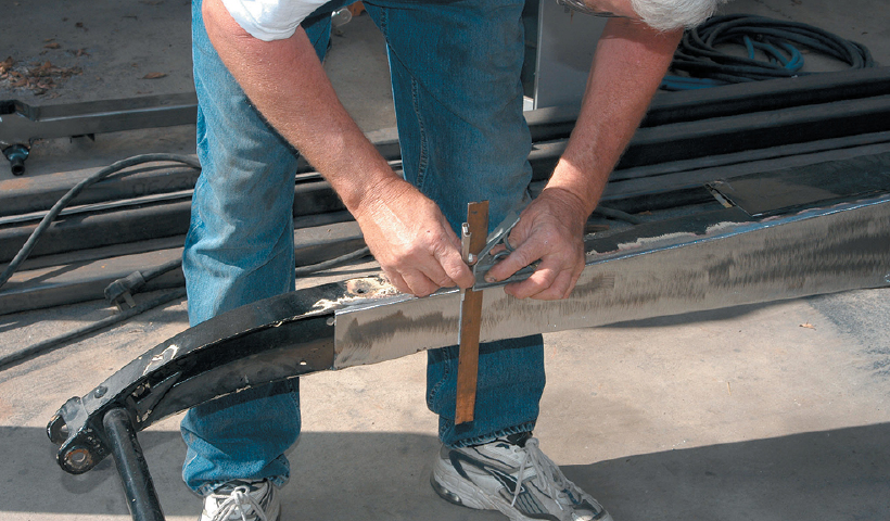
The frame had to be boxed prior to installing the TCI crossmember, so a pattern was made out of cardboard. It was held against the frame and the perimeter of the frame was marked with a felt pen.
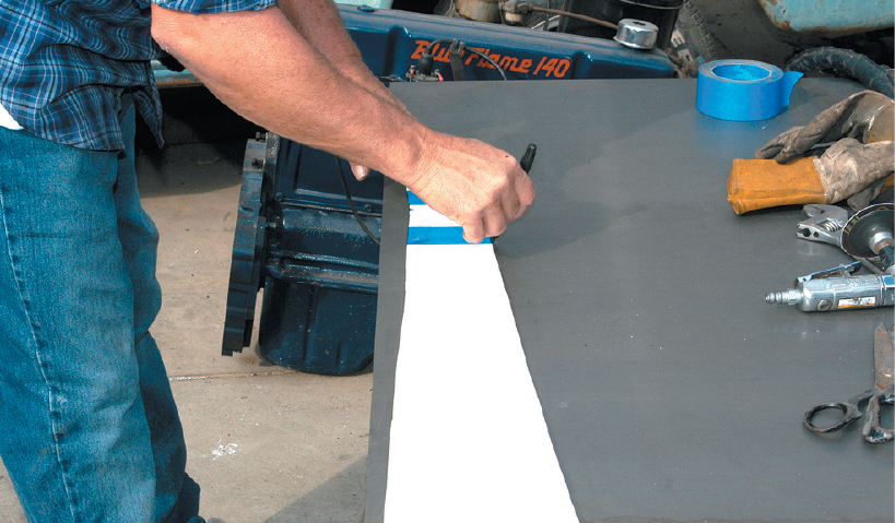
The cardboard was cut on the line and then placed on sheet steel. Using a black felt pen, the pattern shape was transferred to a sheet of 3/16-inch-thick steel plate.
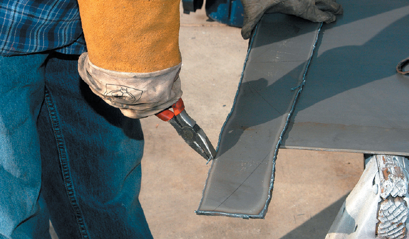
The boxing plate was cut with the plasma cutter. With a steady hand, it will turn out fine. If you are not this steady, a guide can be made with a piece of steel L-angle.
The cut was straight, but there was some leftover slag. The slag was removed before any other work was done.
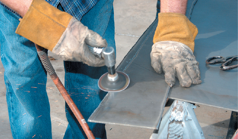
Removing the slag made it easier to grind the boxing plate. First the top was cleaned off to make it easier to weld.
The edge was also ground to get it perfectly flat. The plasma cutter works great, so only a small amount of grinding was needed.
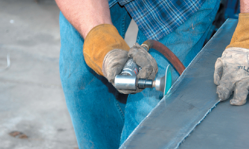
The frame was painted black, so the edge had to be sanded to bare metal on the top and bottom.
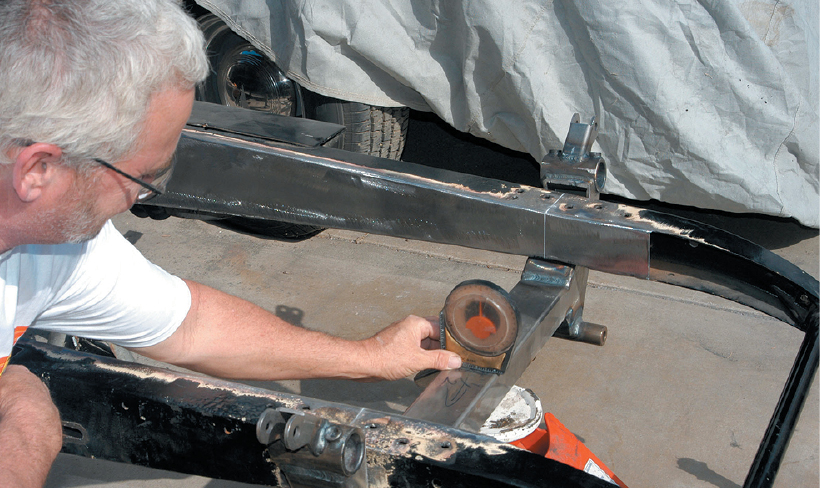
Before the original front suspension was removed, the axle centerline was located and properly marked. At this point, the mark was used to find the centerline for the TCI crossmember.
The front crossmember was installed in the frame, and it turned out to be a tight fit. Some minor trimming was necessary.
Using the plasma cutter, a small sliver of metal was removed from the crossmember.
After the crossmember was trimmed, it was reinstalled under the frame. It was still a tight fit, but it did line up with the centerline. Now the boxing plate can be installed.
The boxing plate was clamped to the frame in the center and at both ends to make sure it was a tight fit.
The top side of the boxing plate was tack welded in several locations.
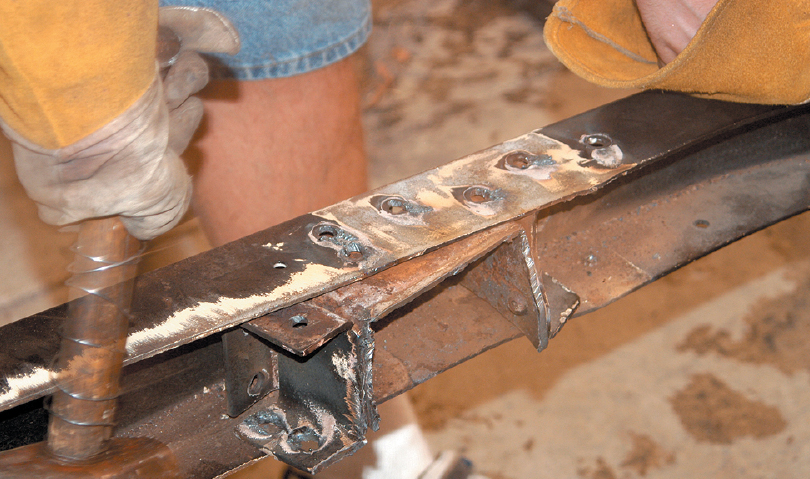
After the top was secure, the bottom side of the boxing plate was tack welded to the frame. That was followed by finish welding the frame, moving from one side to the other to spread out the heat.
The centerline was transferred to the boxing plate before the crossmember was installed. It will make it easier to locate the crossmember.
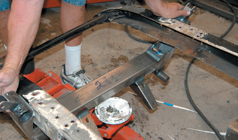
The crossmember was suspended on the jack, and then it was lined up under the frame. Since it was a tight fit, small adjustments were made by tapping the crossmember with a hammer.
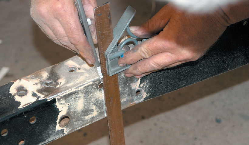
To be certain that the crossmember is in the frame straight, measure and re-measure.
Measurements were made side to side to make sure the crossmember was centered perfectly. This is critical on this frame because there are no instructions to follow.
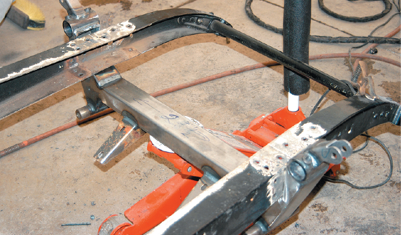
The angle of the crossmember was also checked with an angle finder. Remember that the chassis will be sitting on a rake, so you have to keep that in mind when the measurements are made.
The side-to-side angle was also checked to make sure that the crossmember was accurately located. The frame was level and so was the crossmember.
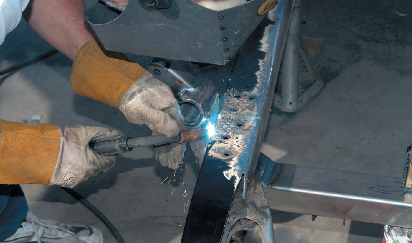
Satisfied that the crossmember was installed in the frame correctly, it was then tack welded to the frame.
We then moved to the other side and tack welded the crossmember to the frame. Now both sides were secured to the frame.
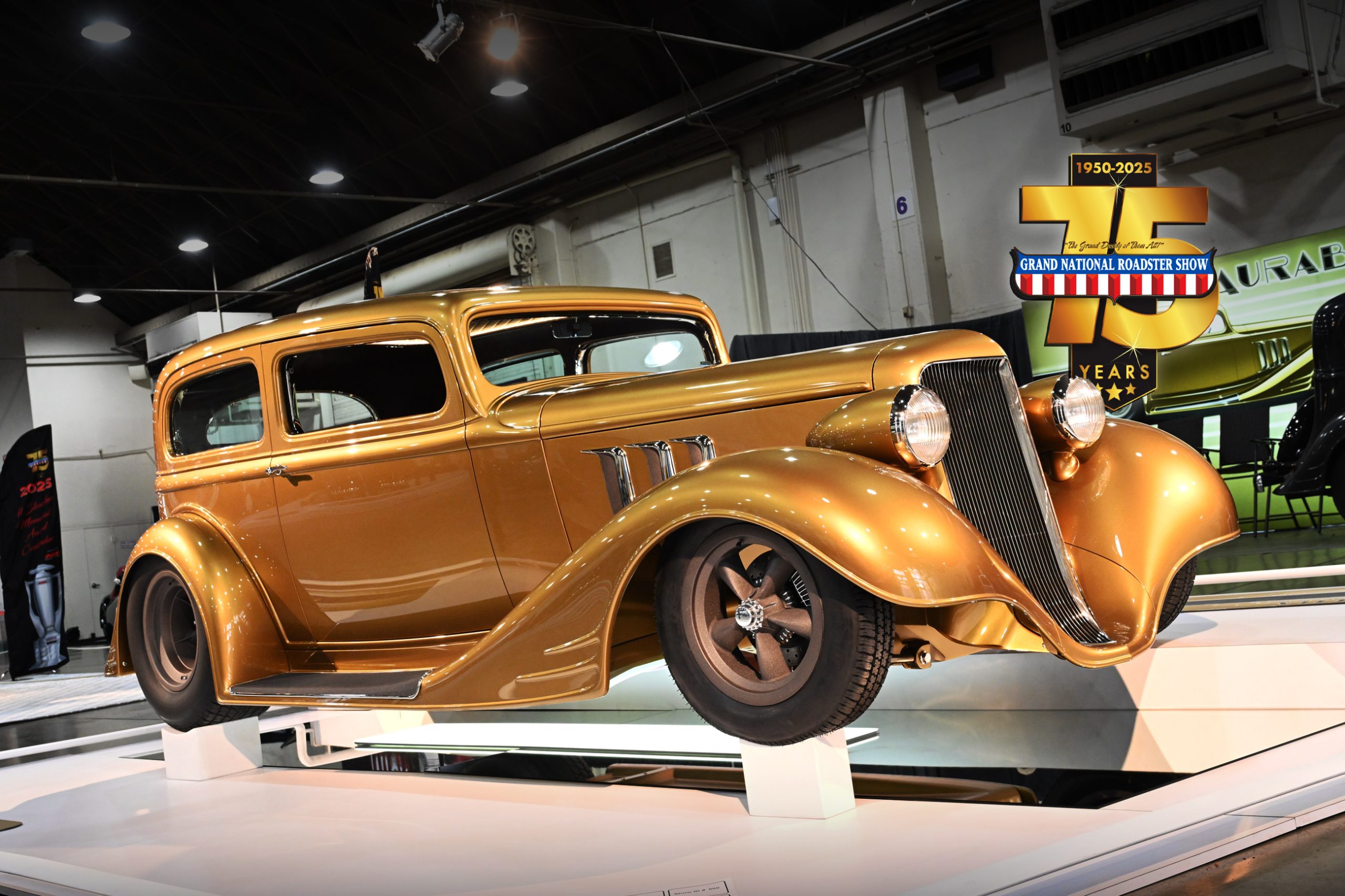
By this time, Lawson started picturing the Chrysler in his mind as a street rod, and he liked what he was visualizing. The old Chrysler didnʼt have a lot of value as a restored car, but as a street rod the value of the old car would be much better. He wanted to buy a street rod ʼ32 Ford roadster, so this street rod phaeton could take its place. After all, Deuce highboys are everywhere, but this Chrysler would be a real conversation piece.
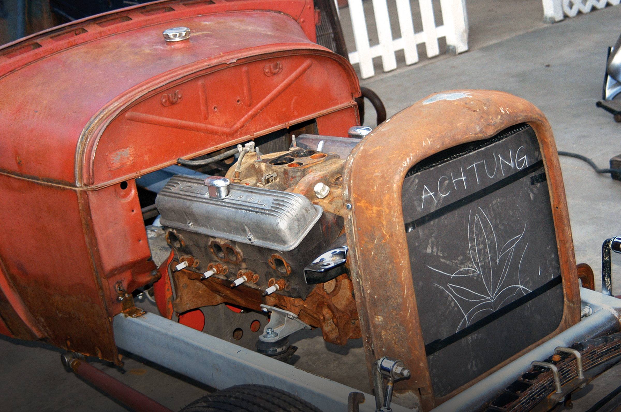
The Chrysler was delivered to Dream Cars for the installation of a Total Cost Involved Engineering (TCI) front suspension. Lawson is still deciding whether he wants to install a Jag or a Heidtʼs IRS suspension, because after detailing and chrome plating the Jag, the cost will be a push. While he was at NHRAʼs California Hot Rod Reunion, he ran across a fellow who was selling early Hemi engines. The fellow had a nice healthy 392 for sale, so Lawson purchased it and was on his way to building that really wild street rod.
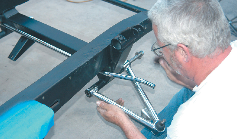
To make sure the crossmember was centered in the frame and the wheels and tires would look correct under the front fenders, the suspension parts were mounted for fit up. They appeared to be in the correct location.
Just to make sure everything was correct before the crossmember was finish welded to the frame, a tire and wheel combination was mounted and positioned in place. As you can see, the tire is right where it should be.
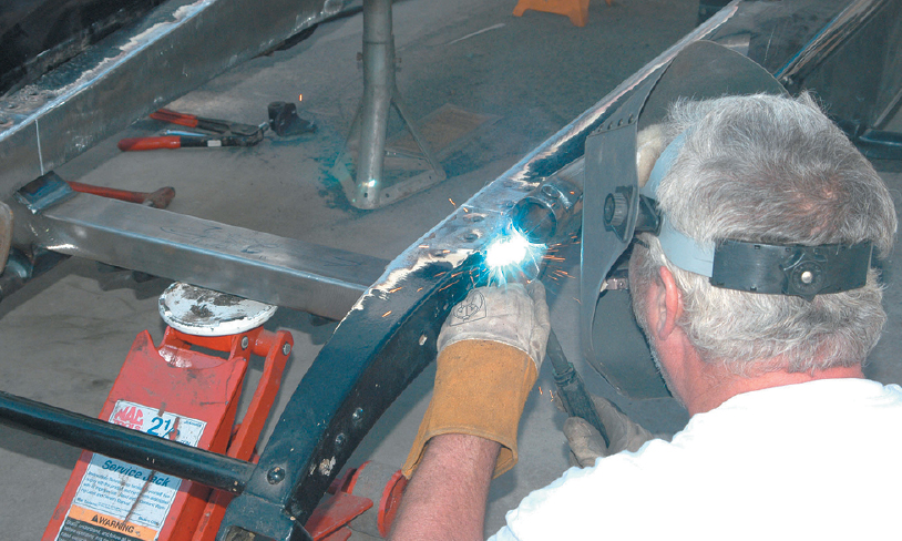
The suspension parts were removed and the crossmember was finish welded in the frame.
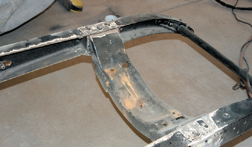
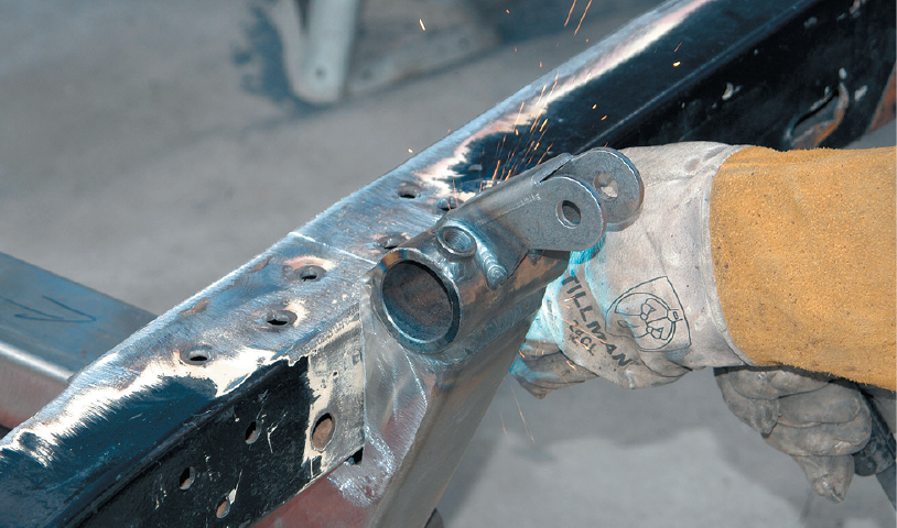
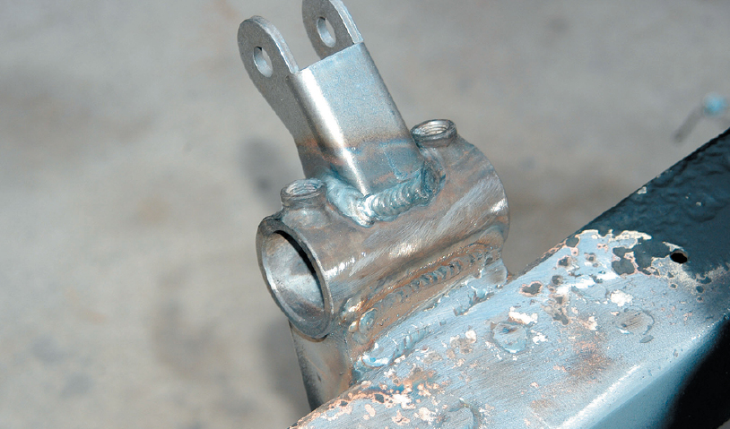
Here’s the crossmember after it was finish welded to the frame. It looks strong and secure.
The backside of the crossmember was open, so the opening was boxed. Since the fenders ride against the frame, we made sure there was fender clearance.
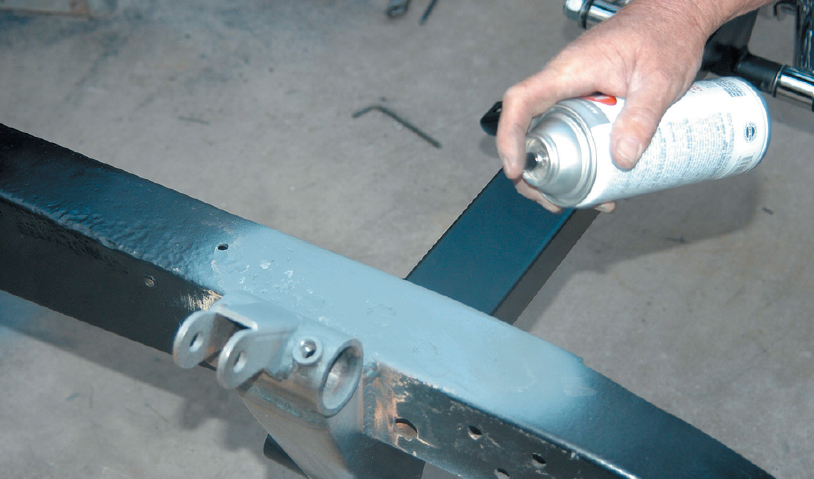
Before the suspension parts were installed, all of the bare metal areas of the chassis were painted with gray primer to keep them from rusting.
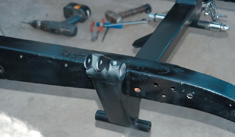
After the primer dried, the frame was painted with semigloss black paint. The frame will be detailed and painted with urethane later.
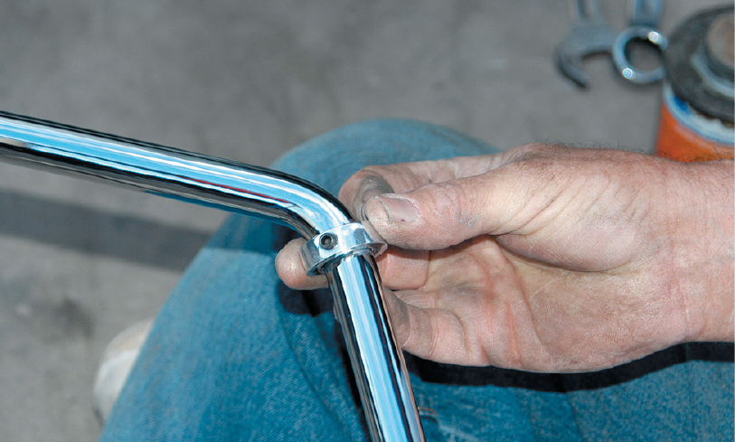
Now it was time for the installation of the suspension parts. The install was started with the sway bar and the billet retaining ring. After the sway bar is installed, this retainer will keep it centered.
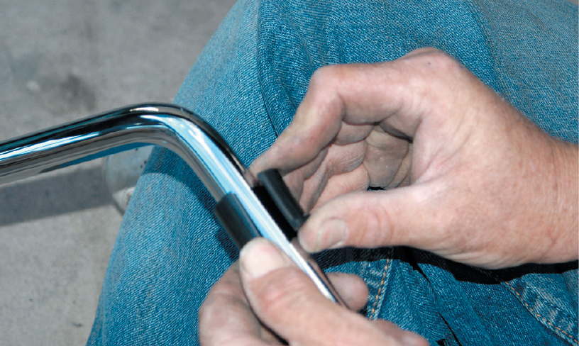
The nylon sway bar bushing was installed next. It looks like a solid bushing, but there is actually a split that opens up for installation.
The sway bar bracket was secured to the crossmember with two long Allen head screws. The nylon bushings are designed to slide into the bracket.
After the sway bar was centered, it was locked in place by screwing the Allen head bolt into the retaining ring. The retainer also secures the bushing into the bracket.
The lower A-arm was pushed into the lower crossmember boss. The long bolt runs all the way through, and then a Nylok nut was used to secure the arm. Large, flat washers were also used against the nylon bushings to keep them in place.
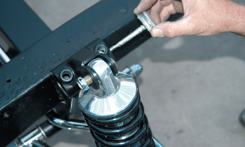
Next, the TCI coilover shocks were installed. One end of the shock bolts to the lower A-arm and the other bolts to the upper crossmember bracket. The upper bolt is short and is fastened with a Nylok nut. The lower bolt is longer and connects to the sway bar.
The upper boss for the A-arm is equipped with two holes for the Allen head locking studs. The threaded holes were coated with antiseize.
The eccentric was installed in the upper A-arm boss. The eccentric can be moved forward and backward for adjustment. The hole is not centrally located, so it will also move the A-arm outside or inside, depending upon what is needed. This eccentric is used to set the camber and caster. A long bolt connects the A-arm to the eccentric and the upper tower boss.
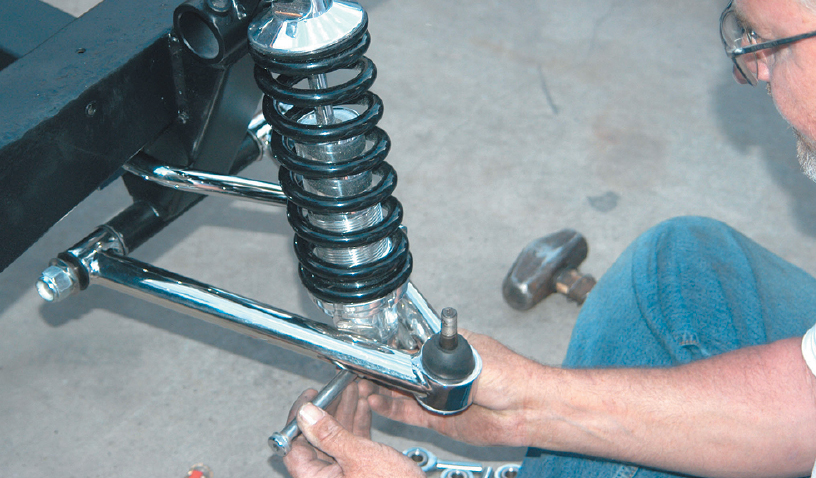
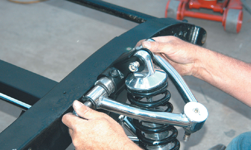
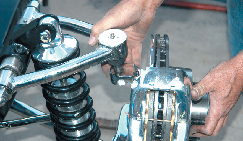
The upper A-arm was flipped out of the way, and the brake assembly was mounted to the lower A-arm. The TCI kit is delivered with an assembled brake and spindle to eliminate the problem of enthusiasts overtightening the spindle nut. This unit is equipped with a polished aluminum Wilwood caliper.
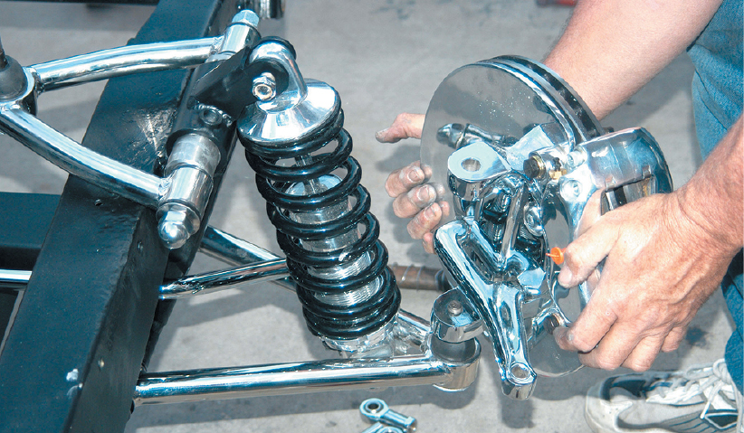
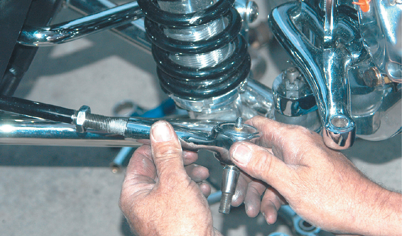
The brake assembly was slid onto a tapered ball joint and was secured with a castle nut.
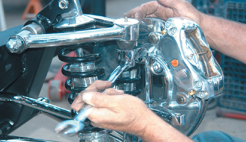
. After the brake assembly was attached to the lower A-arm, it was connected to the upper A-arm. This is also a tapered fitting that is fastened with a castle nut.
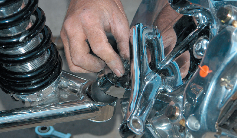
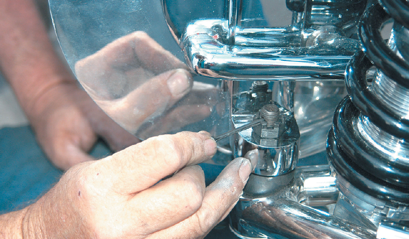
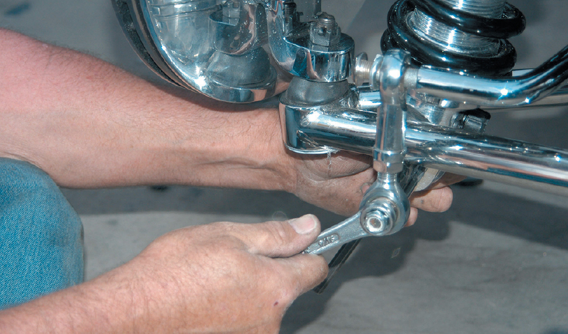
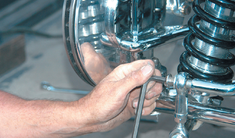
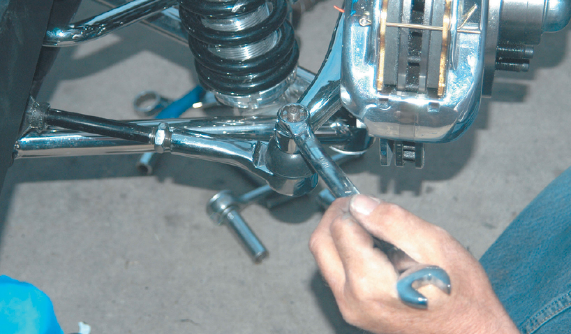
Using a 3/4-inch wrench, the castle nuts were secured. They should be very tight, and the top part of the castle nut should be aligned with the cotter keyhole in the shank.
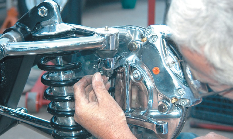
A cotter key was installed through the shank holding the upper bolt in place. This is extremely important, because it ensures that the bolt can’t loosen while the car is being driven.
The lower spindle nut was also secured with a 3/4-inch wrench.
The lower nut should also be secured with a cotter key.
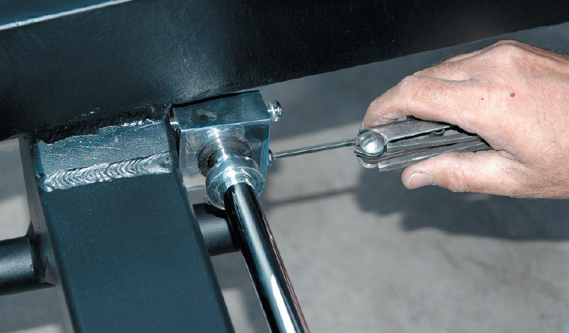
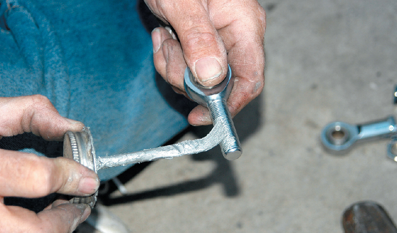
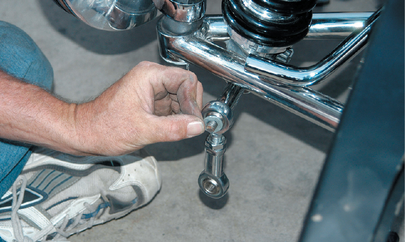
The sway bar connection was made from a male and a female Heim joint. The upper is being coated with antiseize lubricant to make adjustments easier. This keeps the threads from fusing together and helps eliminate the chance of cross threading.
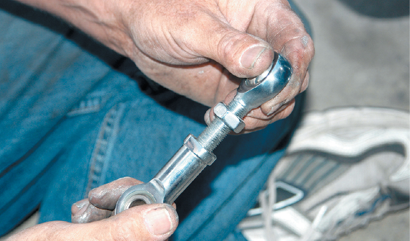
A jam nut was installed on the male Heim joint, and then the male and female were connected. After the proper adjustment was made, the nut was secured against the female Heim joint.
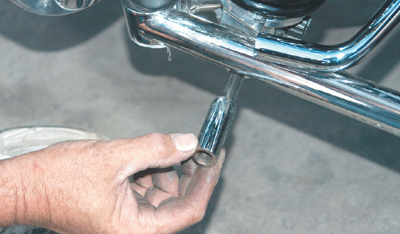
A chrome-plated spacer was installed on the long lower coilover shock bolt.
The Heim joint was connected to the lower shock bolt using a washer and a Nylok nut.
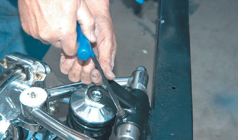
The upper portion of the Heim joint connecting rod was bolted to the sway bar using a large button-head Allen bolt.
Lock nuts were installed in the upper A-arm boss. These are used to hold the camber and caster settings after they are made.
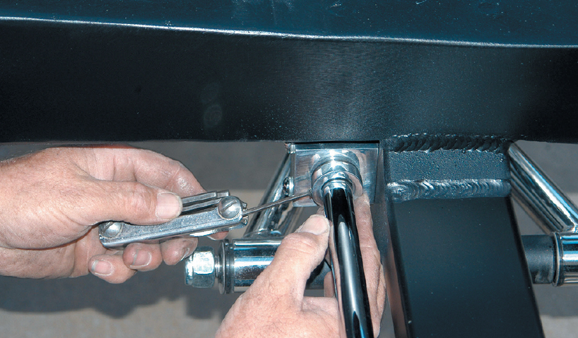
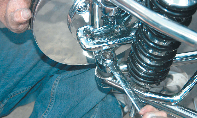
The lower sway bar bolt was connected using an Allen wrench on the bolt and a 9/16-inch wrench on the Nylok nut.
The upper sway bar bolt was secured with a large Allen wrench. This bolt should also be installed with antiseize on the threads.
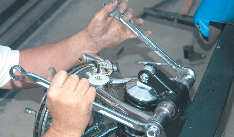
The upper A-arm bolts were secured. A 15/16-inch box-end wrench and an open-end wrench were used to connect the Nylok nut.
The lower A-arm nut and the Nylok nut were secured with 15/16-inch box-end and open-end wrenches.
The upper shock bolt was secured with an Allen wrench and a 3/4-inch box-end wrench.
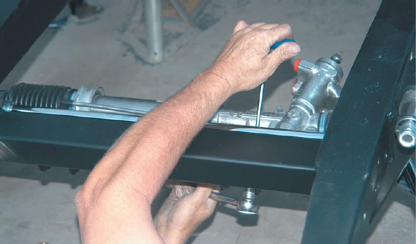
The power rack-and-pinion unit was connected to the crossmember brackets with four button-head Allen bolts and four Nylok nuts.
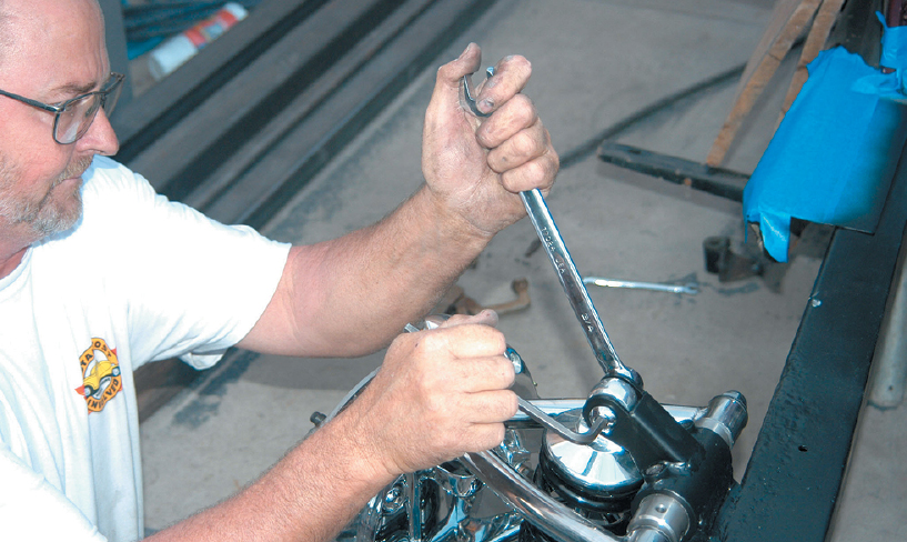
Using a T-handle Allen wrench and a 9/16-inch open-end wrench, the rack-and-pinion unit was secured to the brackets.
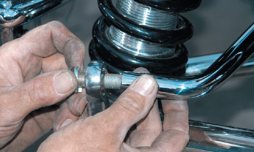
The rack-and-pinion ball-joint end was screwed onto the shaft. Note that the shaft was coated with antiseize because the ends will have to be adjusted to set the toe-in.
The rack-and-pinion ball joint was connected with an 11/16-inch wrench. This is a castle nut, so a cotter key must be installed.
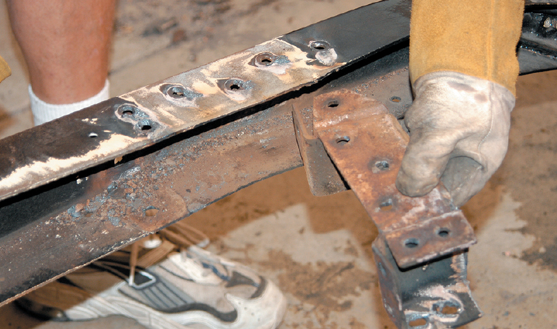
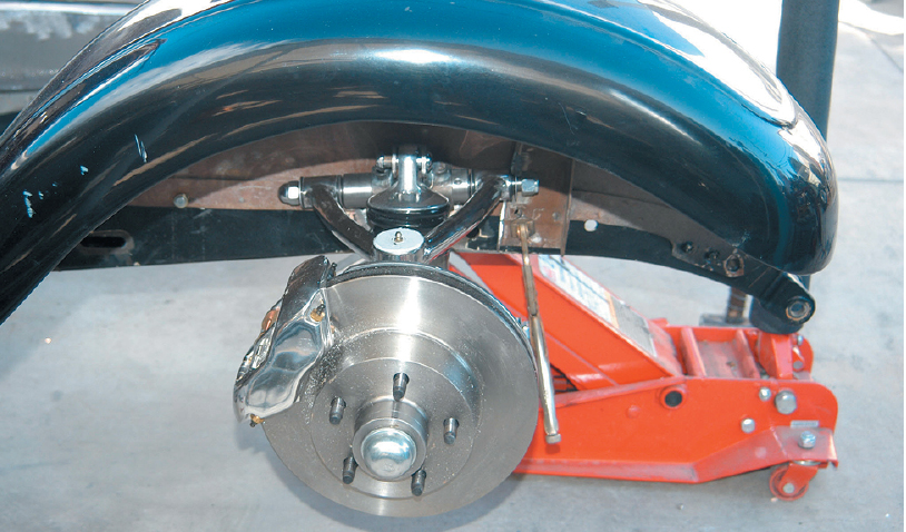
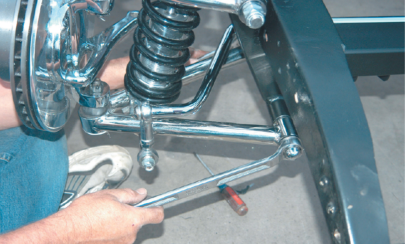
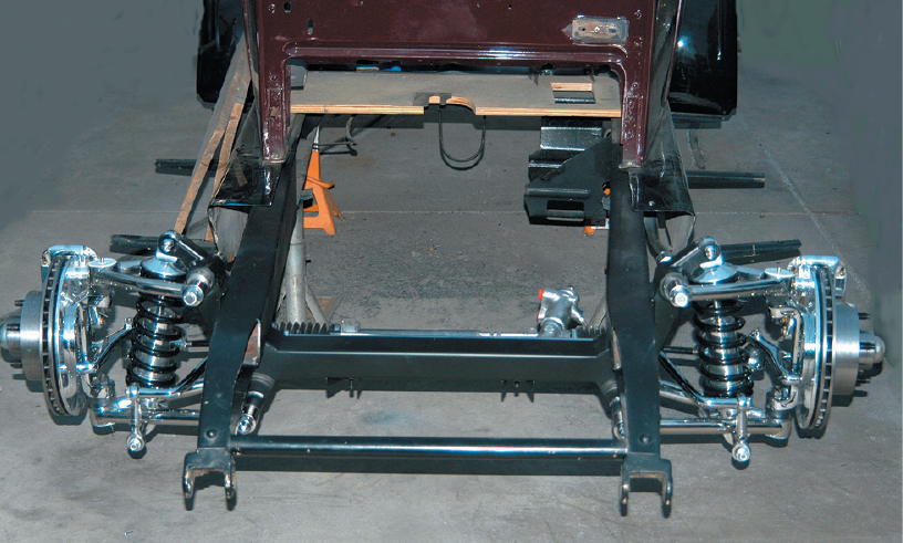
Here’s the unit finished and ready to go. It looks great, will drastically lower the front end of the Chrysler and will ride great. One of the next steps will be the removal of the front spring brackets at the front of the frame.
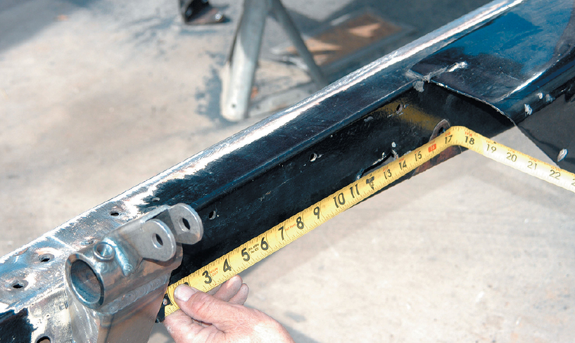
The problem Lawson foresaw was that the car was a Chrysler, and street rod companies donʼt build suspension systems for old Mopars. Hopefully there was something close that could be adapted to the Chrysler frame. The frame was measured, and it was found to be dimensionally almost the same as a ʼ33-ʼ34 Ford. He called Total Cost Involved and told the salesperson that he was building an early Chrysler, and the salesperson told him they could custom make an IFS crossmember for the car, using a few important measurements. Dream Cars provided the company with the measurements, and in about two weeks a load of boxes arrived with everything needed to upgrade the old Chrysler. If you are into the unusual, this is how it went.