TheAutoBuilder.com

Edit Template

GOING IN THE TANK

The Finer Points of Gas Tank and Fuel System Design

Author

Picture of Lane Anderson

Lane Anderson

Story & Photography

More than one technical article has been written about gas tanks. Some of these articles would lead you to believe that a foam-filled fuel cell is the only solution, and others give you the impression that any tank will work as long as you have a high-dollar, killer fuel pump. However, we believe that the truth lies somewhere between these two opinions.

Your gas tank is only the first part of the fuel system. As more streetcars are equipped with fuel injection and the required higher-pressure fuel pumps, having the components of the fuel system to work in unison becomes more important. As fuel pressure and volume requirements increased, mechanical fuel pumps disappeared, and electric pumps went from an aftermarket item to a standard in the gas tanks of The Big Three.

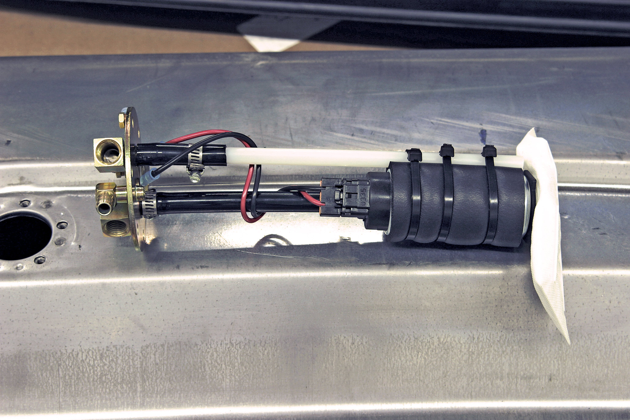
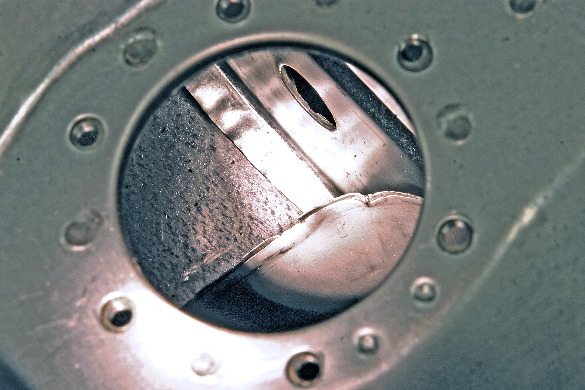
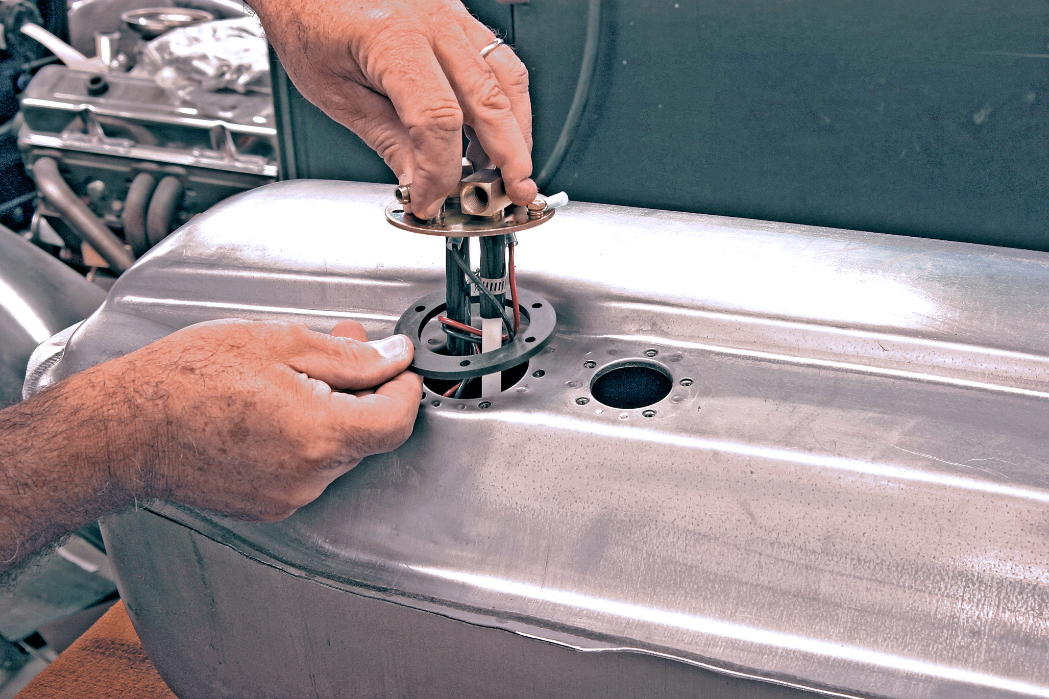
Higher fuel pressure requires the fuel pump to expend more energy, and with energy comes heat. By putting the pump into the tank, the gasoline in the tank is used to keep the pump cool. Using a flammable liquid (gasoline) to cool the electric pump may sound scary, but remember that only the vapor is flammable-not the liquid. The pump needs to be immersed at all times, including during hard turns, sudden stops and violent accelerations. To keep the liquid around the pump, it becomes necessary to have baffles around the pump. These baffles function like a tank within the tank. It is also not a good idea to uncover the fuel pickup and allow air to be pumped into the fuel lines. Some aftermarket fuel pumps that mount outside of the gas tank recommend adding a 2- or 3-quart accumulator (mini-tank) to prevent starvation of the pump.

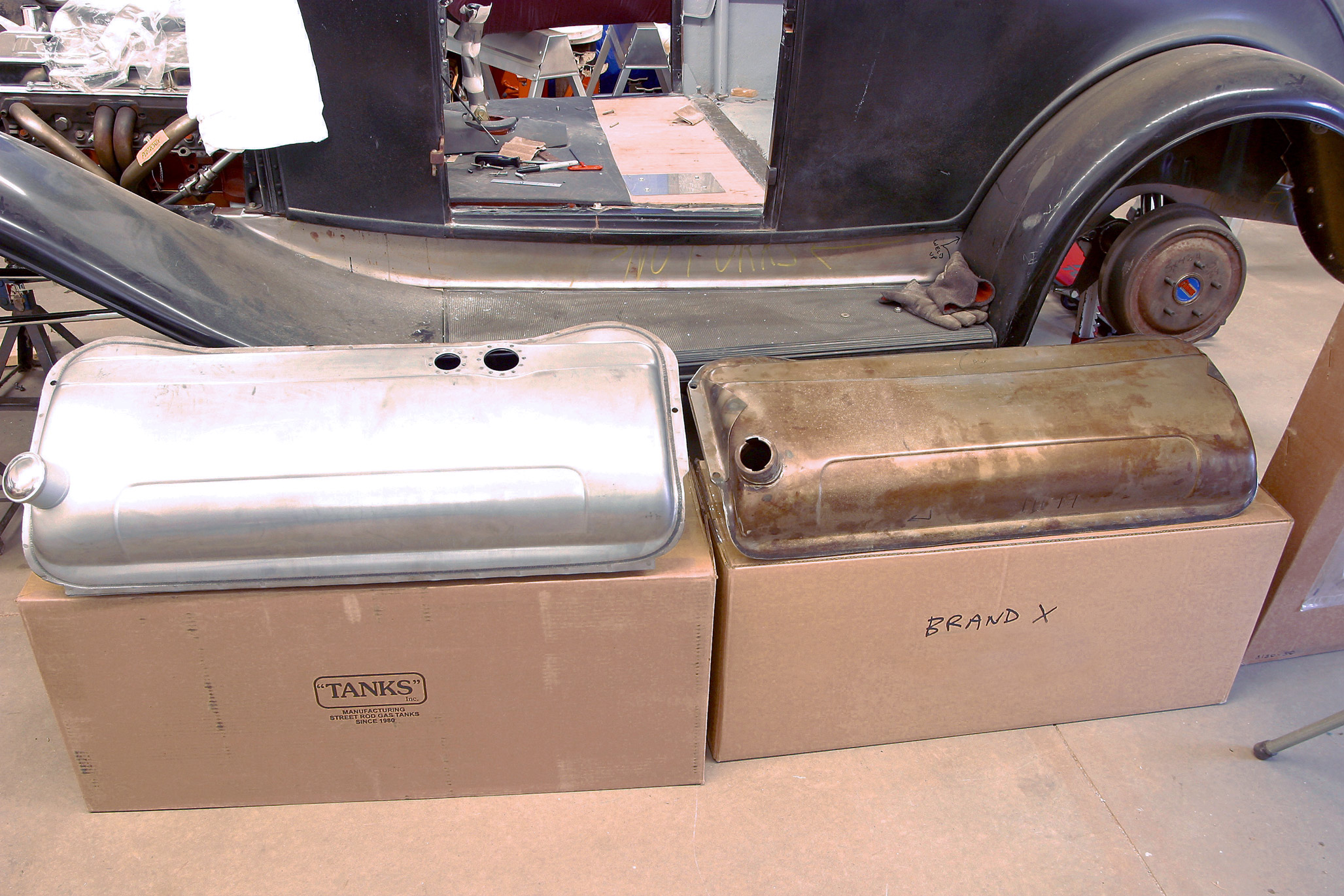
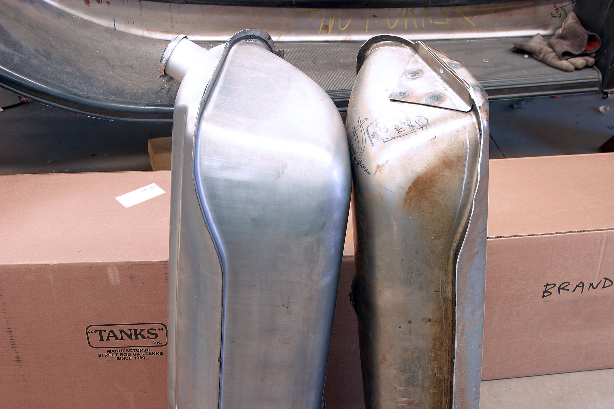
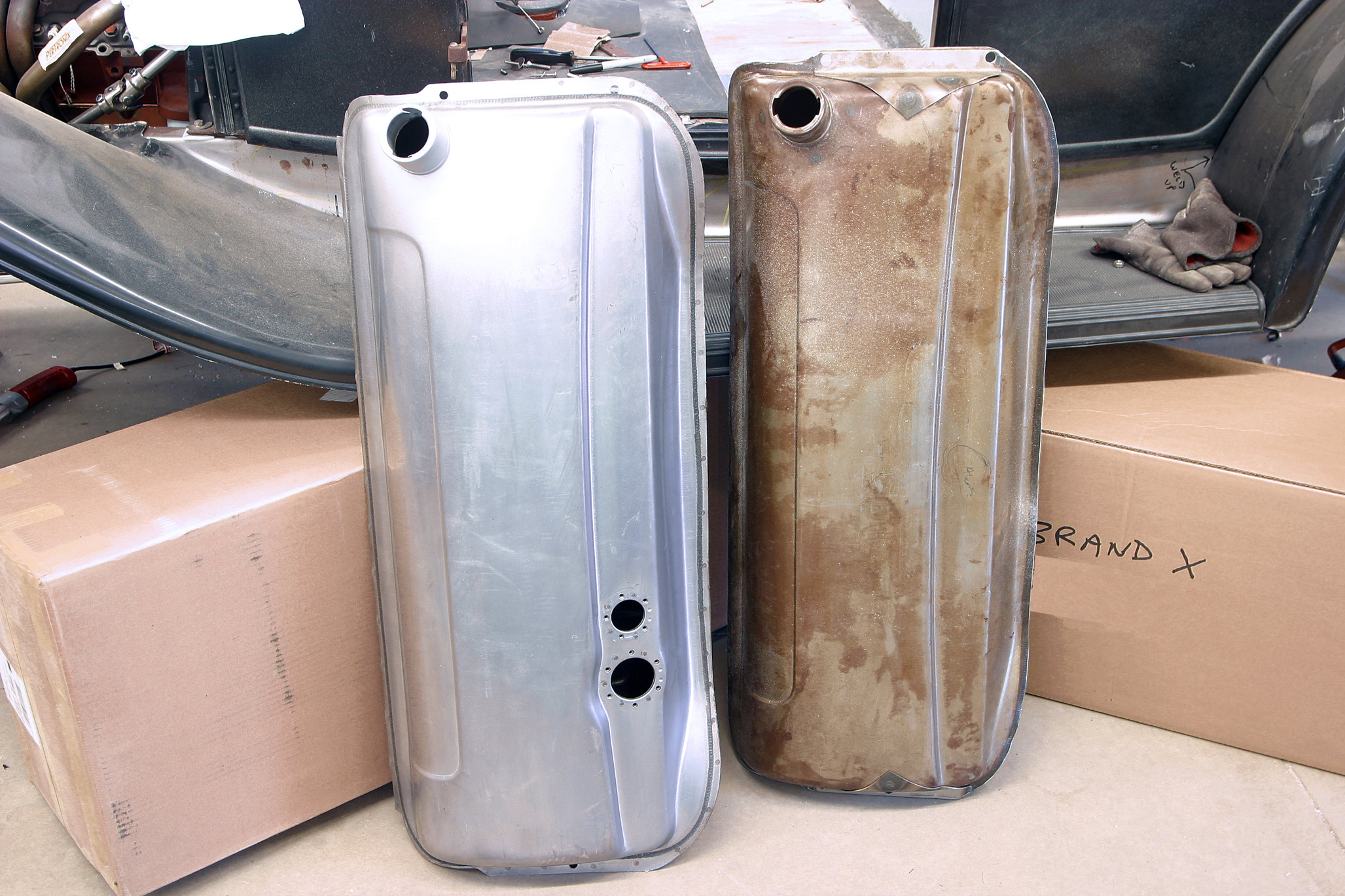
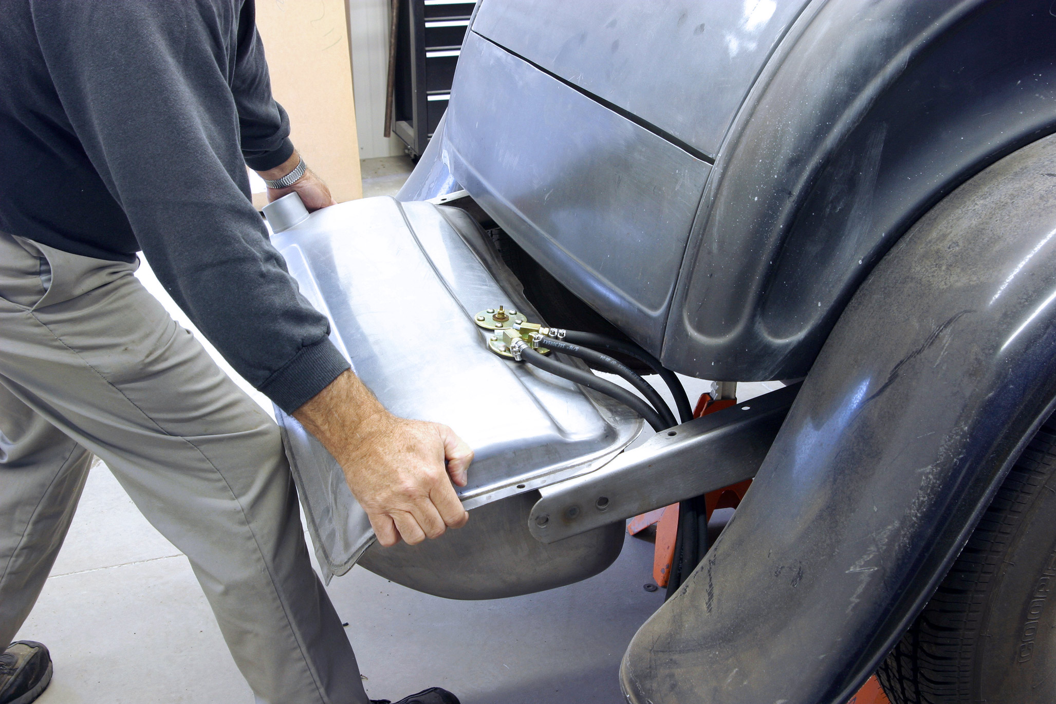
We selected Tanks (320/558-6882) because they offer several styles of tanks for many popular applications and several different submerged fuel pumps for almost any application.

Just for ’32 Fords, Tanks offers standard and oversized tanks (11- or 16-gallon) in mild steel, stainless steel, polyethylene and galvanized options. They offer three different fuel pumps, each having a different output flow to match your needs. They also offer fuel pumps with a self-contained reservoir for use in many of the polyethylene tanks. With so many options, good technical support becomes important, and Tanks has an excellent technical support staff.

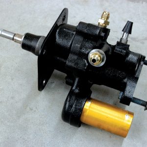
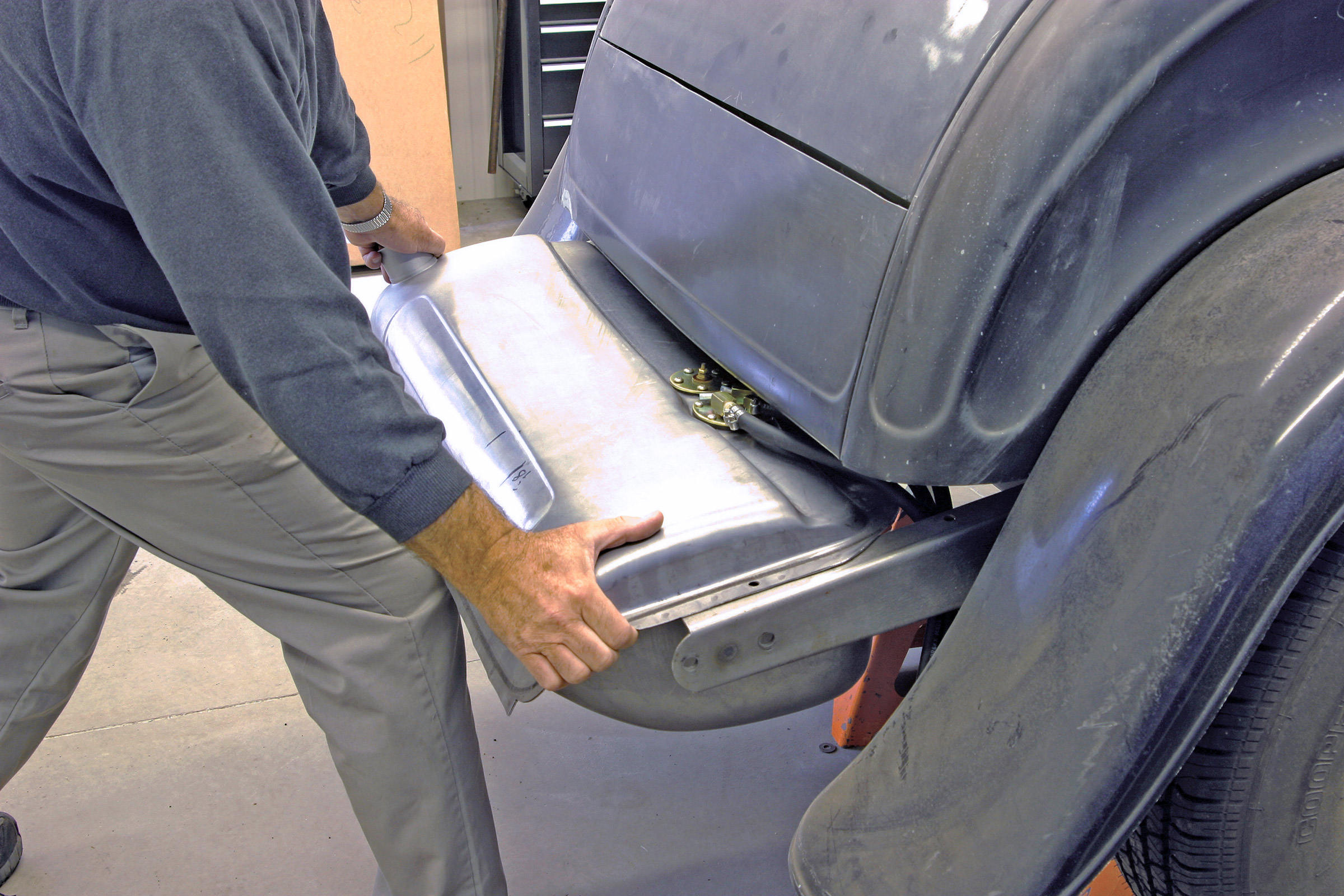
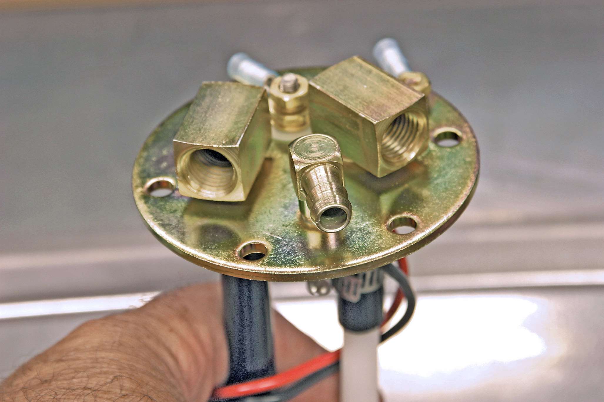
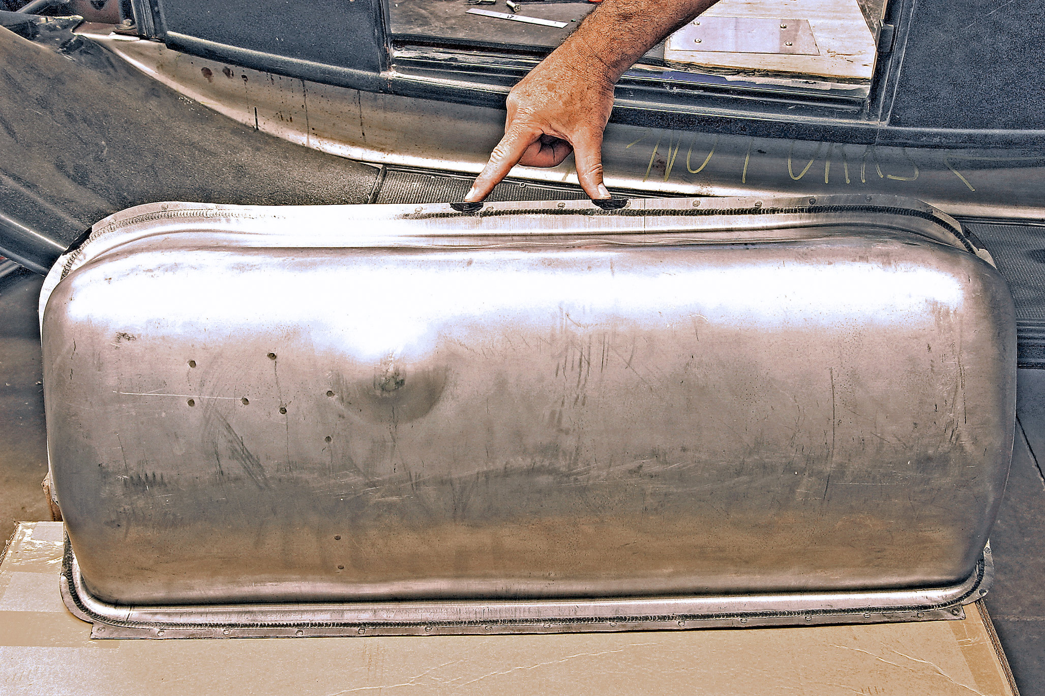
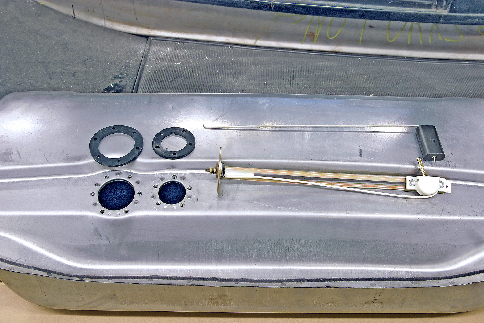
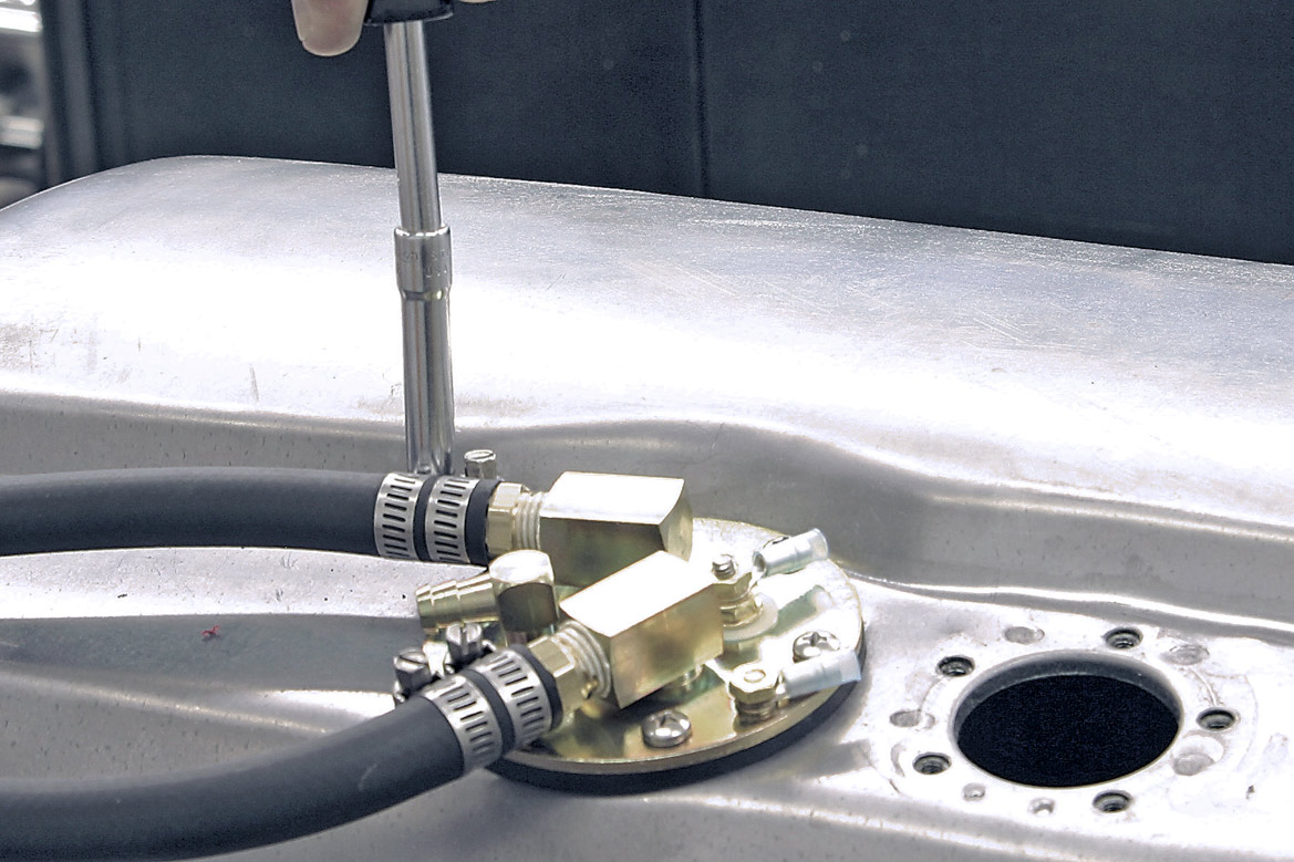
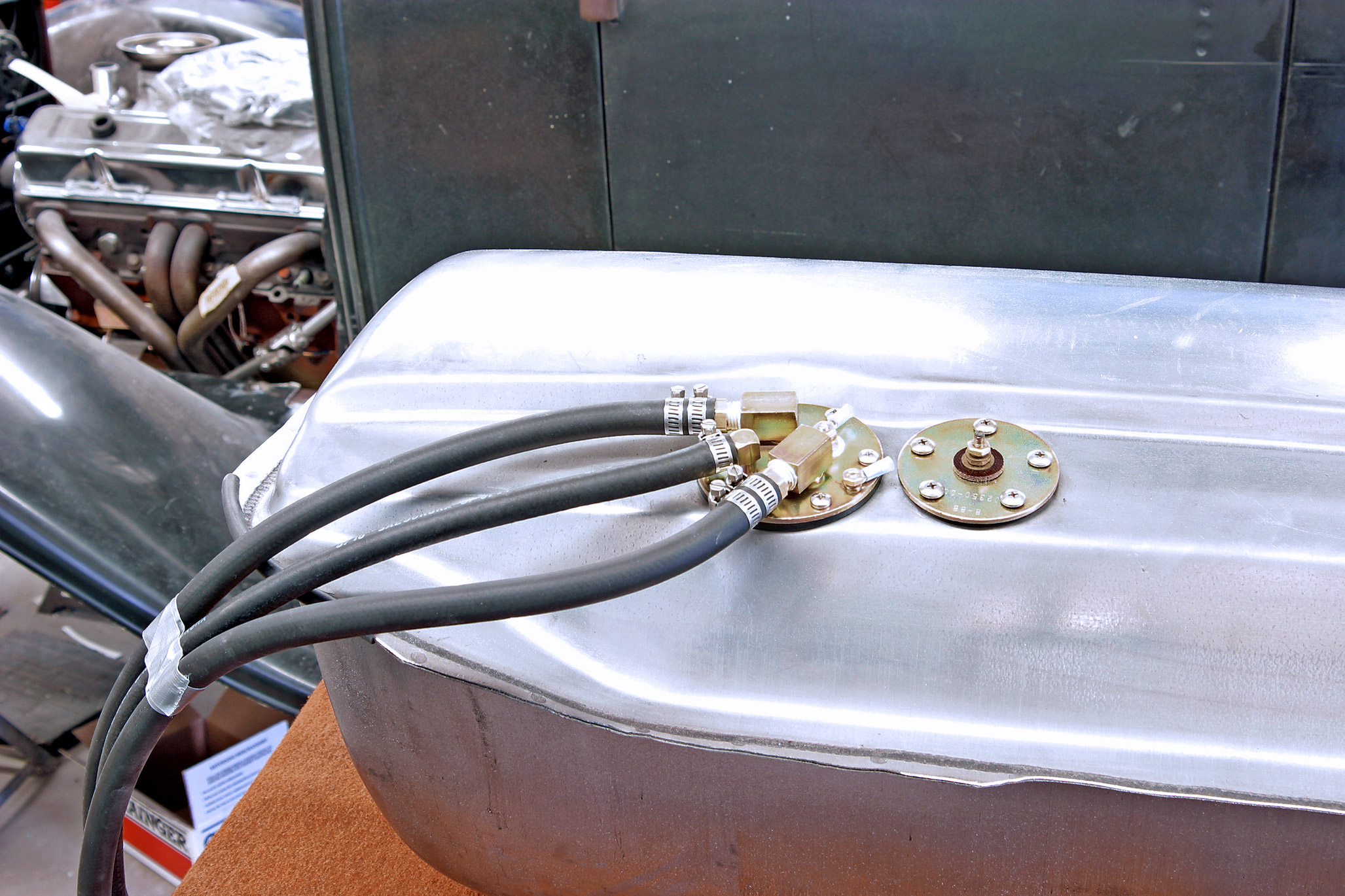
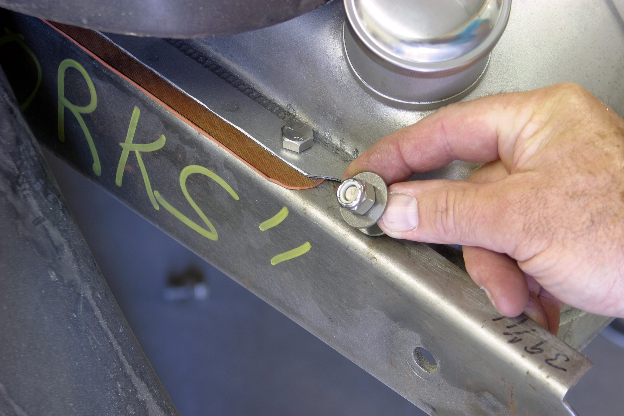
We selected an oversized, plated, steel tank with internal baffles and a submerged fuel pump that matched the requirements of our TPI fuel injection system. Tanks lists three different fuel pumps for the various volumes and pressure requirements.

The gas tank may be the biggest single part of the fuel system, but the smallest part is just as important. Let’s take a tour through the rest of the fuel system. Gas hose isn’t just gas hose anymore!

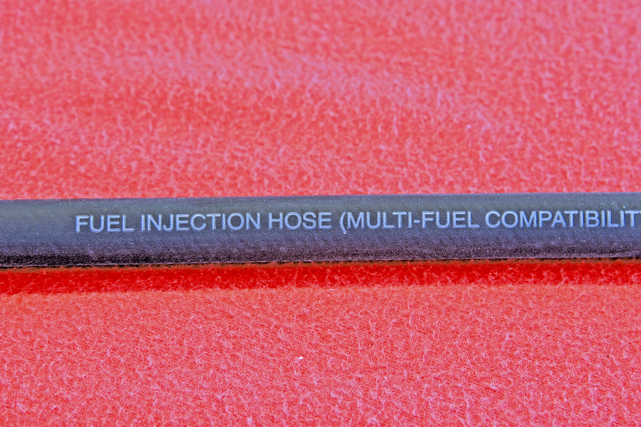
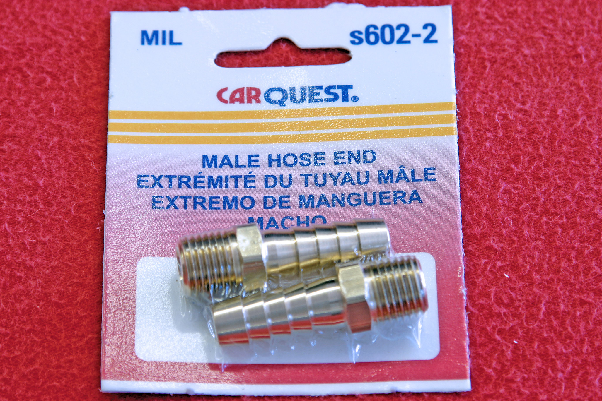
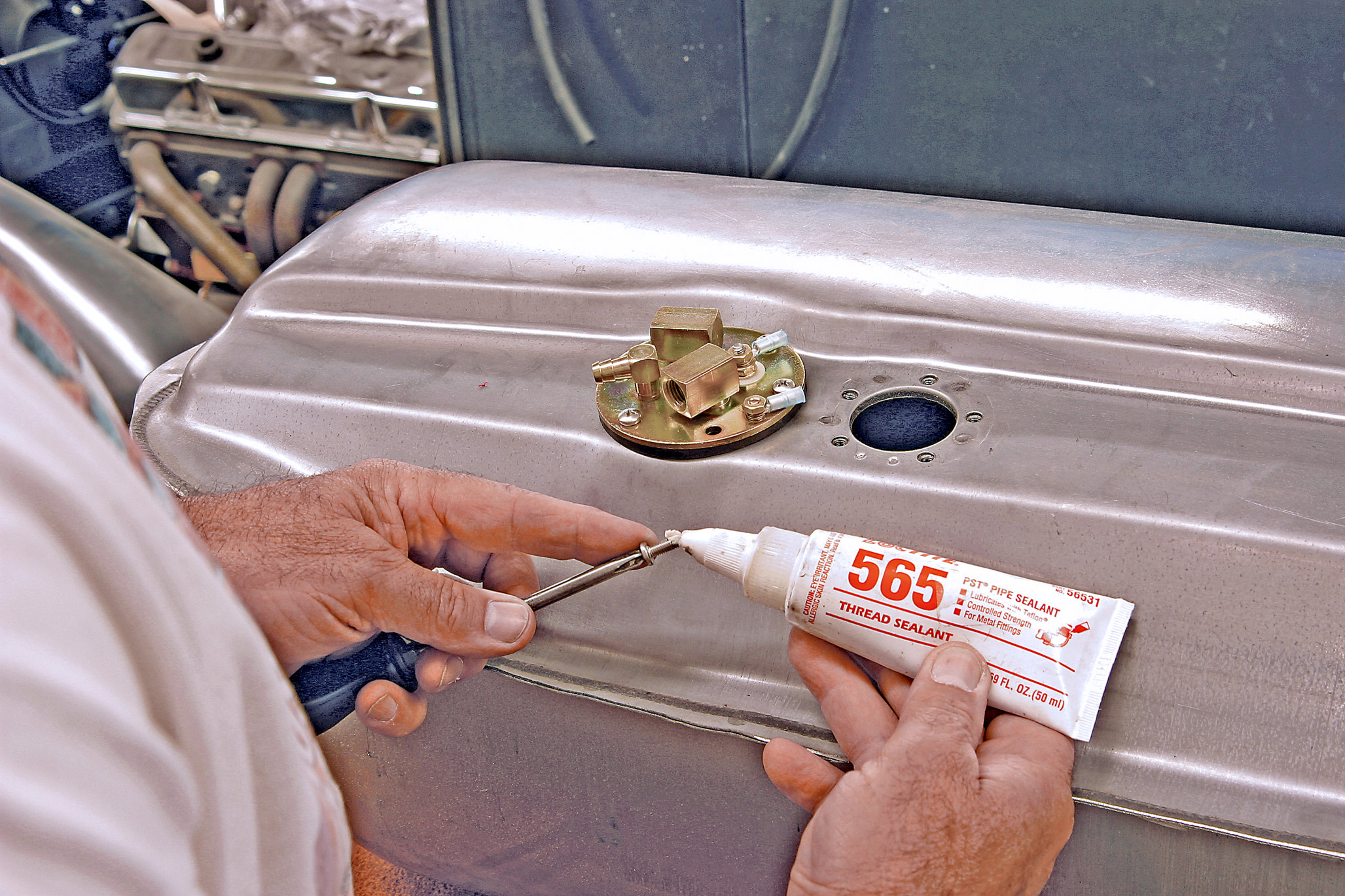
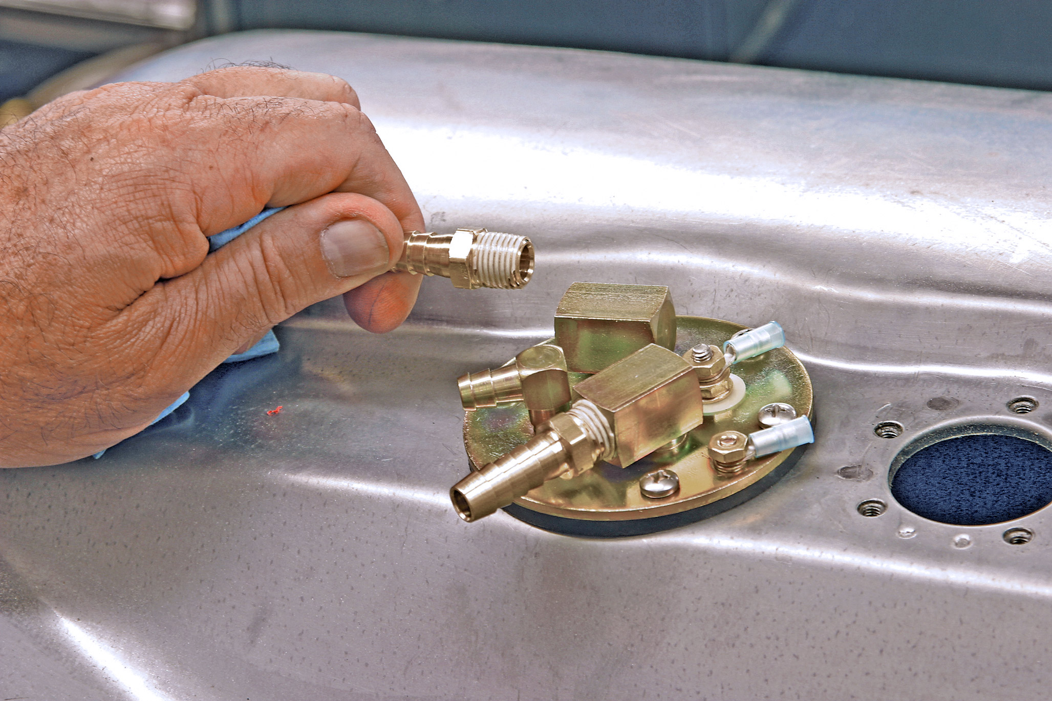
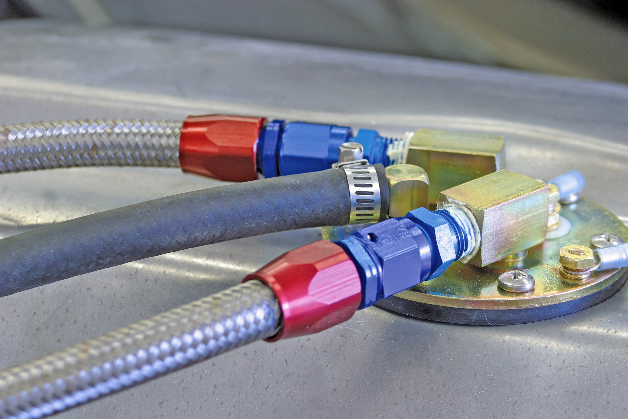
The top-of-the-line option is braided stainless steel hose. This is the best-looking option, but the hose and related fittings can get pricy really fast. It is not necessary to use the high-dollar braided hose, but the old-style, low-pressure fuel hose is definitely not suitable. Your local auto parts store can provide you with a black, flexible, high-pressure fuel hose. This hose will be clearly marked “fuel injection.”  The fuel return line also requires the high-pressure hose. The old-style, single-rib hose barb fittings are no longer acceptable. Multiple-rib fittings with two hose clamps will handle the higher pressure.

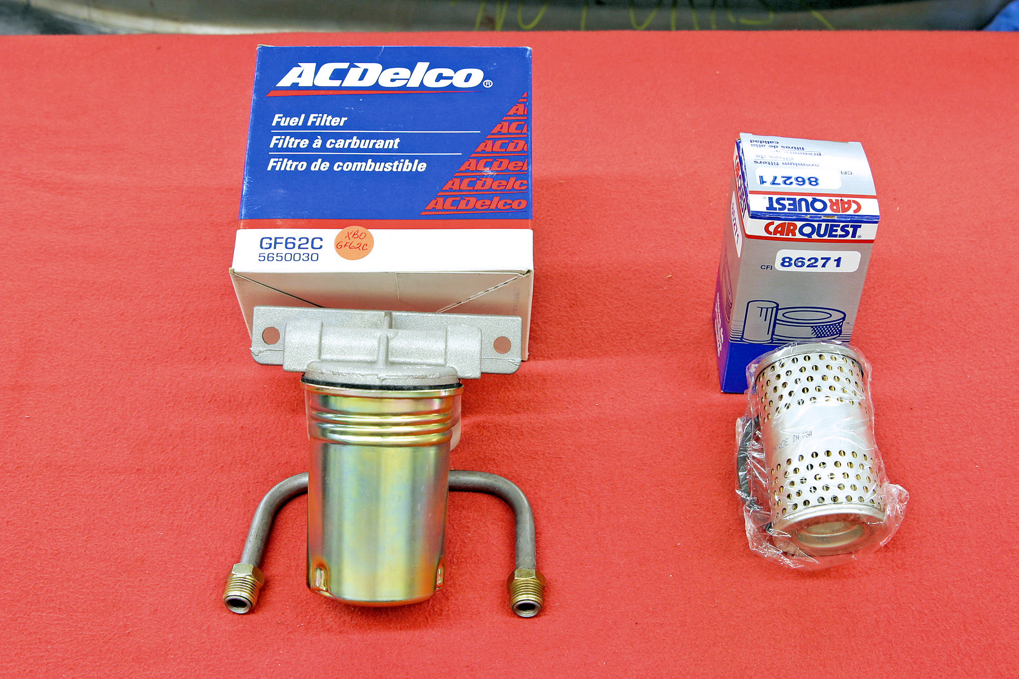
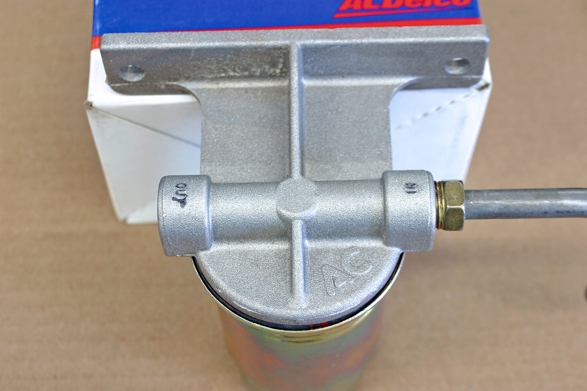
The next component to consider is the fuel filter. The old-style inline plastic filter should not be used for two reasons. First, those filters were not designed for the higher pressure. Second, they cannot handle the volume required for a fuel injection system. For years, the important number was fuel pressure, but that all changed in 1965, when GM introduced the Q-Jet carburetor with its small fuel bowl. From that point forward, the important number became fuel volume.

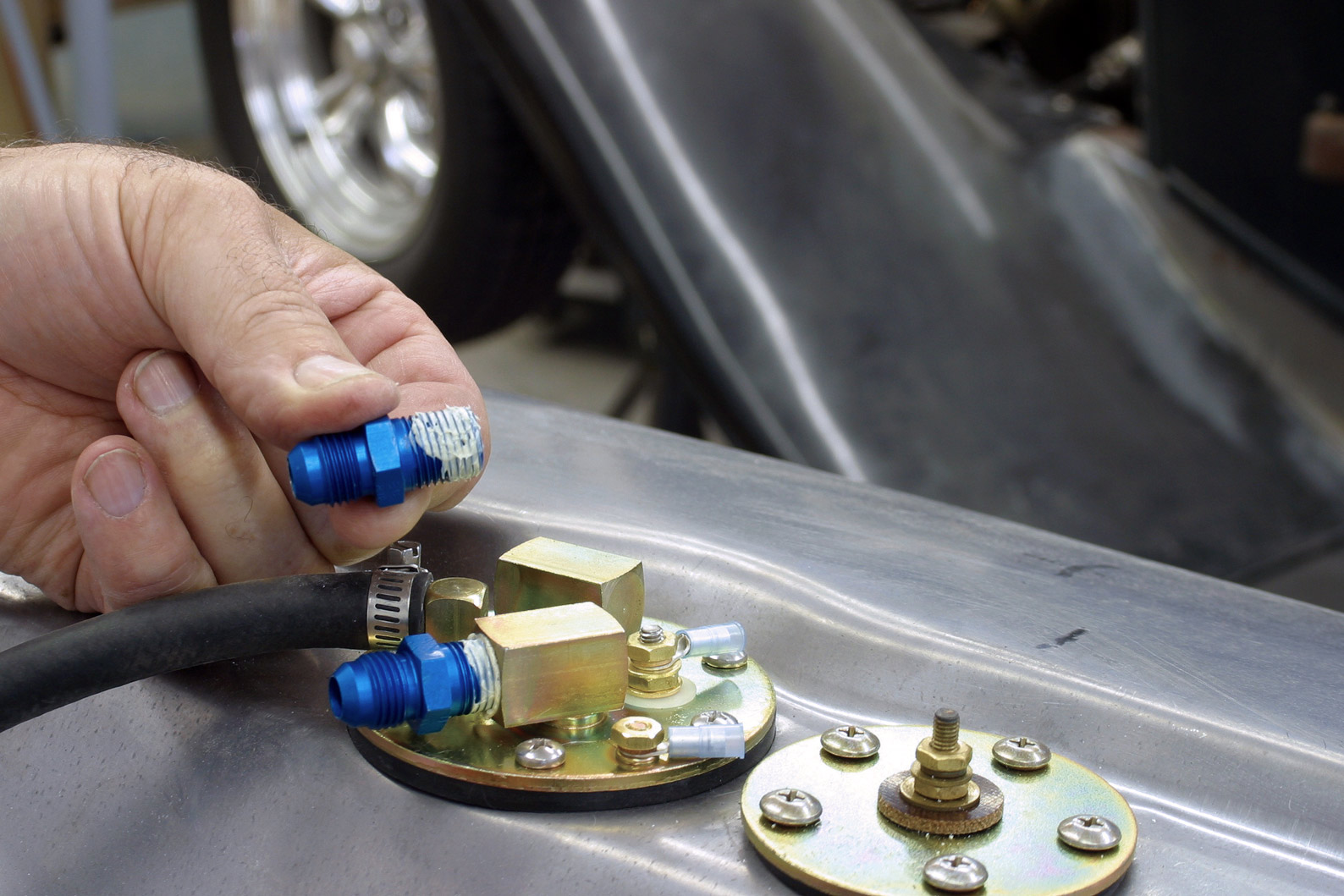
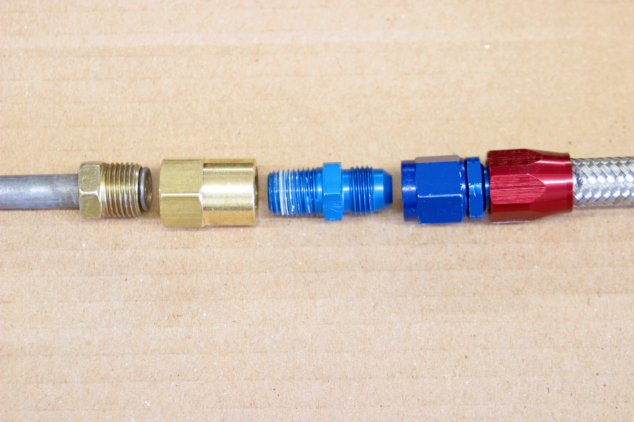
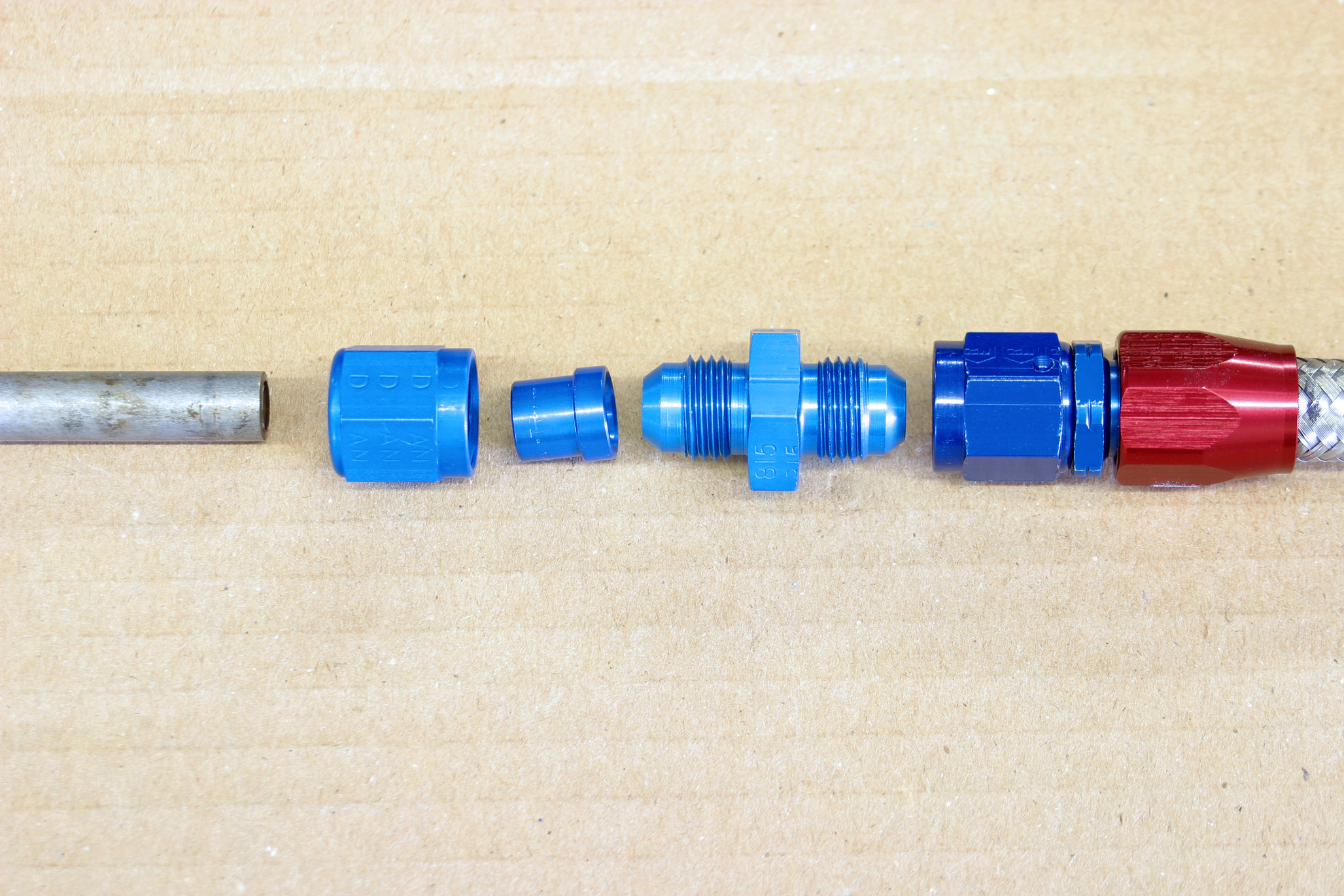
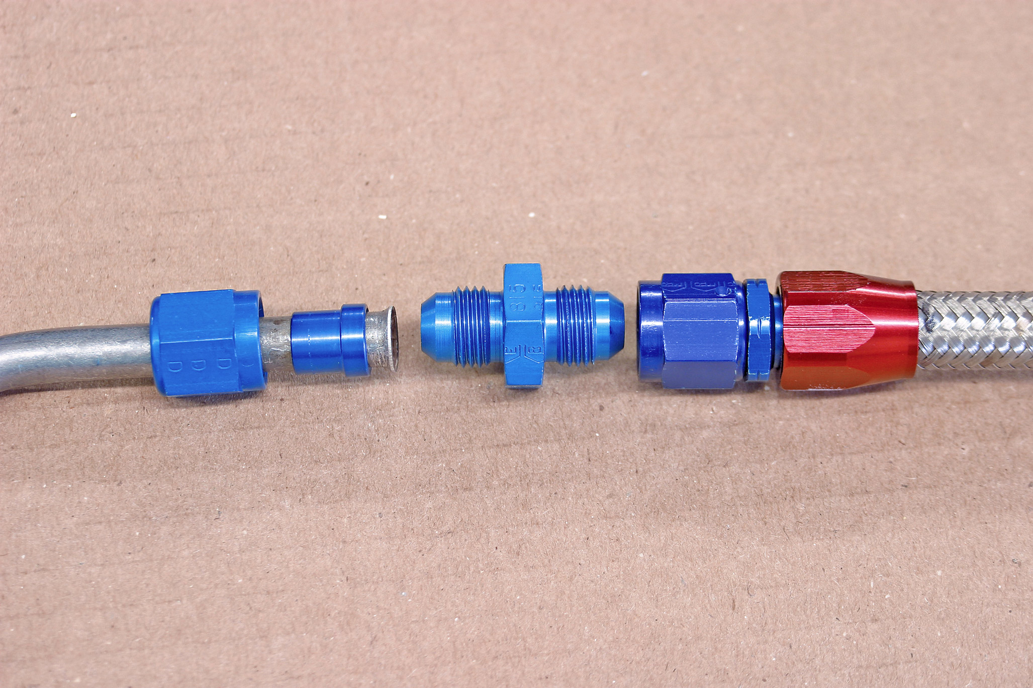
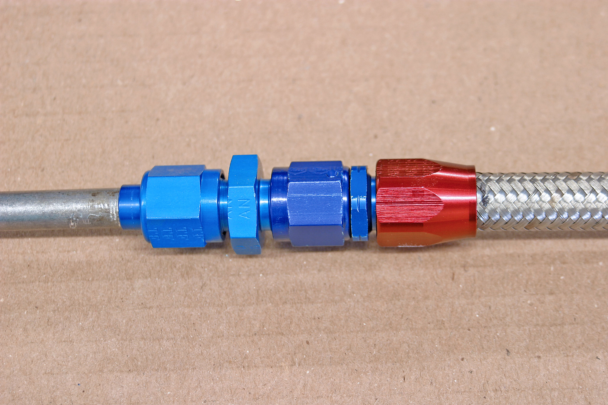
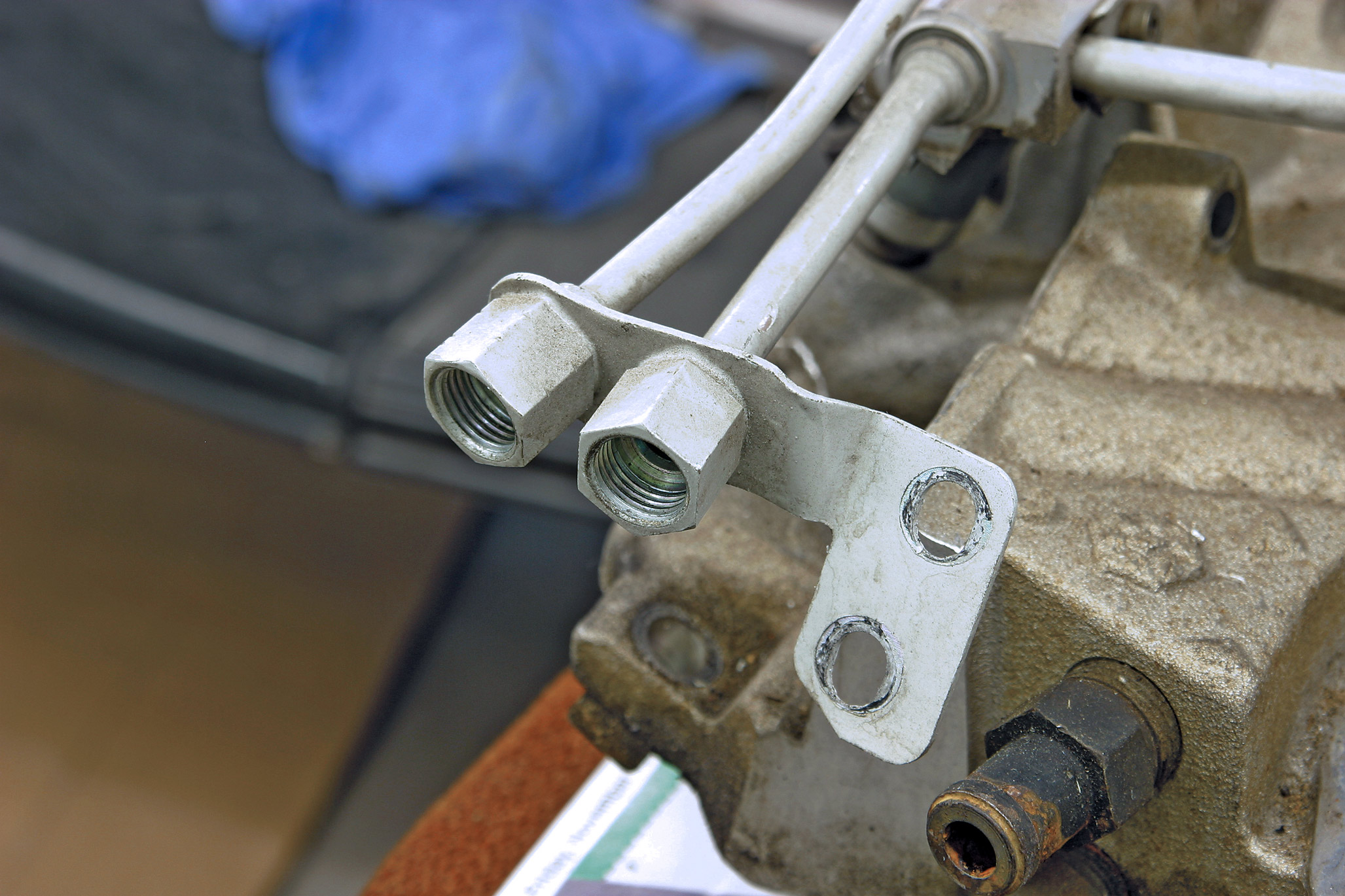
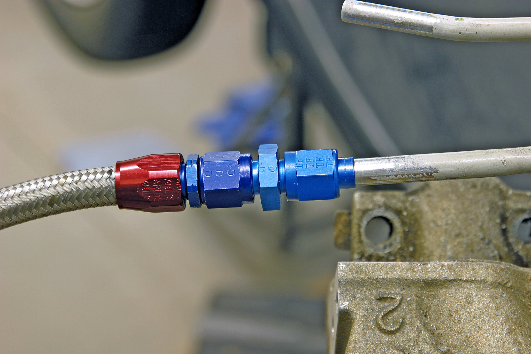
When you get the fuel supply and return lines to the fuel rails on the engine, you need fittings to connect them. We called Street & Performance (479/394-5711) to ask what we needed to complete our connections. The crew at S&P advised us that the majority of OEM fuel injections use O-ring fittings of a 14mm or 16mm diameter, and S&P can supply adaptor fittings to connect most metric ports to #6 AN fittings.

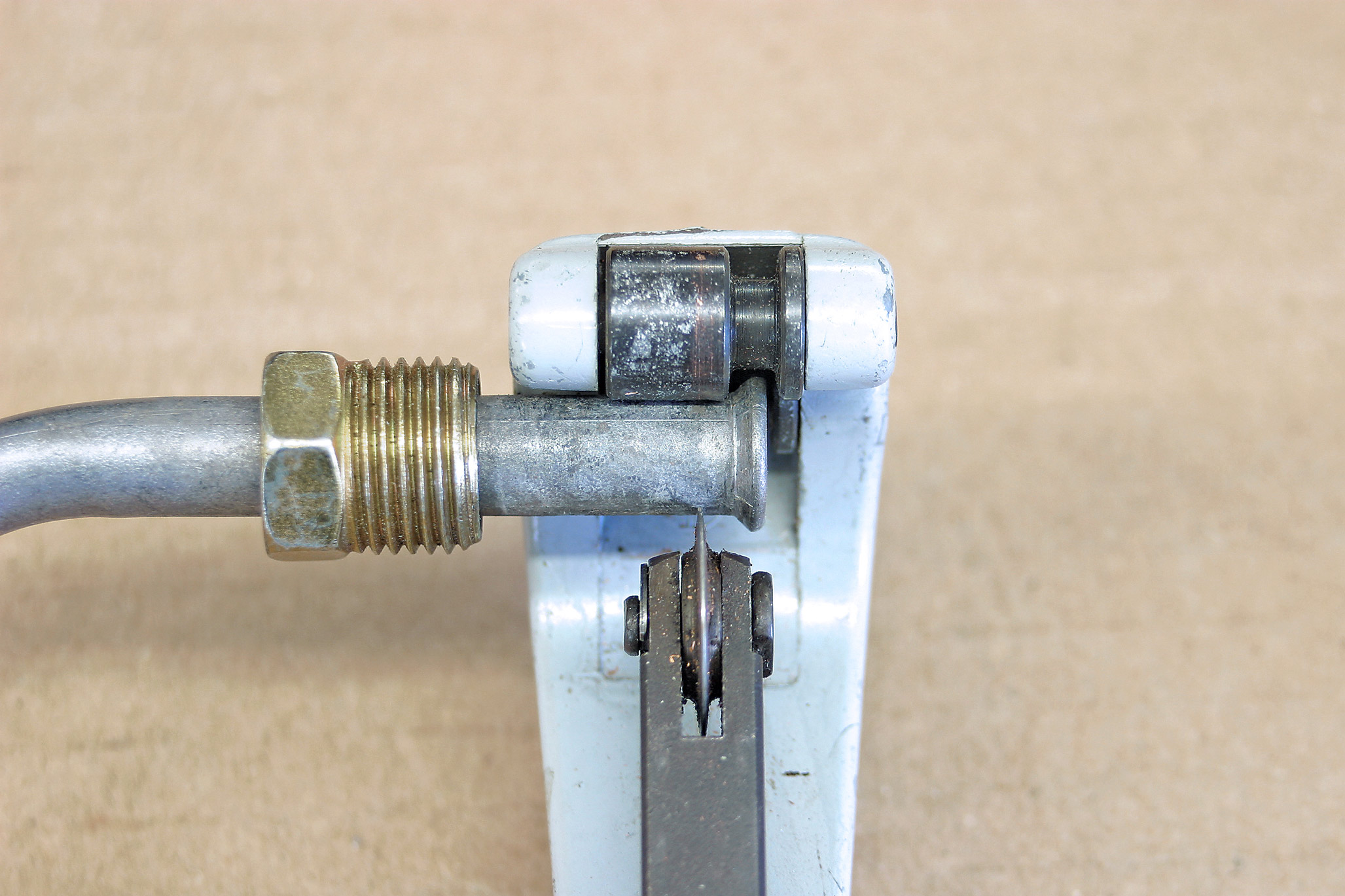
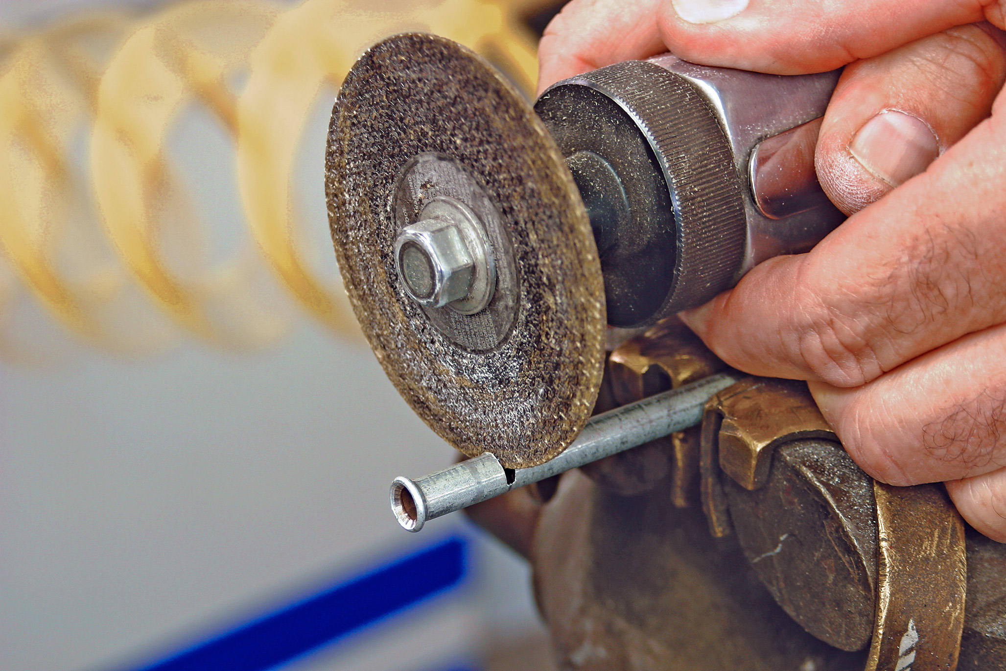
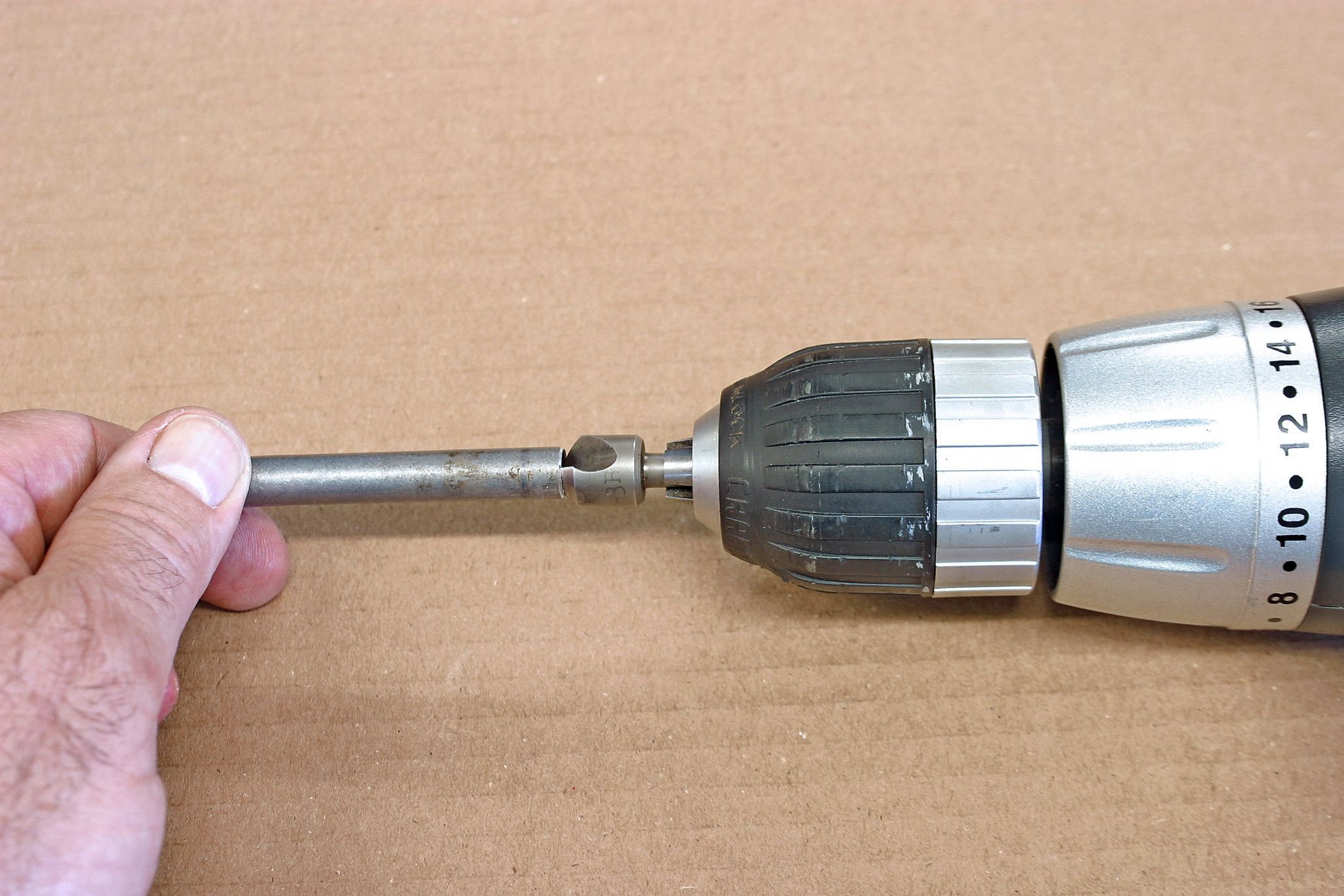
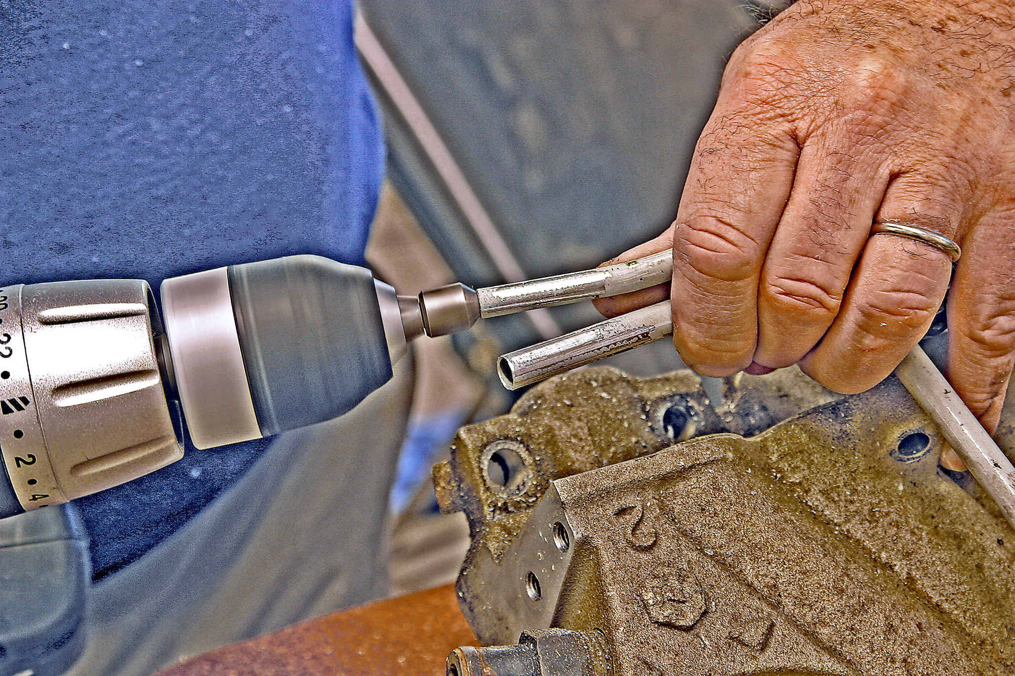
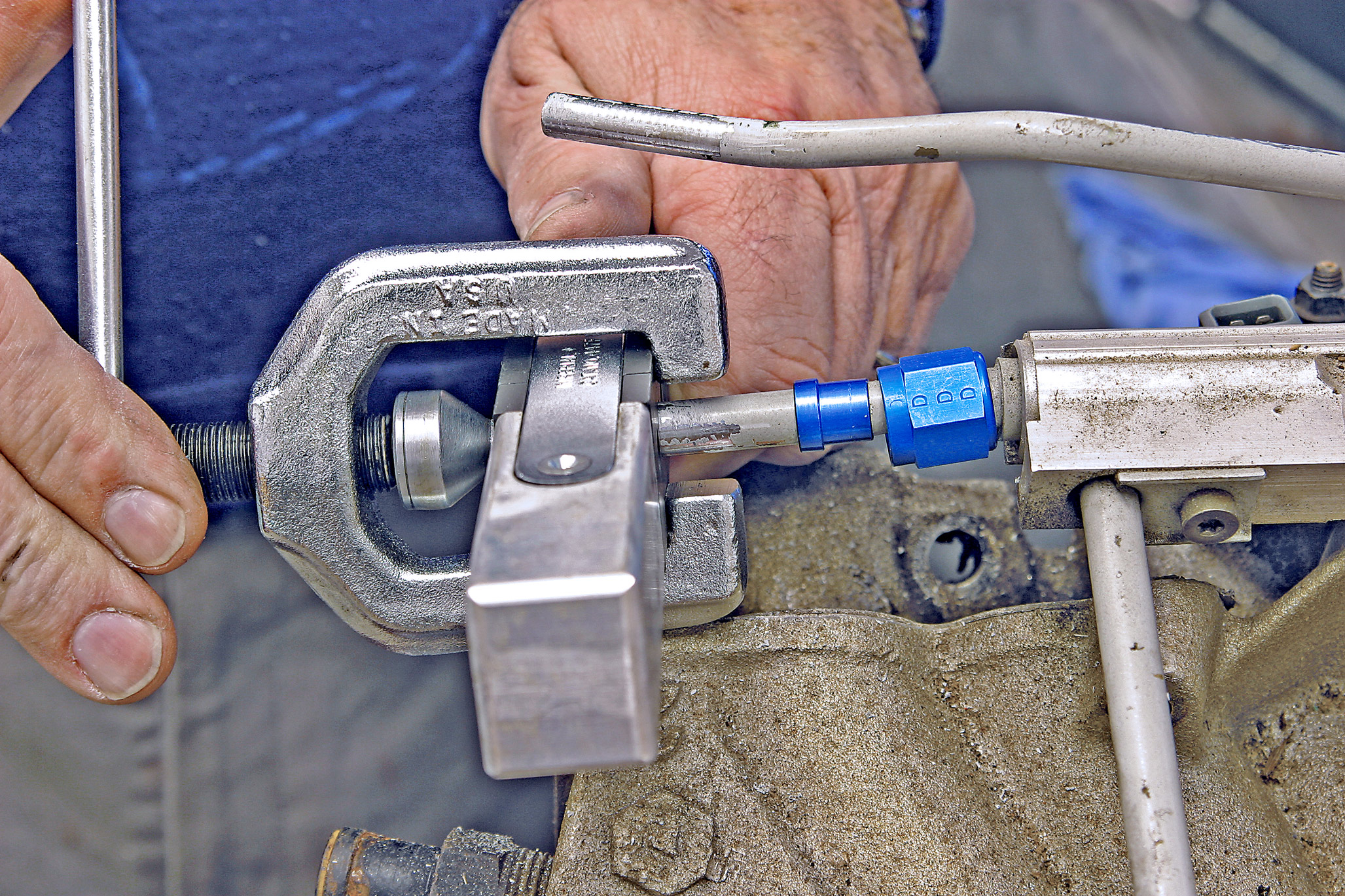
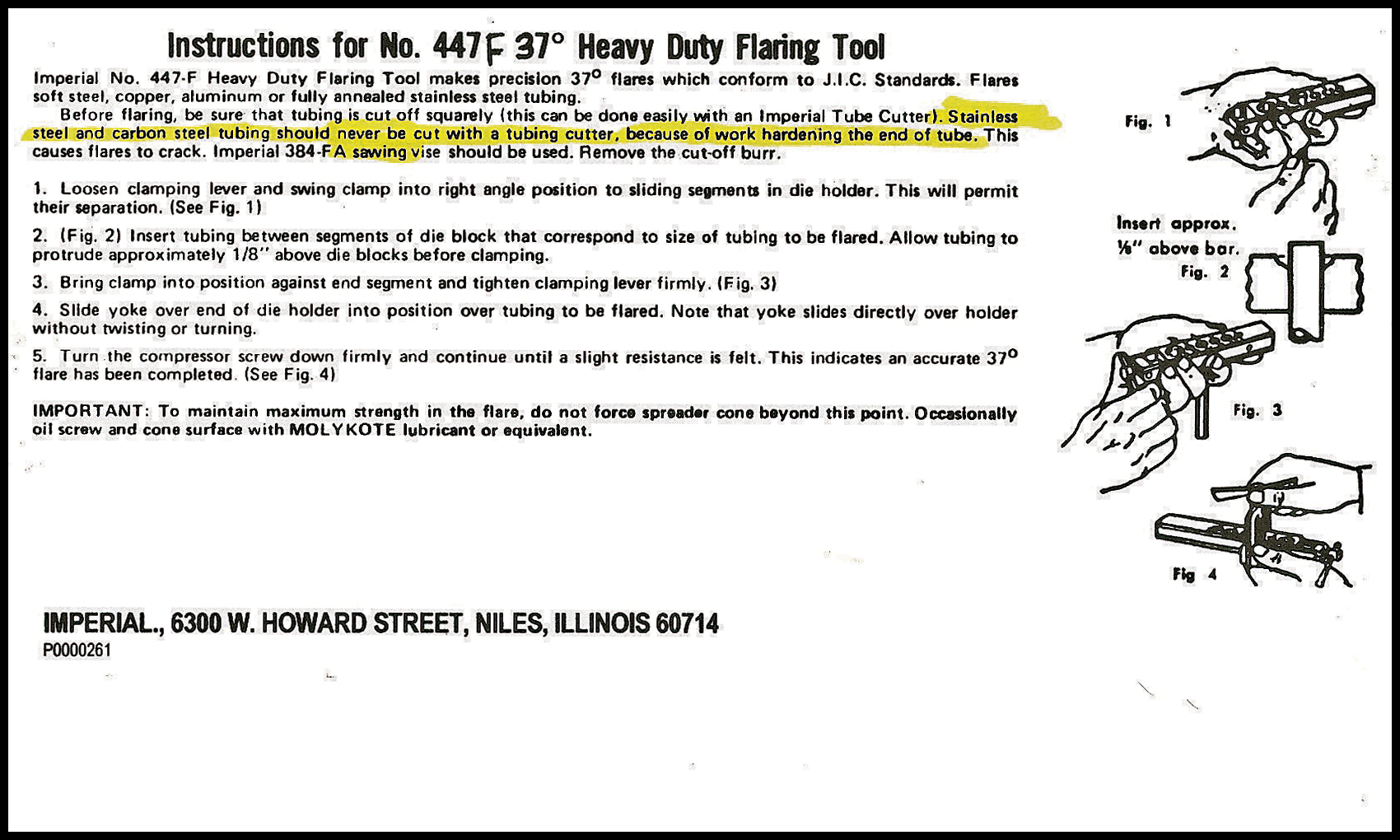
The TPI system has a 3/8-inch supply line and a 5/16-inch return line, and there was enough line between the fuel rail and the metric fittings that we could cut the factory fittings off, form 37-degree flares and connect a #6 AN union directly to each line. You could buy a lot of adaptors for the price of one flaring tool, but we already had the flaring tool.

The return portion of the system runs from the return line exiting the fuel rail, through a #6 braided hose, to the 3/8-inch steel line and back to the fuel tank. When the return line enters the tank, it should discharge the returning fuel at the bottom of the tank below the liquid level. Dumping the fuel into the top of the tank will cause unwanted splashing, aeration, static electricity and unwanted vapors.

Gas tank venting is not something that you buy, but it is a very real part of your fuel system and should not be ignored. Tanks and other suppliers can help you make good decisions regarding the routing of the vent hose and/or use of a rollover check valve. You should also think about the fact that gasoline weighs approximately 6 pounds per gallon, so 14 gallons of gas will weigh 84 pounds.  That is a lot of weight to be sloshing around inside your fuel tank. Baffles in the tank will greatly reduce the sloshing, but the tank needs to be securely anchored. When the fuel has returned to the tank, the fuel system is complete.

Our new tank from Tanks (320/558-6882) is on the left, and a ’70s reproduction tank is on the right. The old tank may have some historical value, but because it is too tall to fit into the car and has no baffles or provisions for gas lines, vent lines or a gas gauge sender, it has no value to us. It was more cost-effective to purchase the new tank with the fuel pump.
We opted for the 16-gallon tank to increase our cruising range. The tank is deeper than an original, but the increased height is not apparent when the tank is installed.
The new tank from Tanks has reinforced mounting surfaces for the fuel pump and the gas gauge sending unit. The picture does not show how much crisper the details are on the new tank, but there is a major difference.
Our first thought was to use the old tank and install a new neck that would accept a sealed gas cap to prevent sloshing gas onto the painted exterior of the tank. Shown here is $60 worth of neck and caps. This money was wasted because we tried to do things cheaply.
With the new tank, we purchased the correct fuel pump to work with the TPI injection setup. This assembly incorporates the fuel pump, supply output fittings, vent line fitting and return line fitting and down tube that extends the return line to the bottom of the tank. With this system, there is no need to cut and weld additional inlets/outlets on the tank.
This is the top of the fuel pump assembly. The threaded ports are the supply and return lines. The hose barb is the vent line. In the background are the electrical terminals for the gas gauge and ground wire.
It’s hard to take a picture inside a gas tank, but this shows the vertical baffle and a corner of the tank-within-a-tank that will surround the fuel pump.
The roadster that will be home to this tank has a buggy spring rear suspension. This required us to file two notches in the front lip of the tank to clear the spring-mounting U-bolts. Do not cut or grind into the weld line that joins the two halves of the tank.
The tank accepts the standard aftermarket fuel gauge sender unit. We followed the directions and cut the sender unit to the required length. Tanks supplies Viton gaskets for both openings. No more cork gaskets!
Any flexible hose used in the fuel system should display this label. This hose is flexible, just like old-fashioned gas hose, but it is capable of handling the higher fuel pressures.
Hose barbs, flexible hose and hose clamps are acceptable in the fuel system if you use multi-flute hose barbs (as shown) and two hose clamps per barb. Do not use the old-style single-flute fittings.
This is how your flexible hose attachments should look. Each hose/barb joint should be secured with two screw-type hose clamps of the correct size.
The fuel pump is lowered into its opening; don’t forget the gasket. The bolt pattern is not symmetrical, so the pump will only bolt down in one position.
Because the threaded mounting plate has through holes and the assembly has a dedicated ground wire, we used a gasoline-rated thread sealant on the #10-32 mountings screws.
We also used the same thread sealant on the 1/4-inch NPT threaded fittings.
In a flexible hose installation, we have the supply and return lines secured to the tank fittings with two clamps. The vent line is secured with one clamp.
If we are going to use braided flex hose, we will install a 1/4-inch NPT by a #6 AN adaptor into the tank inlet and return ports. Use thread sealant on the 1/4-inch NPT threads in this application as well.
The AN fitting on the hose will then screw directly onto the adaptor. The vent hose outlet is not threaded but is a hose barb, and since that line will not see any fuel pressure, one clamp is fine. If you want to use braided hose for the vent line, you will need a hidden clamp-type hose end fitting.
We prefer to attach all of the lines to the tank and then slide the tank in place. The ground wire and gas gauge wire are accessible through the access port in the trunk floor.
Next in line is the fuel filter. We are using a GF62C A/C filter assembly. This filter has a replaceable element (PN 86271), and the lower portion of the housing screws off to change the element with no tools required. This filter assembly is capable of handling the pressure and volume of a fuel injection system.
The top view of the filter housing shows the mounting holes. The in and out ports are clearly marked. Yes, there is a difference! The two ports are 3/8-inch inverted flare. We will run a short section of flared 3/8-inch diameter steel line from the filter to our braided hose.
The steel line is on the left. The brass adaptor is 3/8-inch inverted flare by 1/4-inch pipe thread. The blue adaptor is 1/4-inch NPT by #6 AN.
The other option is to cut the flare off of the steel line, reconfigure it to a 37-degree flare and use a #6 AN nut and sleeve to mate to the #6 adaptor.
This is how most street rodders cut steel and stainless steel tubing. Because the cutting action of the tubing cutter will work-harden the tubing at the cut and increase the chances of cracks in the flares, this is not the recommended method.
A fine-blade hacksaw or a cutoff wheel are two methods of cutting tubing that do not work-harden the tube end.
Regardless of the flaring angle, the directions will tell you to “deburr and chamfer the end of the tube before flaring.” A battery-powered variable speed drill and a countersink bit will do an excellent job. Do not attempt to skip this step.
Here, we have our steel line with the AN nut and sleeve installed behind the 37-degree flare.
Here is the finished connection with the steel line flared and connected to the AN adaptor and hose.
When you get to the TPI unit, you find metric O-ring fittings. Street & Performance (479/394-5711) sells adaptors to fit most 14mm and 16mm fittings, which couple directly to a #6 AN hose end.
The fuel supply line is 3/8-inch diameter, and the return line is 5/16-inch diameter. We cut the metric fitting off of both lines with a 24-tooth-per-inch hacksaw and prepared both lines to be flared for AN fittings.
We remembered to put the nut and sleeve on the line first and then flared the OEM lines.
We used flexible hose with the #6 adaptor to flare the fitting on the OEM gas line. We will repeat the process using a #5 nut and sleeve for the return line.
Imperial Company has been in the flaring business for a long time, and this is what they say about cutting tubing.
All cars are somewhat flexible, and all gas tanks move a little, even when fastened in place. If your tank mounts directly to the frame or is retained by straps, an insulator to prevent chaffing and self-locking nuts are always recommended.

ARTICLE SOURCES

Picture of Earl's Performance Plumbing

Earl's Performance Plumbing

A Division of Holley

1801 Russelville Rd.
Bowling Green, KY
(866) 464-6553

Picture of Tanks Inc.

Tanks Inc.

260 Welter Dr,
Monticello, IA

(877) 596-3842

Picture of Street & Performance - CLOSED

Street & Performance - CLOSED

1 Hot Rod Ln.
Mena, AR 71953

(479) 394-5711

Download WordPress Themes Free
Download WordPress Themes
Premium WordPress Themes Download
Download Best WordPress Themes Free Download
udemy paid course free download
download mobile firmware
Download WordPress Themes
free download udemy course
Scroll to Top