1 The complete Hot Rod Air climate-control installation kit for a ’55 Chevy panel truck includes the evaporator unit, control panel, air vents, condenser, compressor, dryer and a hose kit. This unit will also use a driver’s-side compressor mount.
2a-b The installation was started by removing the alternator and alternator mount. This was done with simple hand tools.
3 The new compressor bracket is held in place with the top two water pump bolts and two of the intake manifold bolts. Here, one of the bolts is removed with a 9/16-inch socket wrench.
4 The front bracket was placed over the front part of the engine and the two water pump bolts were installed to hold it in place. Here, the bolt is tightened with a 9/16-inch socket wrench.
5 The bracket also connects to the two front intake-manifold bolts, but a spacer is required, as seen here. The bracket comes with the spacers and two longer intake manifold bolts.
6 The bracket is installed to the intake manifold using the bolts and spacers provided.
7 After the bracket was secure, the compressor was connected with the long bolt supplied in the kit.
8 After the compressor was connected to the bracket, the adjuster was installed.
9 The adjuster was installed to the bracket and then connected to the compressor. Twisting the nut inward or outward makes belt tension adjustments. When the tension is correct, a nut on the other side is secured to keep the nut tight.
10 Here is the compressor after it was connected to the engine. Now the alternator bracket can be installed along with the alternator.
11 The radiator-to-core support bolts were removed with a power socket wrench and a 1/2-inch socket.
12 After the bolts were removed, the radiator was lifted out of the truck.
13 The aluminum condenser was placed in the core support to see how it would fit. It was smaller than the radiator, so some brackets had to be used.
14a-b The brackets were installed to the condenser with self-tapping sheetmetal screws.
15 The condenser was placed back against the core support, and this time the brackets can be used to hold it in place.
16a-b Using the self-tapping sheetmetal screws, the condenser was connected to the core support. If the brackets look lightweight, you’re right. However, the condenser doesn’t weigh much, and it is used to lower the temperature of a gas, which is not a heavy liquid.
17a-b The hose-fitting sizes are different on the top and bottom of the condenser. Here, the larger fitting is installed on the lower side of the unit. The smaller fitting is installed on the upper portion of the unit.
18 A 90-degree fitting was connected to the compressor, and this fitting is outfitted with a charging port.
19 The hose was connected to the upper fitting and then stretched around to the fitting on the compressor.
20 The hose was placed over the fitting. It will be connected to the fitting for a measurement. Then the hose was cut to length using a special hose-cutting tool.
21 After the hose was cut, it could be connected to the fitting on the compressor, as seen here.
22a-b In this application, the hose has to be indexed before the fittings were crimped. The fitting and the hose were marked and both will have to be lined up when the fitting is crimped.
23 The hose was removed from the ’55, and then the fitting was crimped using this special crimping tool. If you plan to install quite a few air-conditioning systems, buying one would be a good idea, but if you plan to install only one, you can have the hoses crimped at your local air-conditioning shop.
24 The hose connections are made to use an O-ring seal, as seen here. The kit comes with a variety of sizes, so be sure to use the correct seal.
25 After the seal is installed, it is a good idea to lubricate it to keep it in good condition when the connection is made. If you don’t lubricate the O-ring, it can rip or tear.
26 Here is the crimped fitting being installed to the compressor. The red cap covers the charging port.
27 The other side of the hose was connected to the condenser. Here it is being connected fingertight.
28 The dryer was hooked up to the inner fender panel. Here, the bracket is secured with a self-tapping screw.
29 A hose runs from the dryer to the lower fitting on the condenser. This hose was made just like the other one. The fittings were crimped and both fittings were outfitted with O-rings and lubrication.
30 The hose is connected to the lower condenser port. At this point, all of the fittings were connected until fingertight.
31 After all of the connections were made fingertight, the hoses were tightened with an open-end wrench. Here, the dryer fitting is tightened.
32 The hose to the lower condenser port was also tightened with two open-end wrenches. One wrench was connected to condenser port fitting to keep it from twisting.
33 The upper hose was also connected using two wrenches. This will allow a tight fitting without damage to the condenser connection.
34 The hose from the upper condenser fitting runs to the compressor. Here, the fitting is tightened with a large open-end wrench.
35 After the condenser was installed, the radiator will have to be spaced backward enough to clear it. This long nut was the perfect solution to the problem, and it’s a basic hardware store part.
36 The radiator is connected to the core support using a power ratchet wrench and a 1/2-inch socket.
37 There are two air-conditioning fittings and two radiator fittings on the evaporator unit. One of the A/C fittings is for an inlet line and the other is for a return line. Here, one of the line fittings is installed to the evaporator.
38 Similar to the condenser, there is one large A/C hose fitting and one small one. Here, the large fitting is being installed. Notice that both of them are 90-degree fittings.
39a-b A long length of 5/8-inch radiator hose was cut in half and then both lengths were connected to the evaporator. Here, the clamps are tightened with a screwdriver.
40 Two small sections of A/C hose were cut to size to complete an evaporator-to-firewall connection.
41 The small hose was completed first. Here, the hose is connected to the fitting.
42 After the hose was connected to the fitting, it was installed in the crimping tool.
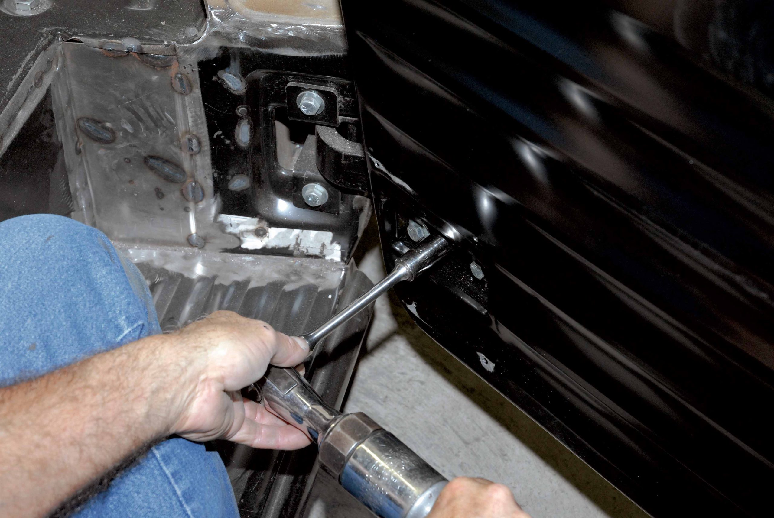
43 The A/C lines have to pass through the firewall, and that is done using bulkhead fittings. Here, one of the holes for the fittings is drilled with a step drill.
44 After the hole was drilled to size, the bulkhead fitting was inserted through the hole, and the nut was installed and tightened to secure the fitting to the firewall.
45 The other hole was drilled with a larger step drill bit because this hole is quite a bit larger than the other one.
46 After the hole was drilled to size, the larger fitting was installed in the firewall. Here, the large nut is tightened with a crescent wrench.
47 The evaporator was installed under the dash and was connected with the brackets supplied in the kit. It is important to run the heater and A/C lines before the evaporator is installed because when it’s in place, space is limited.
48 Looking under the unit, you can see the large firewall connection. The small hose is hidden behind the unit. All the wiring is color-coded, and many wires include plug-in connectors. Following the wiring diagram in the instructions will make the wiring easy to complete wire by wire and plug by plug.
49 The A/C controls are located in a plastic housing along with a pair of centrally mounted vents. Here, the housing is drilled for the mounting screws.
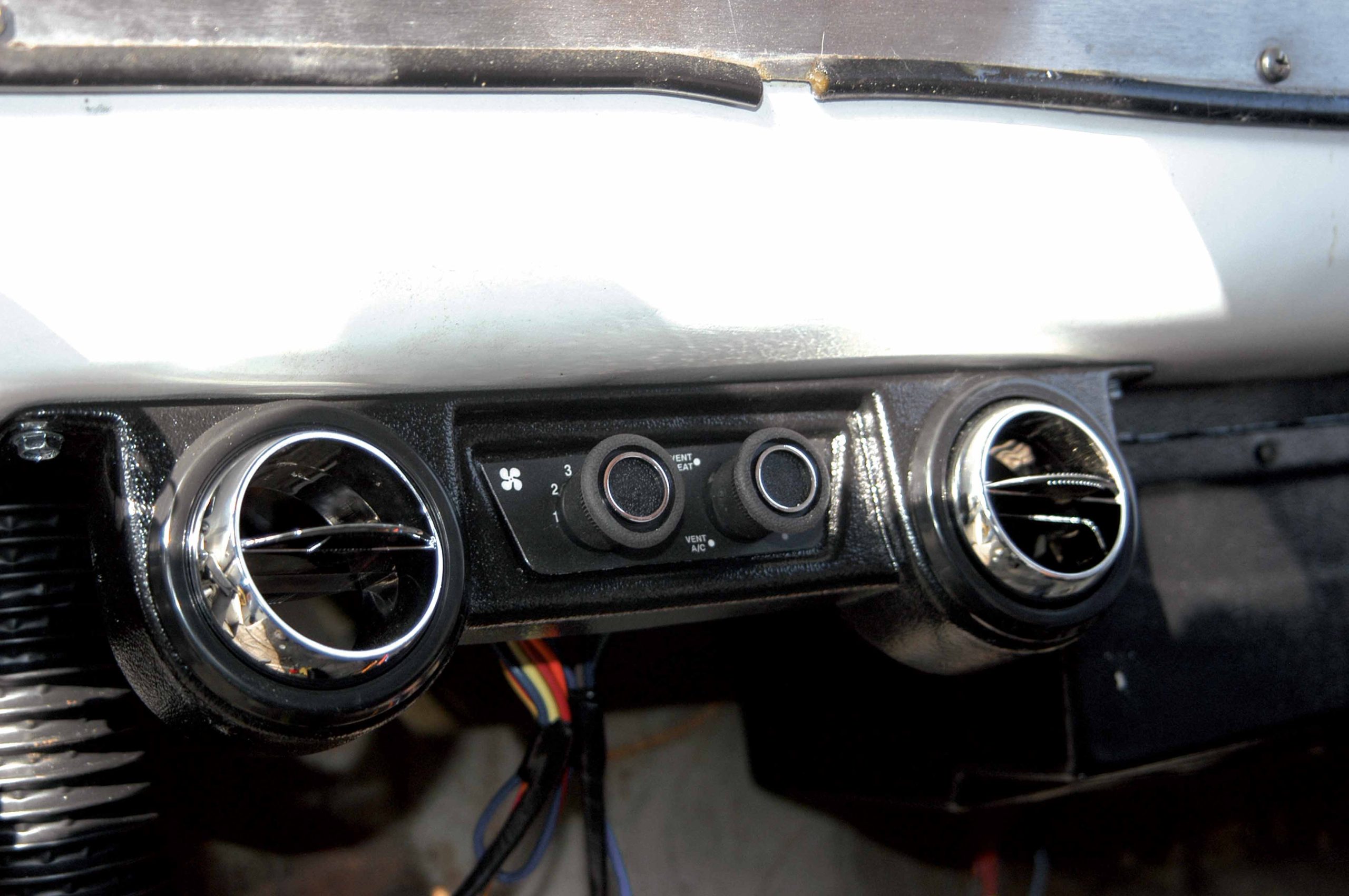
50 The control unit was installed under the center of the dash and was connected using a drill motor and self-tapping screws.
51 The control panel features the blower control knob and the selector knob for A/C and heat. Vents are located on both sides of the unit.
52 The evaporator features vacuum controls, which will be located under the dash. Each control is labeled and the wires and vacuum lines will be hooked up following the instructions.
53 The hose ends were connected to the bulkhead fittings in preparation for installing the hoses. The heater hoses also have to be routed through the firewall, and here the holes are drilled using a large step drill bit.
54 After the holes were drilled, large grommets were installed in the firewall as a safety precaution.
55 After the grommets were installed, they were coated with lubricant so that the radiator hoses can easily be routed through.
56 Both radiator hoses were routed through the grommets on the way to their intended engine fitting location.
57 One of the radiator-hose locations is in the aluminum manifold, as seen here. The fitting was covered with white Teflon tape to prevent leaks.
58 The other fitting was installed into the water pump, and here you can see that the bracket is built with a passage for the radiator hose.
59 The heater control valve has to be installed in the radiator-hose inlet line. Here, a good mounting position for the fitting is found.
60 After the mounting position was determined, the line was cut to size. It is important to make sure the heater control valve is installed in the correct direction.
61a-b Both of the heater hoses were lubricated to make the heater-control valve installation easier. After the hoses were connected, the clamps were tightened with a small nut driver. 62 The other end of the heater hose was run to the fitting on the manifold and the measurement was taken. Here, the thumb marks the spot where the hose will be cut. 63a-b After the hose was cut to length, it was connected to the fitting in the intake manifold. Here, the clamp is tightened with a nut driver. The other heater hose connects to the fitting on the water pump. Notice how the hose passes through the hole in the bracket. 64 There are two remaining air-conditioning lines that need to be made and installed. Here, a small hose is connected to the fitting on the bulkhead, while a measurement was made to the dryer. When the size was determined, the hose was cut accordingly. Note that the dryer had an inlet and an outlet side. Be sure to hook it up correctly.
65 After the hose was cut, it was connected to the fitting on the dryer. The measurement was perfect. 66 The hose was connected to the large fitting that is connected to the bulkhead fitting. The bulkhead fitting runs to the large fitting on the compressor. 67 When the length of the hose running to the compressor was determined, it was cut and connected to the fitting, as seen here. 68 Both of the hoses were removed and were installed in the crimping machine to finish them off. 69 After the hoses were completed, the small hose was connected to the dryer and the large hose was connected to the compressor. 70 It is important to tighten the hoses to prevent leaks. Here, the small hose that runs to the dryer is tightened with an open-end wrench. 71 The other hose runs from the bulkhead to the compressor and it was tightened with a large crescent wrench. 72 The climate-control panel and vents were connected to the center of the dash, but there are two additional vents that should be mounted to the ends of the dash. Here is one of the vents being drilled before installing it to the dash. 73 Using a drill motor and self-tapping screws, the vent was attached to the bottom of the dash. After the vents are installed, the air tubes can be connected from the evaporator to the vents. This completes the mounting of the air conditioning, and all that remains now is hooking up the wiring. You can do that to fit your application.


