
Edit Template
THE AUTO BUILDER
Menu
Featured

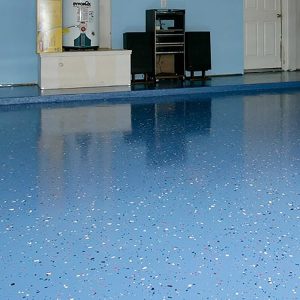
PRODUCT SPOTLIGHT: UCoat-It’s UCoat with UFlek-AF
It’s time to bring your garage floor from zero to hero with the UCoat with UFlek-AF System. If you’re like me, you know that a well-done garage floor is more than just eye candy—it’s a badge of honor. Here’s why UCoat with UFlek-AF should be your go-to.

SHOP PROJECT
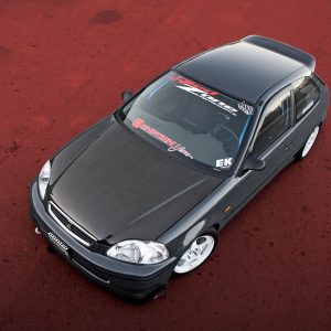
When you attend a Mustang & Shelby event, especially one the magnitude of the Rocky Mountain Mustang Roundup in Steamboat Springs, Colorado, it can become kind of a mind-boggling process to pick a “favorite” Mustang among the more than 750 entries. Nonetheless, it’s an assignment we relish. And at the 2006 RMMR, there were plenty of outstanding Mustangs and Shelbys to choose from.

STOPPING BEYOND DOUBT
NASCAR. It’s the most popular televised form of racing, with millions of fans across the nation. In fact, some believe NASCAR’s Cup Series Racing is the most popular sport in America. For all the money expended in Formula 1 (something in the neighborhood of $300 million a year for each of the top teams), it doesn’t approach the excitement, immensity or competitiveness found in this most American of sports.


Spotlighter
POPULAR READS
-
Product Spotlight: Bill Mitchell Products Aluminum LS Engine Block
-
PRODUCT SPOTLIGHT: 60-66 Chevy C10 Fresh Air Vent Block Off Plate
-
Product Spotlight: Pyramid Optimized Design Sequential Aurora Taillight for 1964½–1966 Mustang
-
PRODUCT SPOTLIGHT: Cam Covers for GEN/3 Coyote from Pyramid Optimized Design
CIMTEX RODS SUPER CAMEO: PART 4
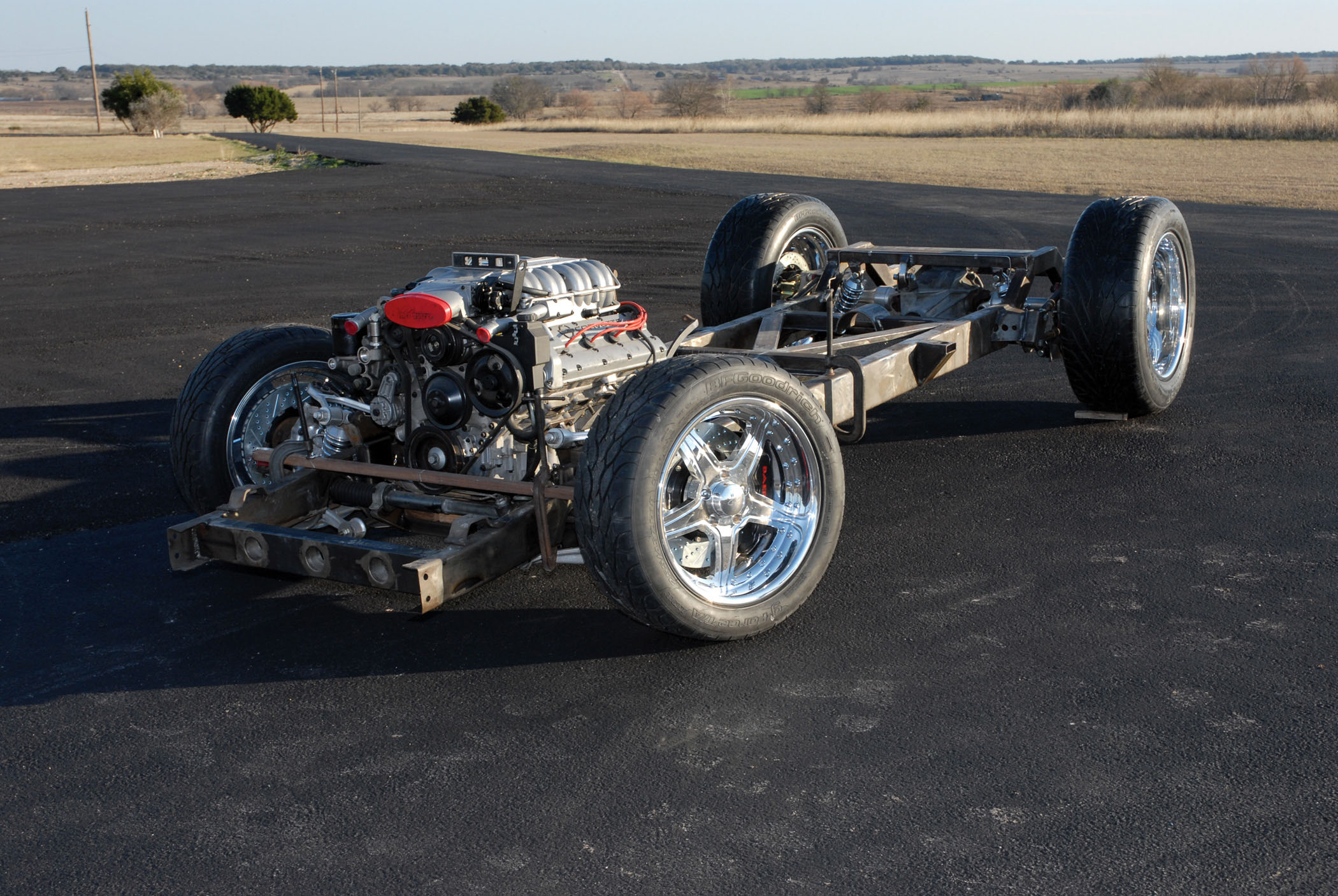
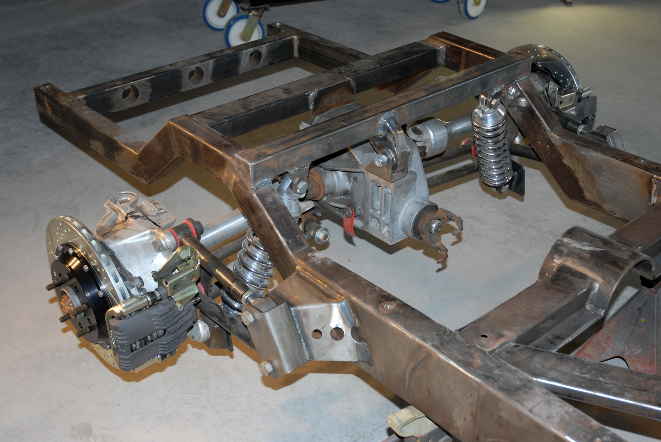
The Assembly of Our Braking System
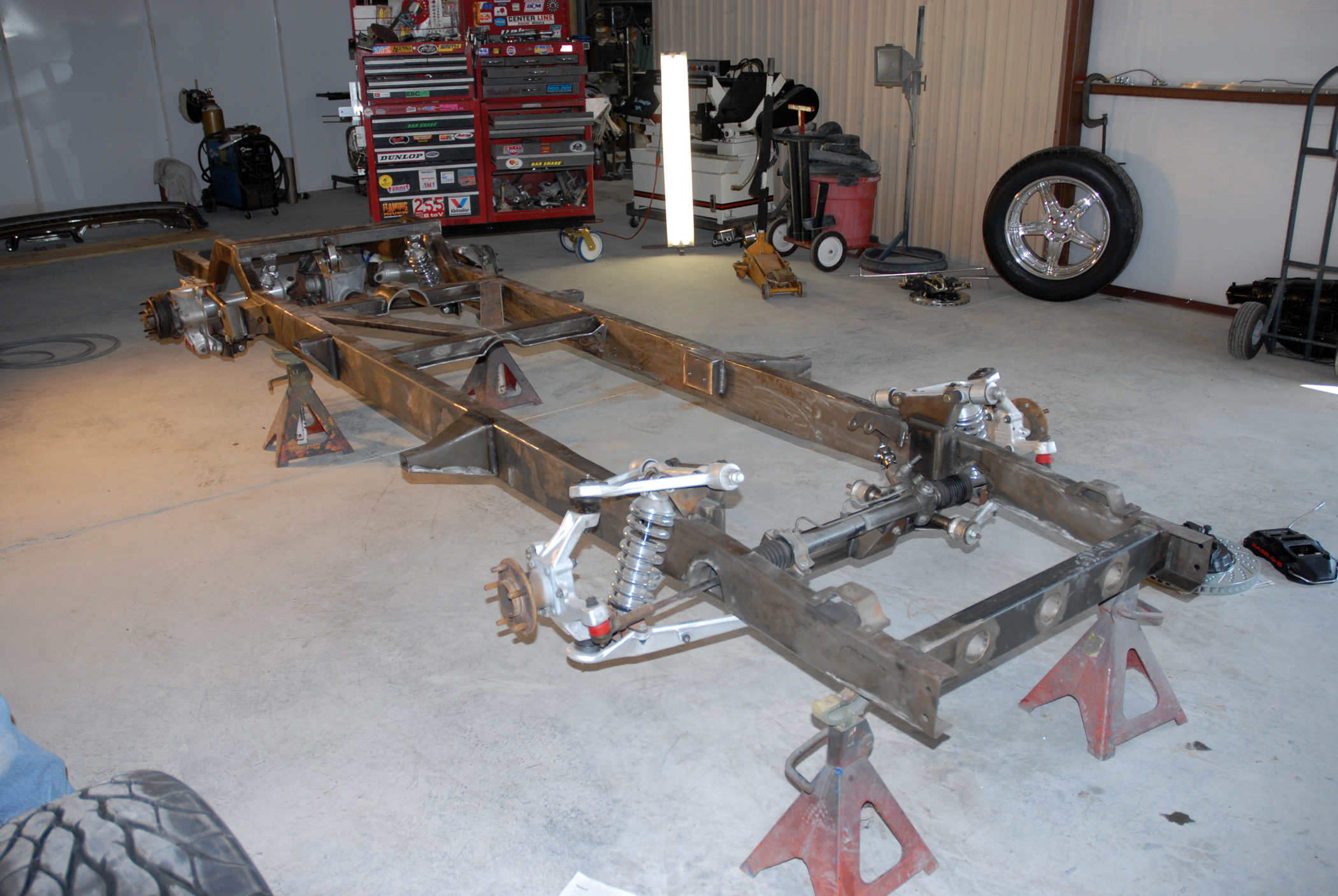
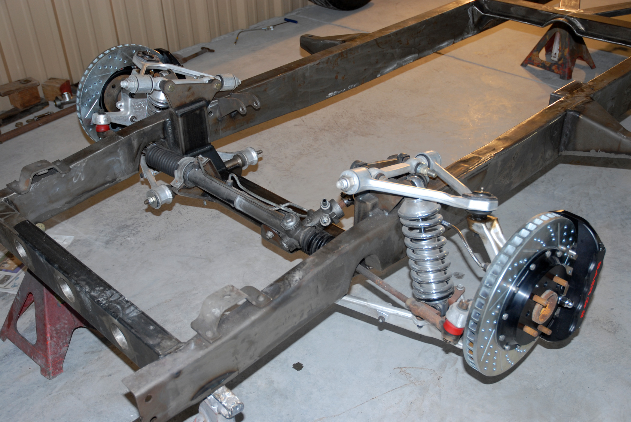
In parts two and three of The Auto Builder’s Cimtex Super Cameo series, we followed along as Cimtex Rods primaries Tim and Darrell Cimbanin installed one of Flat Out Engineering’s Corvette C4/C5 front and rear independent suspension crossmember kits beneath a 1956 Chevrolet 1/2-ton pickup chassis.
Of course, this was followed by the actual installation of the 1984-1987 Corvette C4 rack-and-pinion-steering-equipped IFS and the bolting up of the 1984-1987 Corvette C4 IRS, which makes for a pretty nice-handling street truck.
Of course, this was followed by the actual installation of the 1984-1987 Corvette C4 rack-and-pinion-steering-equipped IFS and the bolting up of the 1984-1987 Corvette C4 IRS, which makes for a pretty nice-handling street truck.
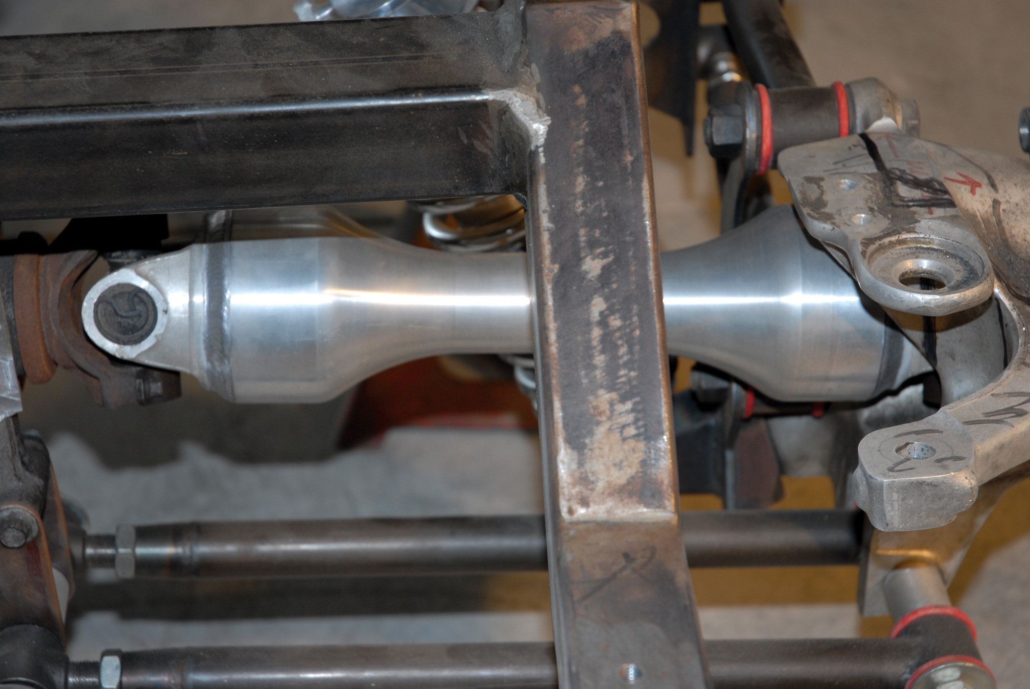
Along the way, some modifications to the Corvette C4 front suspension were made for the sake of simplicity and an enhanced ride. For openers, Flat Out Engineering designed its kit to incorporate a pair of 12-1/2-inch Aldan Eagle 659/450 coilover shock absorbers, which replace the somewhat antiquated GM designed Owens Corning Corvette C4 monoleaf fiberglass front spring.
Out back, Tim and Darrell Cimbanin also took the initiative to narrow the Vette IRS some 3 inches (1-1/2 inches per side) in order to accommodate the anticipated 305/50ZR20 (31-1/2-inch tall) BFGoodrich g-Force KDW Radial T/As, which is easier than having to perform any unsightly exterior sheetmetal modifications to the truck.
In the process, the Cimbanins also decided to eliminate that bulky aluminum Corvette C4 rear suspension trusswork, replacing it with a set of four heim-joint-equipped adjustable parallel control arms equipped with a set of red Energy Suspension polyurethane control arm bushings. With that done, the guys at Cimtex Rods also installed a pair of 12-1/2-inch-long Aldan Eagle 654/400 coilover rear shocks.
In the process, the Cimbanins also decided to eliminate that bulky aluminum Corvette C4 rear suspension trusswork, replacing it with a set of four heim-joint-equipped adjustable parallel control arms equipped with a set of red Energy Suspension polyurethane control arm bushings. With that done, the guys at Cimtex Rods also installed a pair of 12-1/2-inch-long Aldan Eagle 654/400 coilover rear shocks.
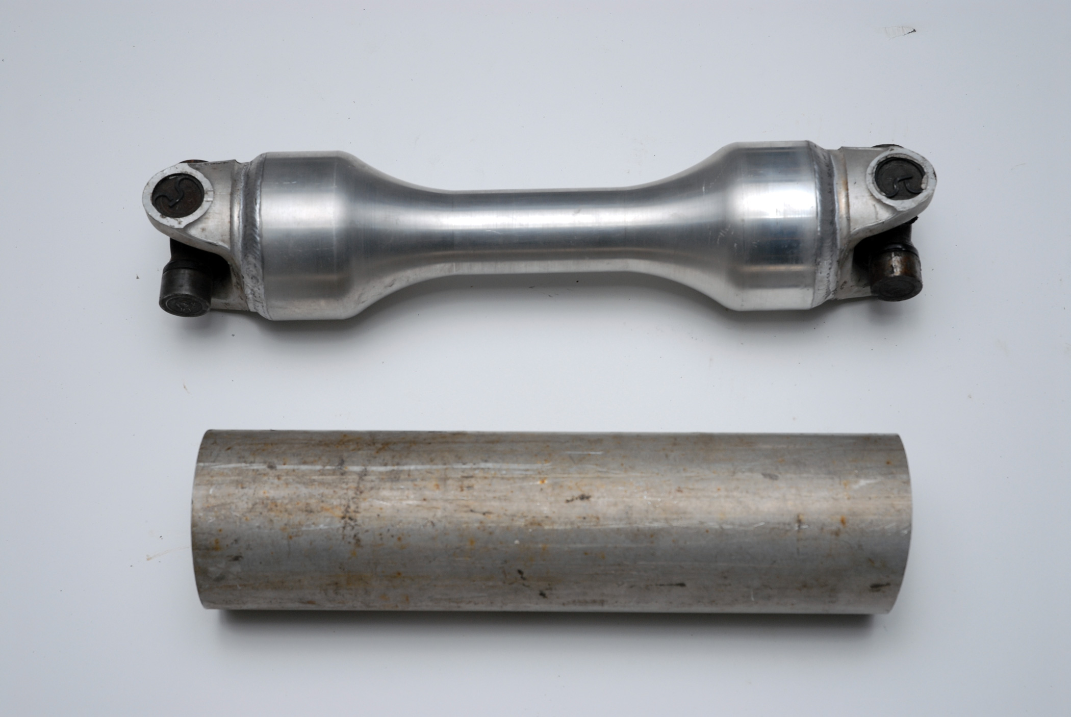
There was one other major modification to the rear suspension, which we were not able to cover in the short time we spent at Cimtex Rods last summer photographing part three. That was the fabrication of a pair of CNC 6061 billet aluminum “wishbone” half shafts, which Darrell machined up to replace those clunky-looking modified factory units. These half shafts make use of the OE Corvette universal joints, which have been welded to each end of the new CNC half shafts, and they really look great! Ultimately they will be show polished when Cimtex Rods’ Super Cameo is completed.
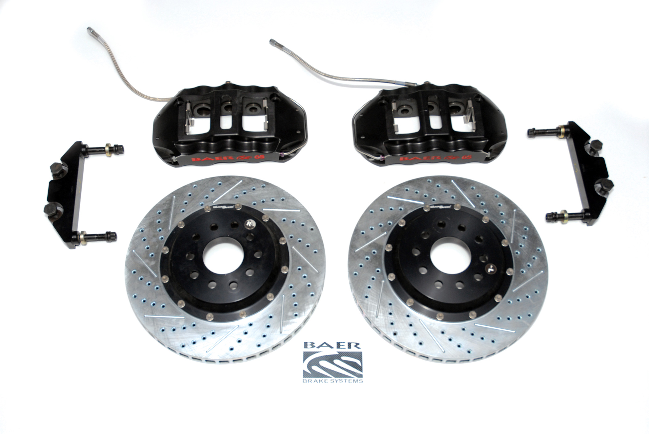
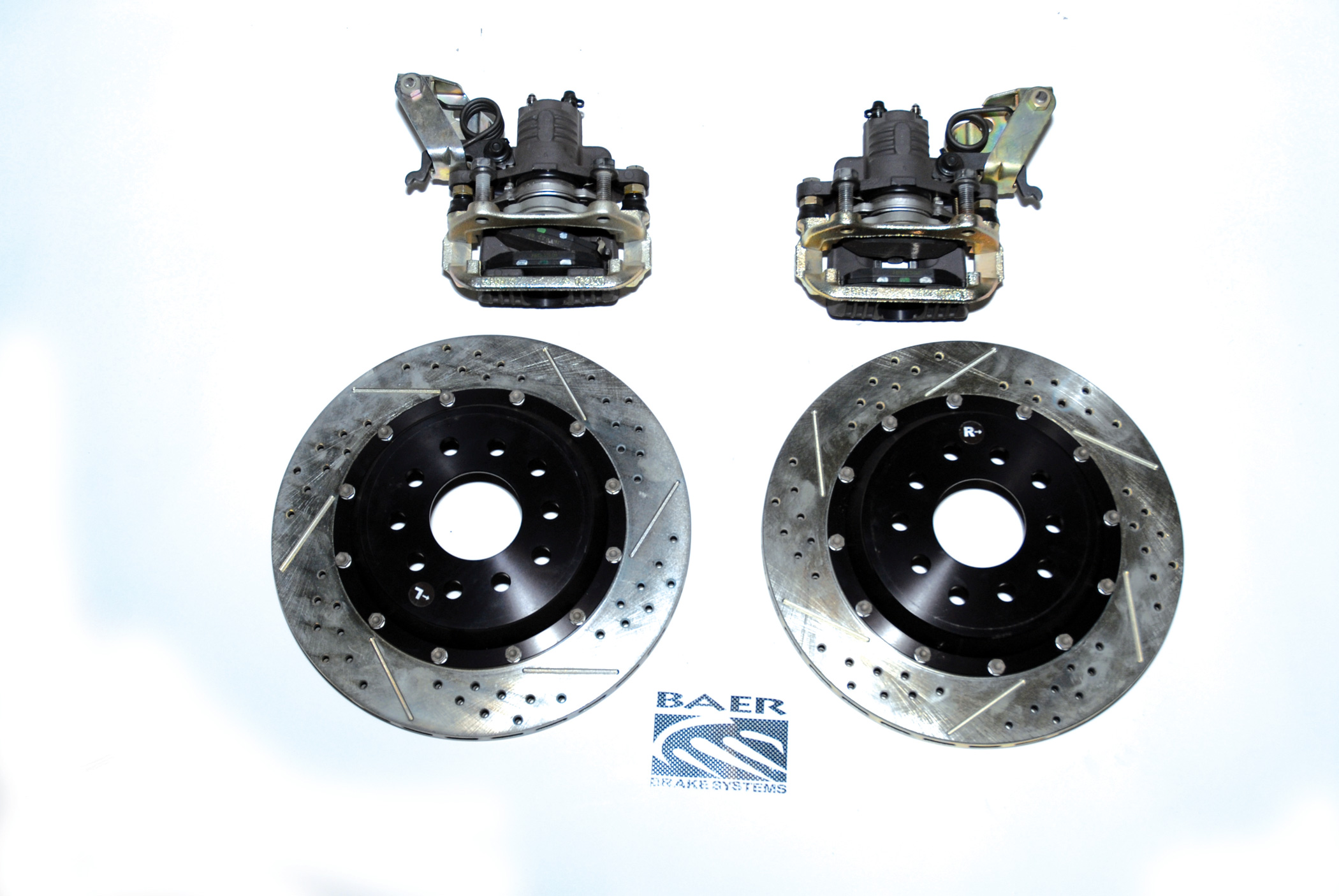
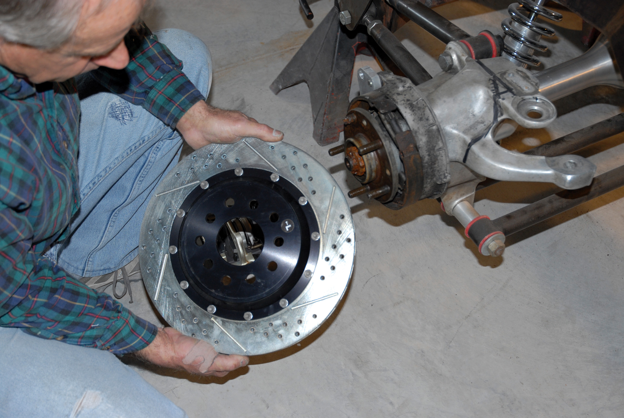
In this segment of our Cimtex Super Cameo buildup series we will be covering the assembly of our braking system, which includes the installation of a pair of 15-inch, cross-drilled and vented front disc brake rotors and Baer Brake System’s new “Extreme Plus” six-piston billet aluminum, sintered metallic-pad-equipped front calipers (part No. 4301014,) along with Baer’s “DecelaRotors” ’84-’87 C4 Corvette single-piston, 12-inch rear brake caliper (part No. 5556-020) with an emergency brake lever feature.
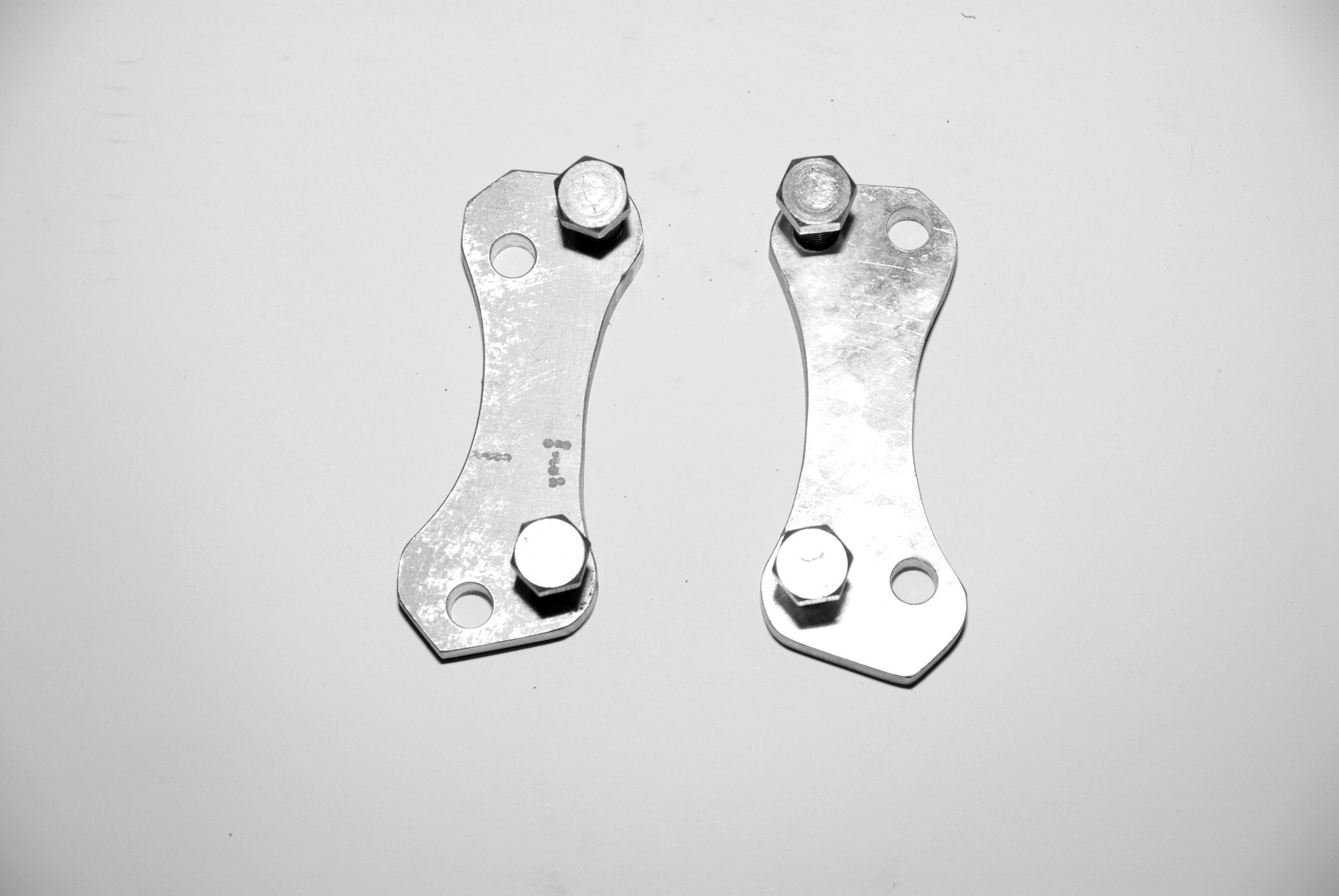
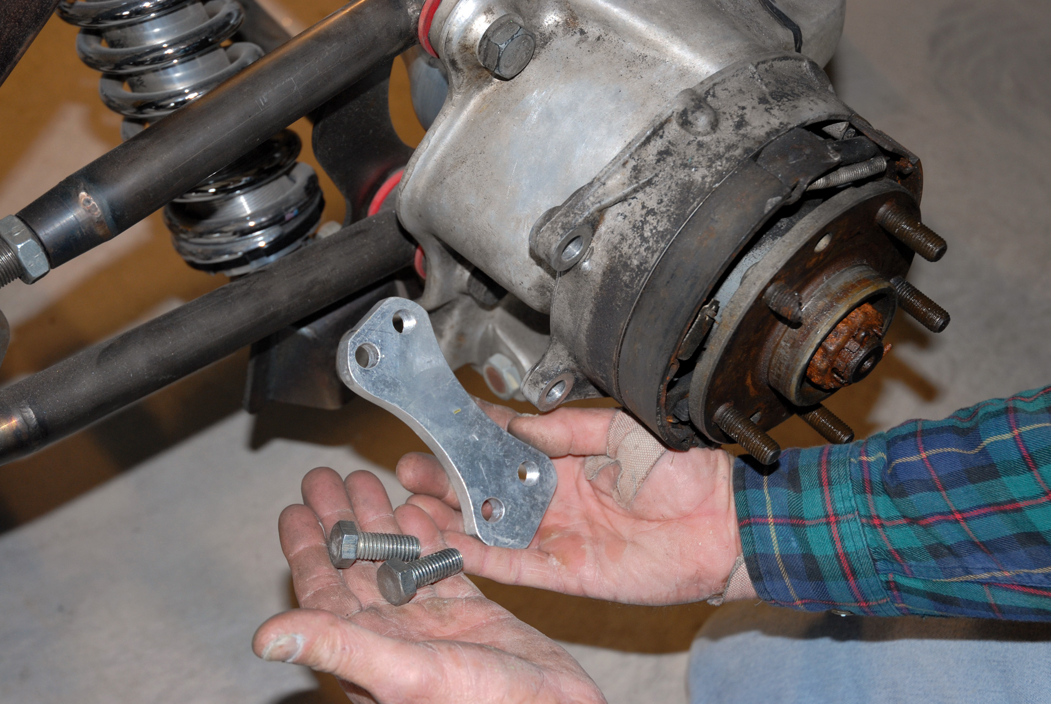
Once again some modifications to the basic rear brake system were made, albeit for the sake of looks rather than performance. Trial fitting the rear system revealed that the OE-size, 12-inch Corvette vented rear rotors were sort of lost inside those massive 20×10-inch Intro two-piece modular rear wheels. After conferring with Baer’s VP of Marketing Todd Gartshore, a pair of the company’s 13-1/2-inch cross-drilled and slotted rotors was substituted. However, in order to accomplish this, it was necessary to fabricate a pair of 1/2×3-1/2×2-inch billet aluminum “dog bone” disc brake caliper extension brackets. They use a pair of 1/2-inch bolts to secure the single-piston Vette calipers in place.
Once again some modifications to the basic rear brake system were made, albeit for the sake of looks rather than performance. Trial fitting the rear system revealed that the OE-size, 12-inch Corvette vented rear rotors were sort of lost inside those massive 20×10-inch Intro two-piece modular rear wheels. After conferring with Baer’s VP of Marketing Todd Gartshore, a pair of the company’s 13-1/2-inch cross-drilled and slotted rotors was substituted. However, in order to accomplish this, it was necessary to fabricate a pair of 1/2×3-1/2×2-inch billet aluminum “dog bone” disc brake caliper extension brackets. They use a pair of 1/2-inch bolts to secure the single-piston Vette calipers in place.
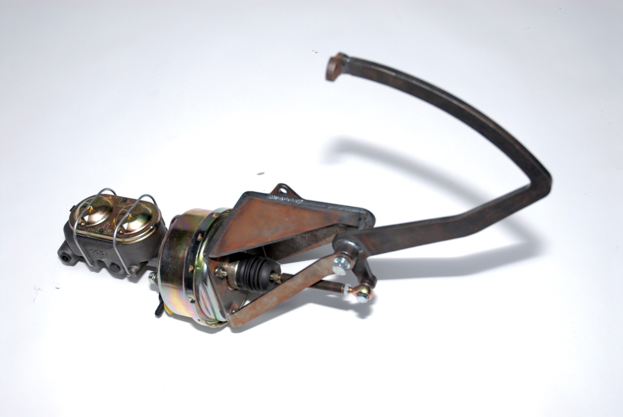
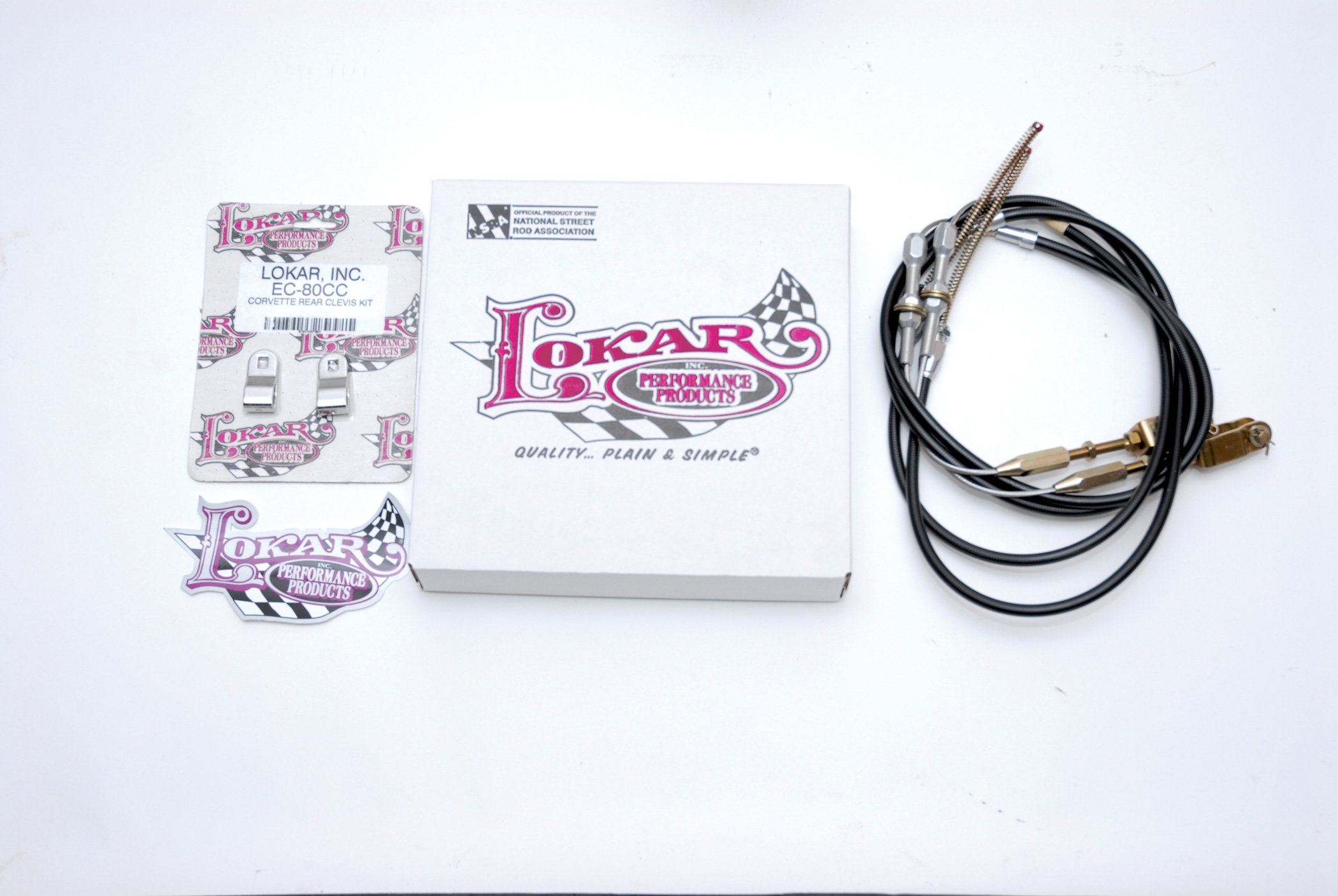
With that done, the next order of business was the installation of one of Lokar Performance Products’ Corvette emergency brake cable kits (part No. EC-8004U), along with one of its Corvette rear clevis kits (part No. EC-80CC). This was followed with the selection of a brake pedal booster assembly. After a quick call to Total Cost Involved’s Andy Brosche, the guys ordered up a complete pedal assembly (part No. 633-6510-000). This assembly includes the brake pedal extension and swinging brake pedal bracket, the master cylinder and power booster and the brake reservoir. Arriving at the proper location to mount the unit to the chassis required bolting up the cab to the body mounts on the chassis. Once the correct location was achieved, a 1/4x6x4-inch mounting platform, or pad, was fabricated out of sheet stock and welded to the ’56’s boxed-in framerails. This pad was then drilled and tapped to accommodate the 9/16-inch mounting bolts, and the pedal assembly was on for keeps.
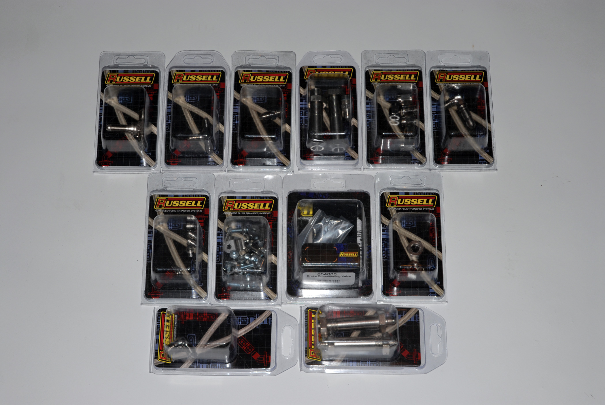
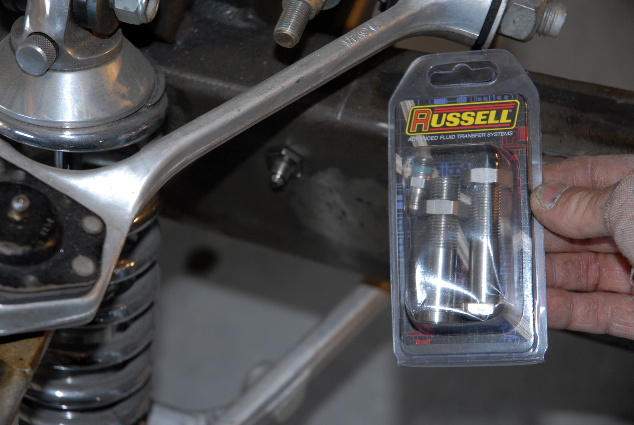
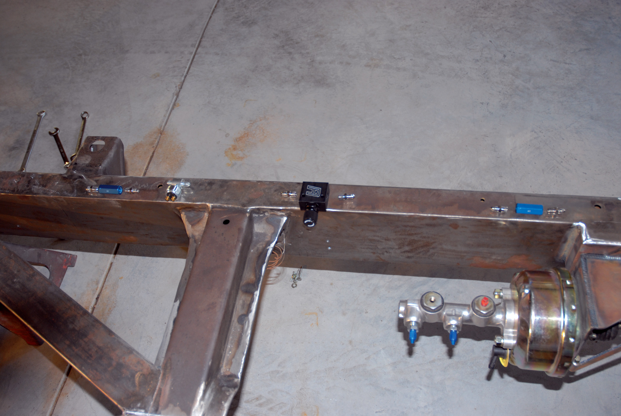
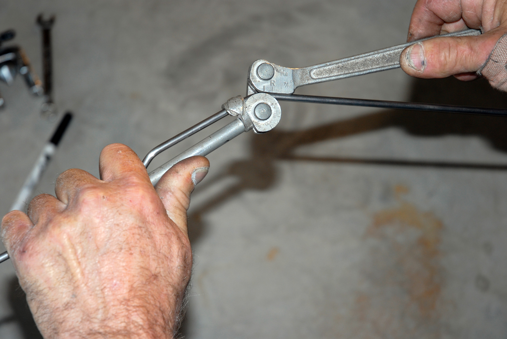
The next order of business was bending up the Cameo’s stainless steel brake lines. First a call was placed to Russell Performance Products, a division of the Edelbrock Corporation, and a whole slew of 3/16-inch AN-3 stainless steel “T” and line junction fittings was ordered, along with one of Russell Performance’s disc brake proportioning valves. These fittings were simultaneously bent up using the 3/16-inch stainless steel brake line material, which was obtained from San Antonio’s Gordon Chisenhall Specialties, to fashion the entire stainless steel brake line system. These brake lines were subsequently held in place using Russell Performance’s countersunk 8/32-inch Allen head brake line clamps, and the fit and finish is absolutely great.
Of course, the final touch was the installation of a set of 18×8-inch front (with a 4-1/2-inch backspace) and 20×10-inch rear (with a 5-inch backspace) Intro Rockman chrome-plated, two-piece, billet aluminum rivet wheels, rolling on a set of P255/45ZR18 BFGoodrich g-Force KDW T/As up front and P305/50ZR20 BFGoodrich KDW T/A radials on the rear.
So there you have it: In just four easy installments, the chassis on Cimtex Rods’ Super Cameo project truck is complete and sitting on four tires and wheels. In our next installment we will cover the buildup of our Jimmy G./racetrans.com GM 4L80E transmission, which will back up our Corvette ZR1 engine, as well as cover the programming of our Compu-Shift electronic transmission controller. Then, too, we’ll show how the engine and transmission mounts were fabricated, so stay tuned!
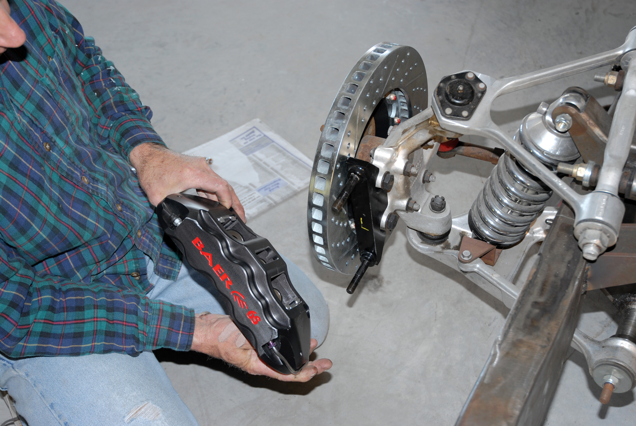
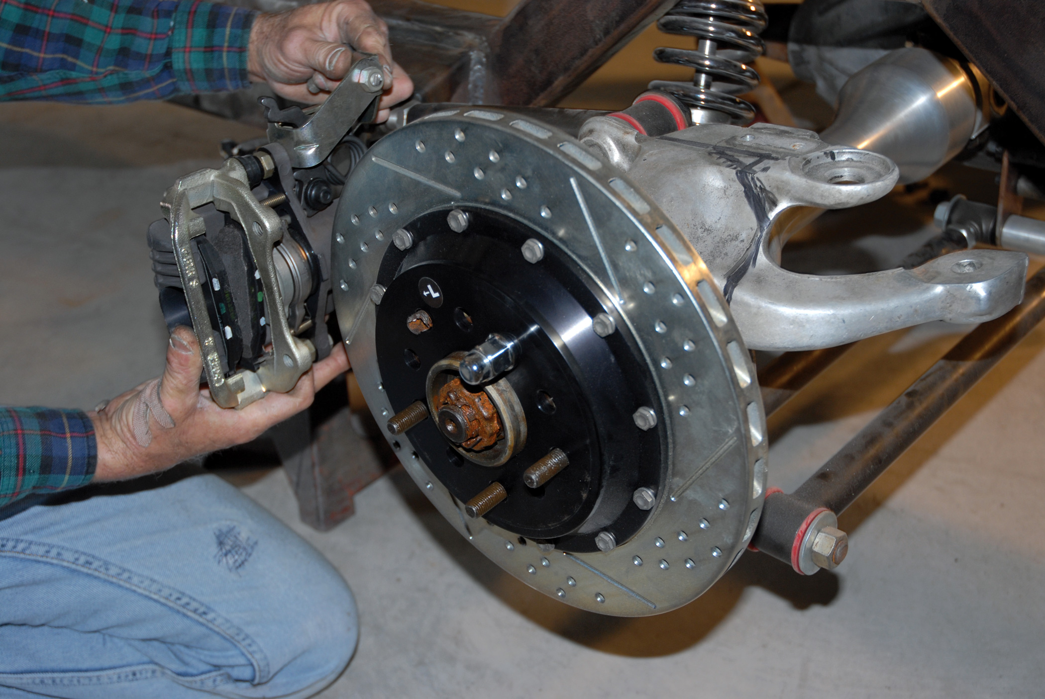
1. Shown is Baer Brake Systems’ Extreme Plus front braking system upgrade for the C4/C5 Corvette (part No. 4301014). This setup features everything you see here.
2. Also selected was Baer Braking Systems’ 1984-1987 Corvette C4 DecelaRotors rear disc brake setup, which features a cross-drilled and slotted 12-inch hat rotor and single-piston Corvette C4-type caliper (part No. 5556-020).
3. In order to accomplish this feat, Darrell fabricated a “dog bone” adapter bracket machined out of 1/2x3-1/2x2-inch-thick 6061 billet aluminum flat stock.
4. Also enlisted in the build was a Total Cost Involved complete pedal assembly (part No. 633-6510-000), which included the brake pedal extension, the mounting bracket, a power brake booster and dual reservoir.
5. Also on board is a complete selection of Russell Performance 3/16-inch, stainless steel AN-3 line and T-fittings, as well as a Russell Performance disc brake proportioning valve, which will be incorporated into the brake system.
6-7. A throwback from our last installment was the late fabrication of a pair of 6061 CNC billet aluminum wishbone half shafts, which replaced the modified Corvette C4 units. These billet shafts have the OE Corvette U-joint housings welded to each end and use the OE Corvette U-joints. These pieces will be show polished at a later date.
6-7. A throwback from our last installment was the late fabrication of a pair of 6061 CNC billet aluminum wishbone half shafts, which replaced the modified Corvette C4 units. These billet shafts have the OE Corvette U-joint housings welded to each end and use the OE Corvette U-joints. These pieces will be show polished at a later date.
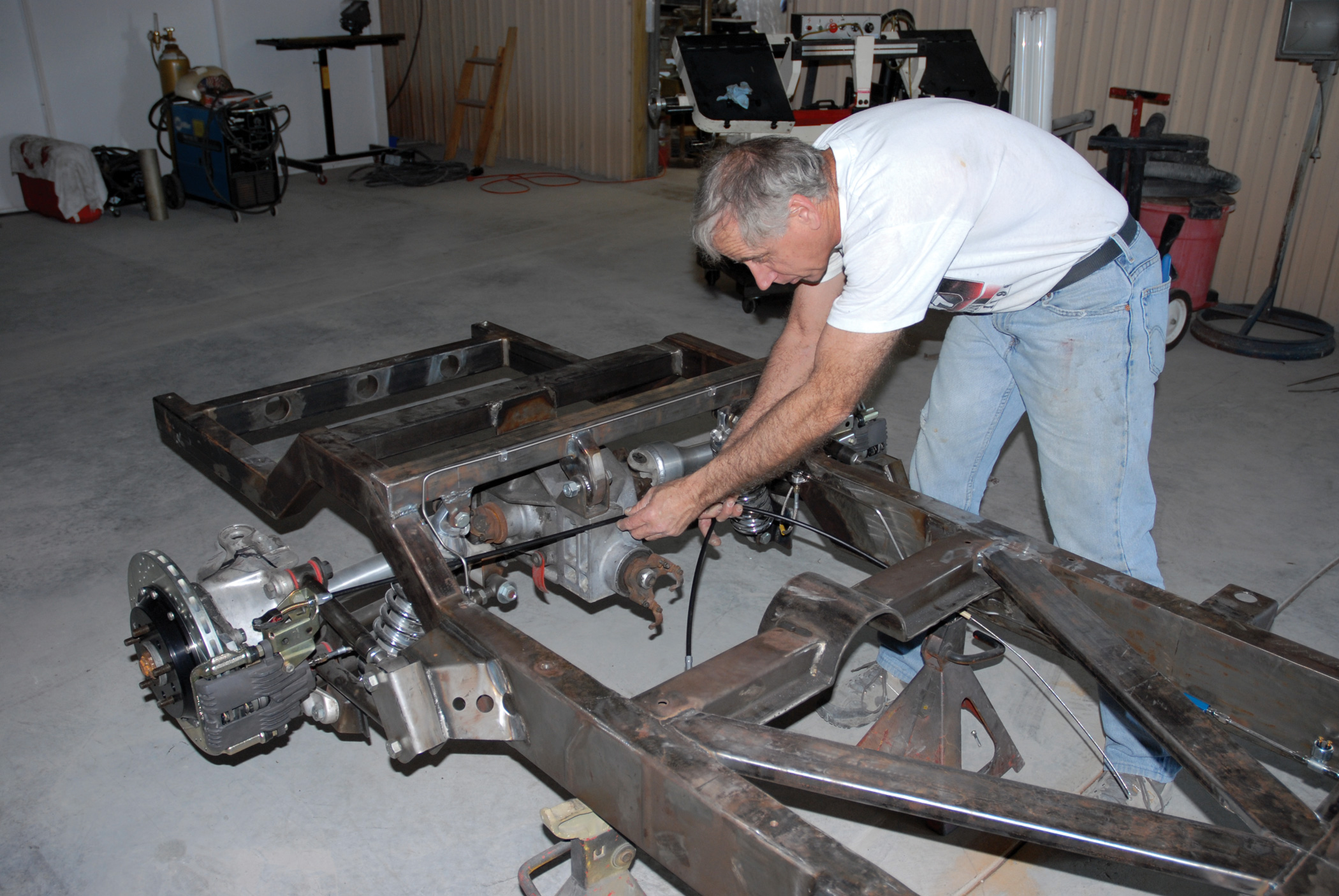
8. Now it’s time to install the brakes. With our highly modified ’56 Chevrolet chassis up on jackstands, the work begins.
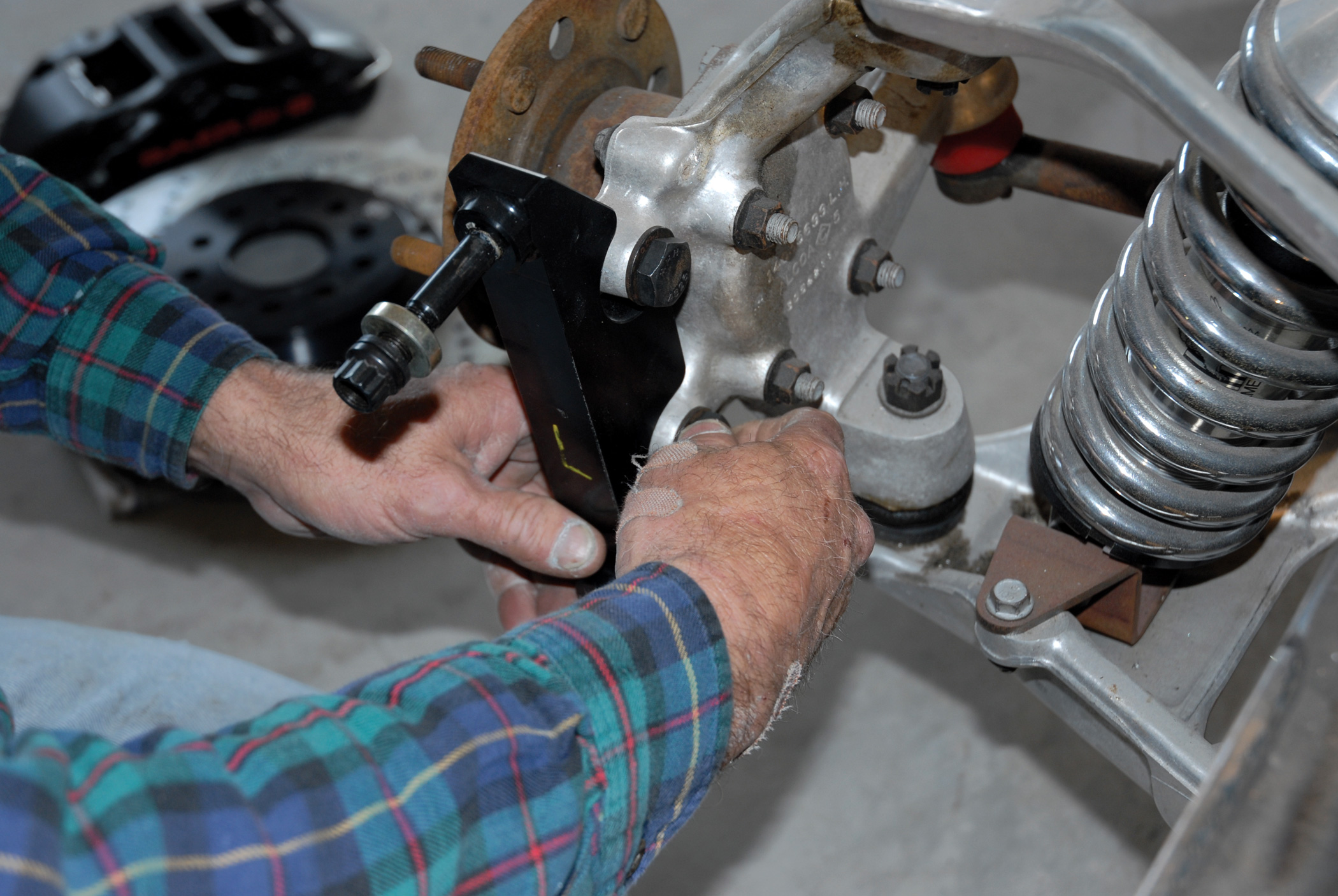
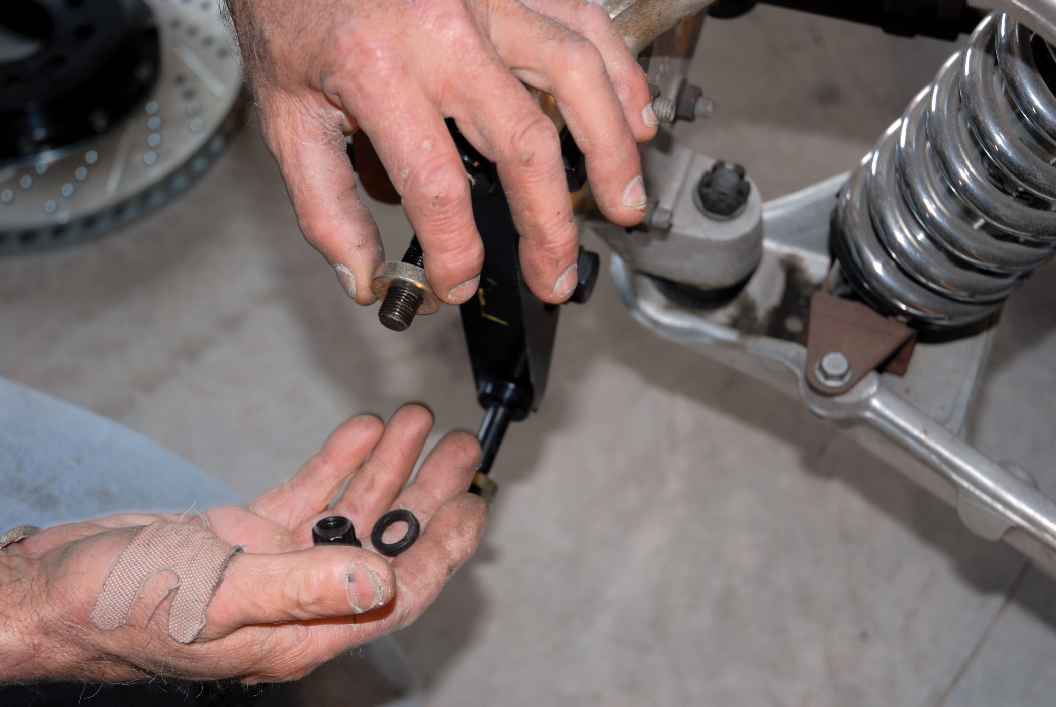
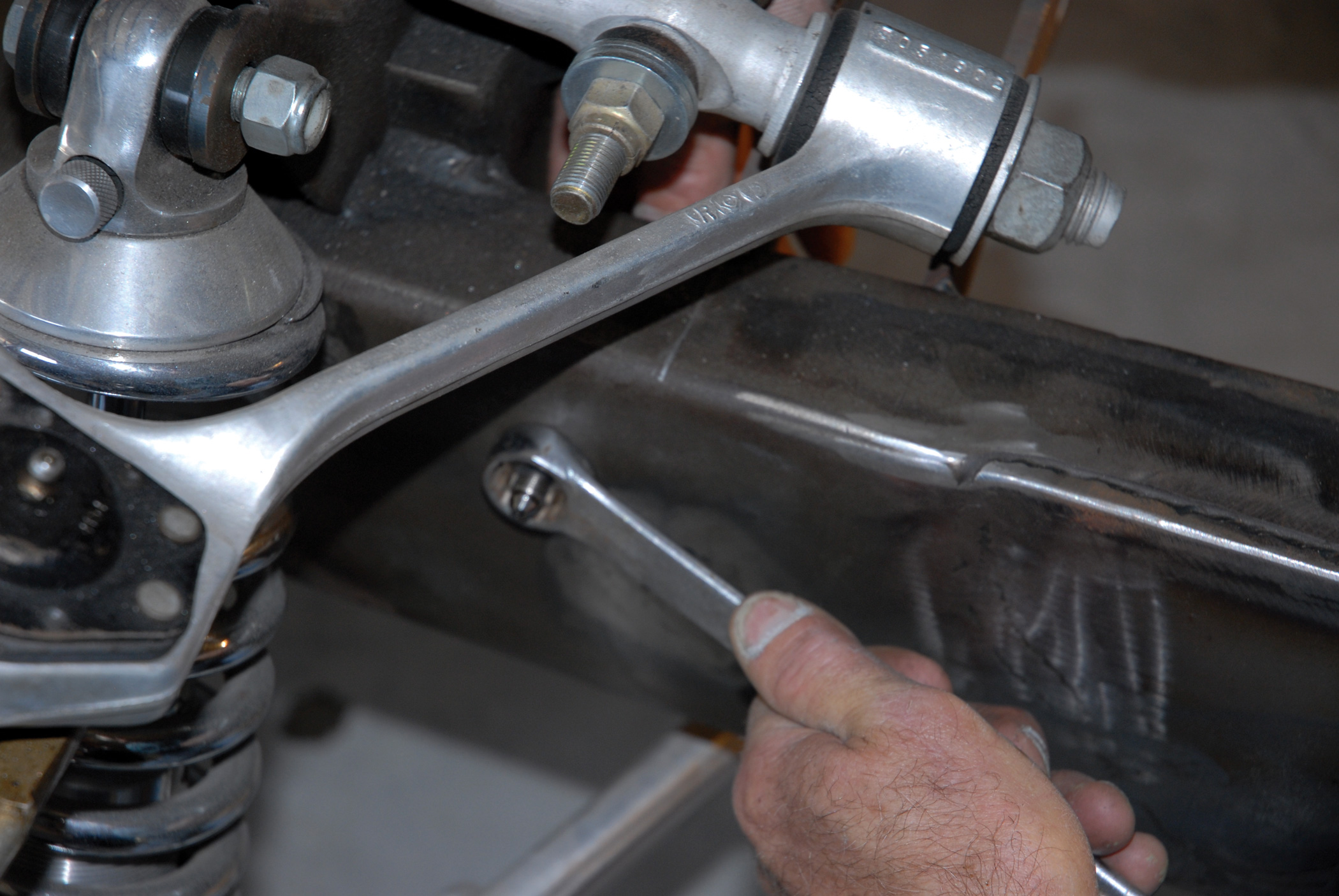
9. First Darrell installs Baer Braking Systems’ Extreme Plus driver’s-side disc brake caliper mounting bracket to the Corvette front hub assembly using the 1/2-inch bolts provided in the Baer kit. These will later be torqued to 70 ft-lb.
10. Shown are the 1/2-inch bolts and washers that come in the Baer Extreme Plus kit. Prior to final assembly, everything gets test fitted to avoid any problems.
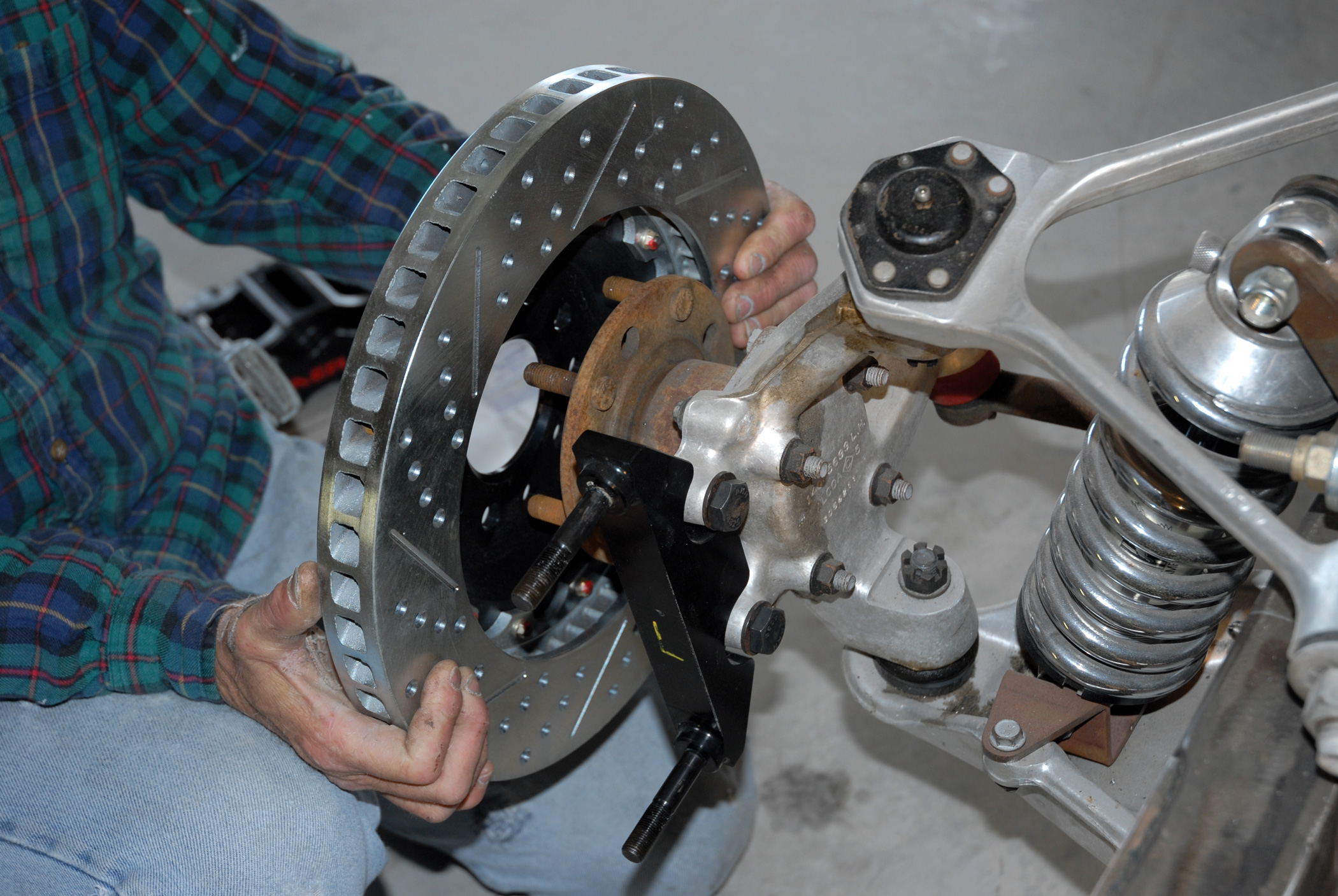
11. On goes the Baer Extreme Plus 15-inch cross-drilled and slotted hat rotor, which is held in place by a single lug nut.
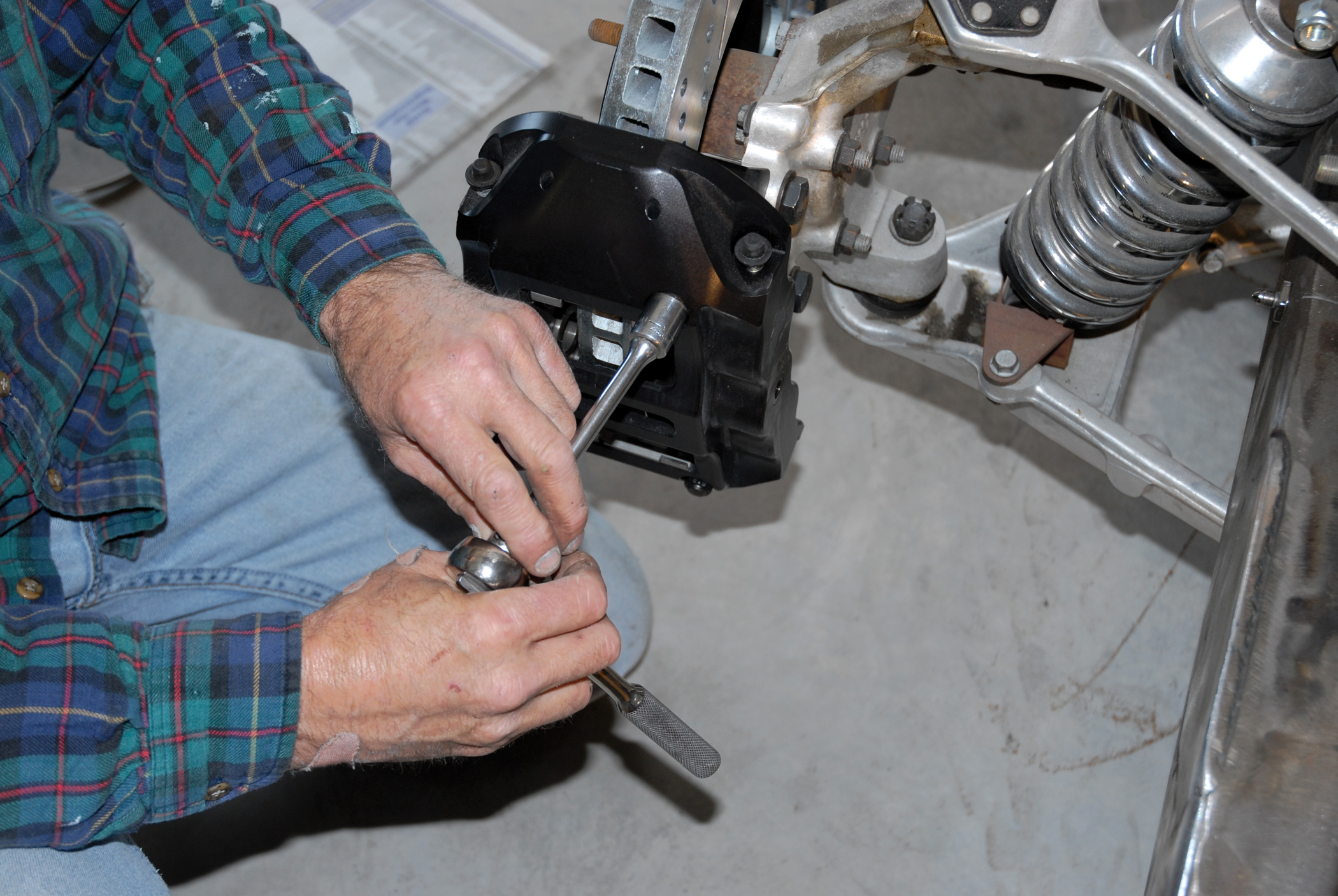
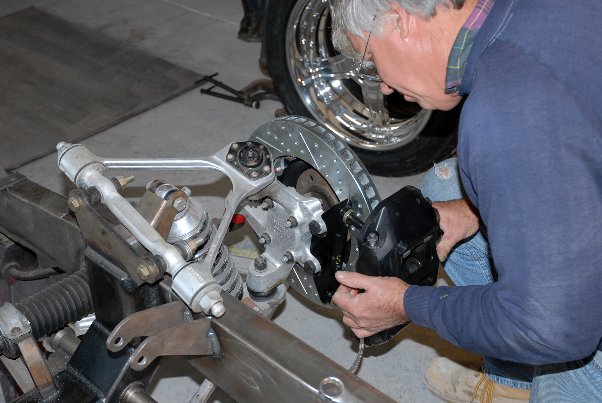
12-13. Of course, this is followed with the installation of the six-piston Baer Extreme Plus disc brake caliper with the 1/2-inch mounting bolts being final torqued to 70 ft-lb.
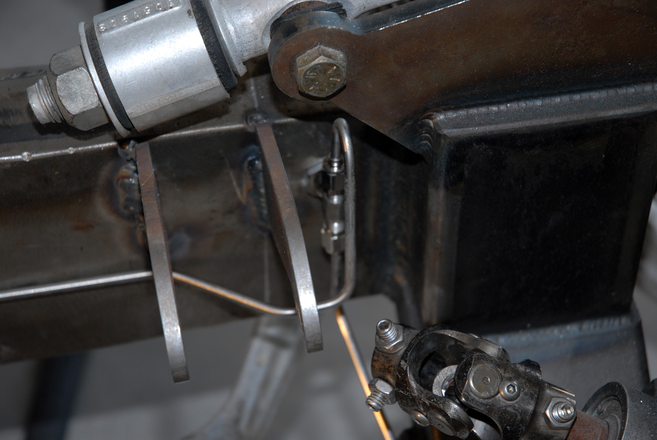
12-13. Of course, this is followed with the installation of the six-piston Baer Extreme Plus disc brake caliper with the 1/2-inch mounting bolts being final torqued to 70 ft-lb.
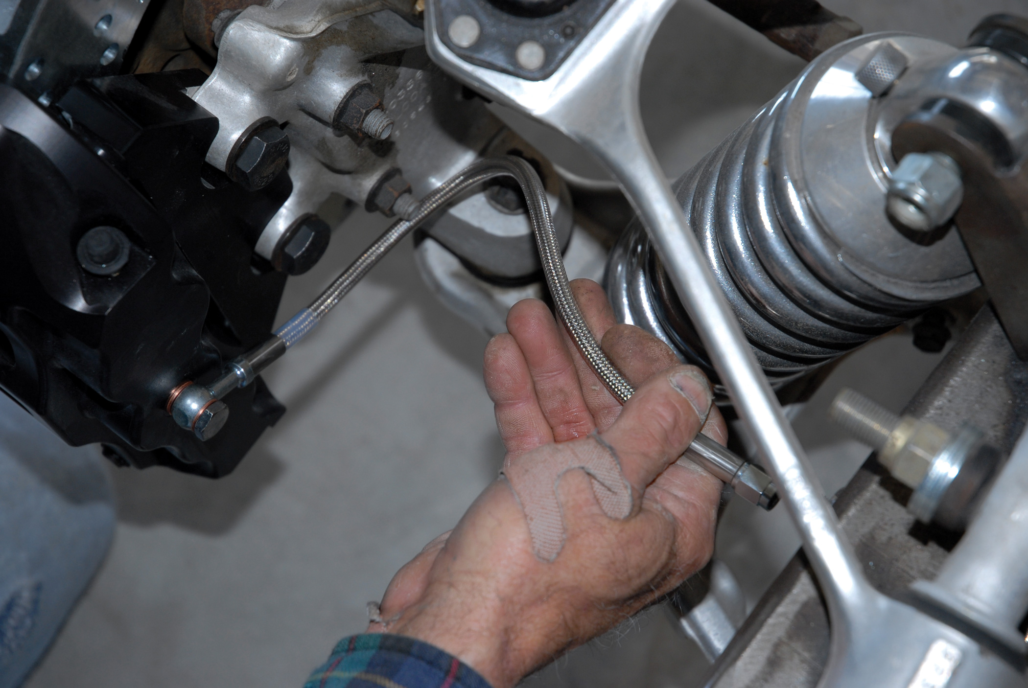
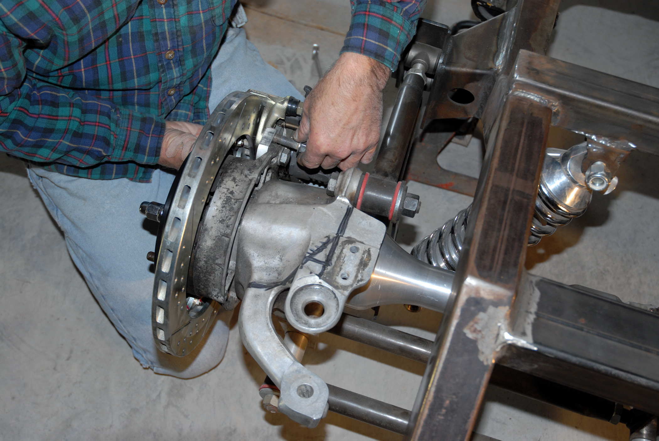
14. Next comes the installation of the provided 3/16-inch stainless steel brake line to the nipple fitting on the Baer Extreme Plus six-piston caliper.
15-17. This is followed by the drilling of a 1/2–inch hole dead center in the chassis to accommodate the 1/2x2-1/4-inch Russell Performance stainless steel brake line fitting, which will be part of the new brake line system.
15-17. This is followed by the drilling of a 1/2–inch hole dead center in the chassis to accommodate the 1/2x2-1/4-inch Russell Performance stainless steel brake line fitting, which will be part of the new brake line system.
15-17. This is followed by the drilling of a 1/2–inch hole dead center in the chassis to accommodate the 1/2x2-1/4-inch Russell Performance stainless steel brake line fitting, which will be part of the new brake line system.
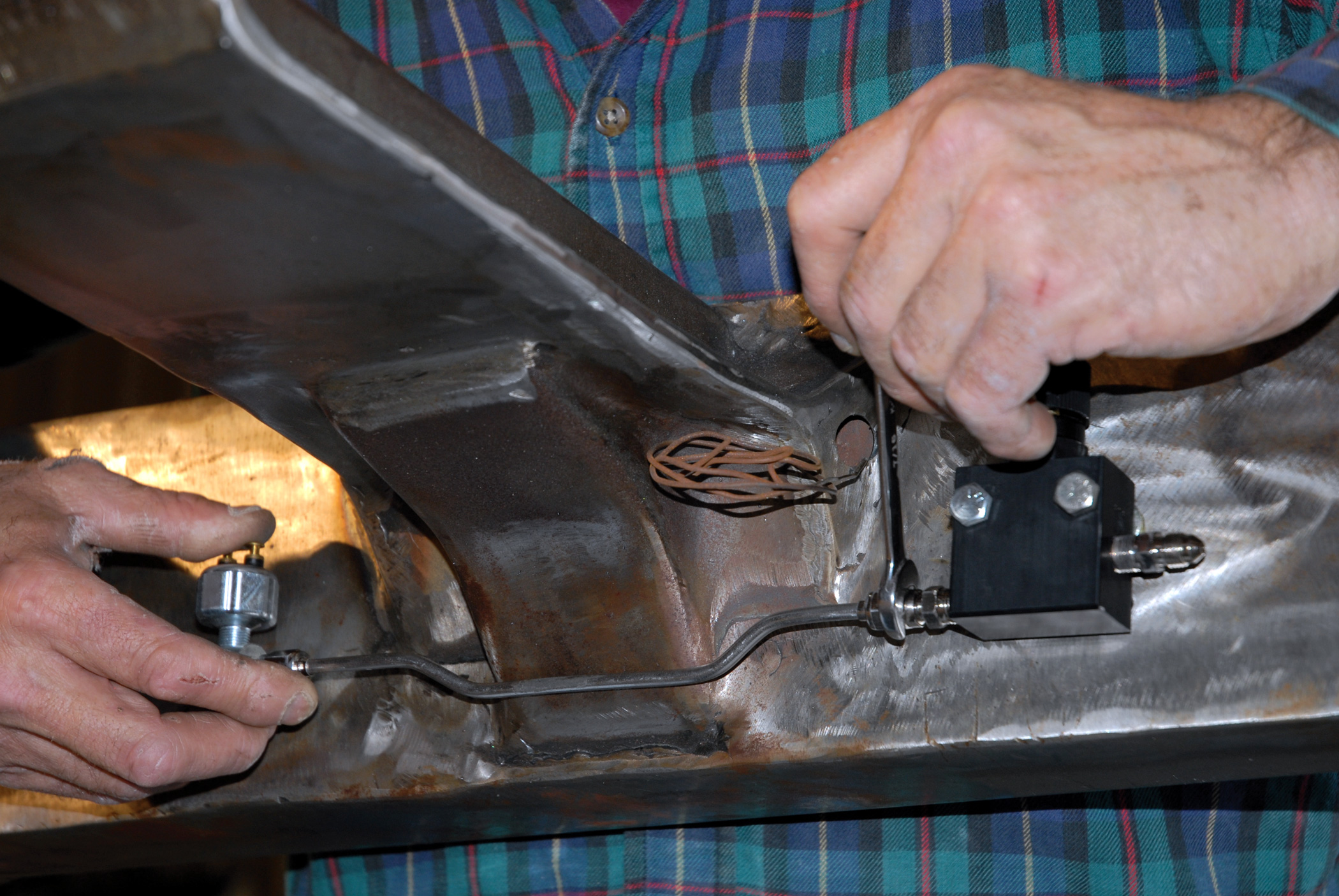
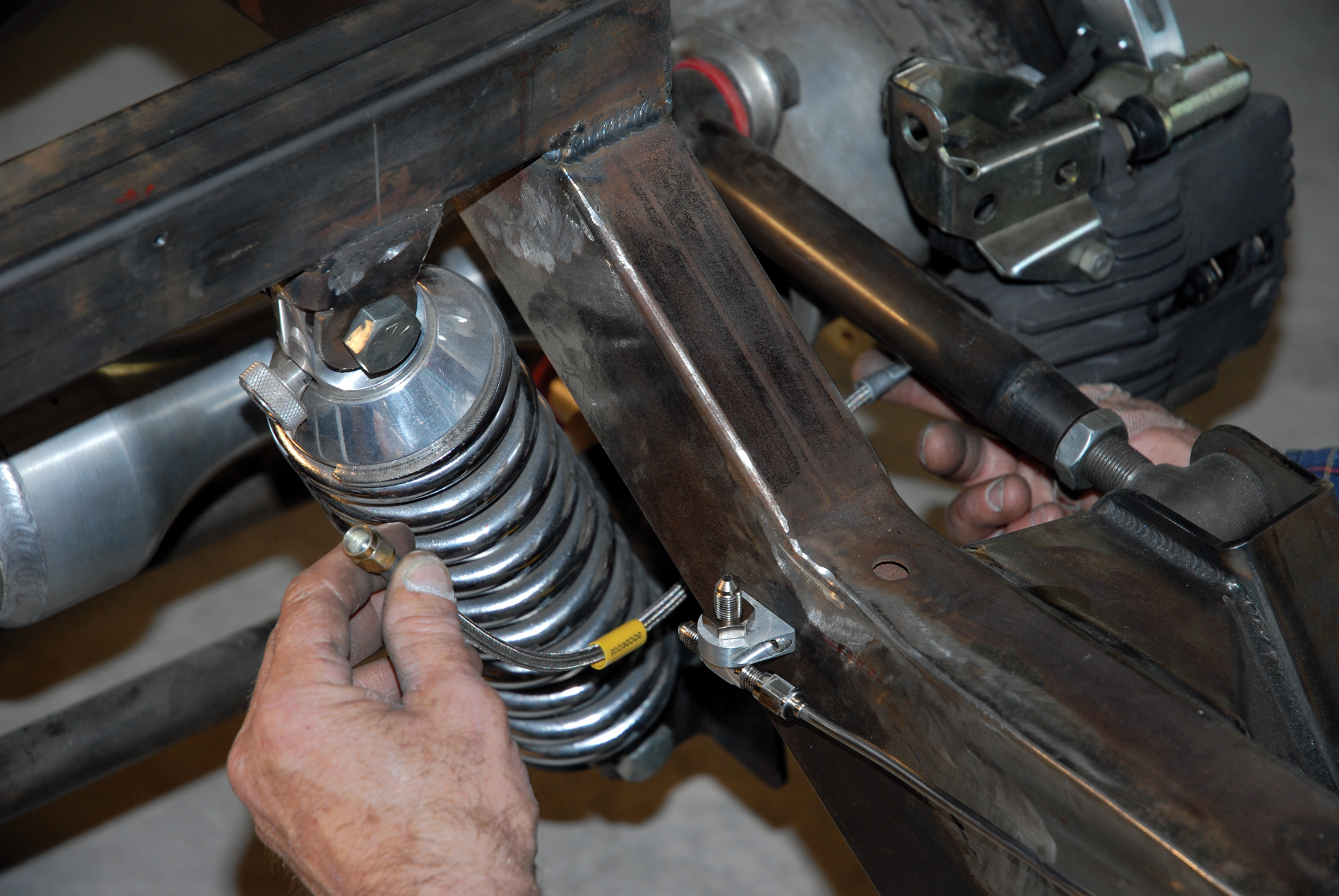
18. With that done, a special stainless steel T-fitting is attached to the opposite side, which will intersect with the front and rear brake lines.
19. Over on the passenger’s side of the chassis, Tim Cimbanin repeats the same brake installation process.
20. Here you have it: the completed Extreme Plus front disc brake system.
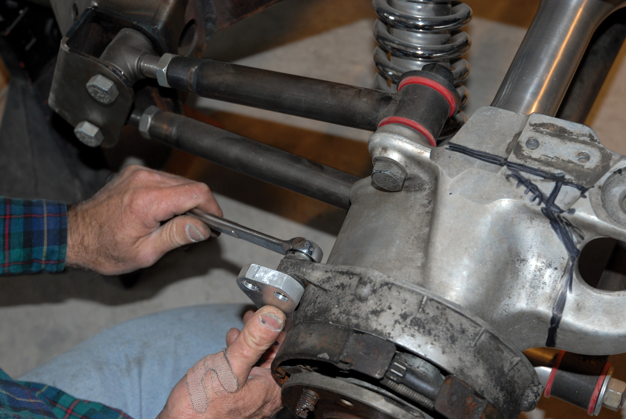
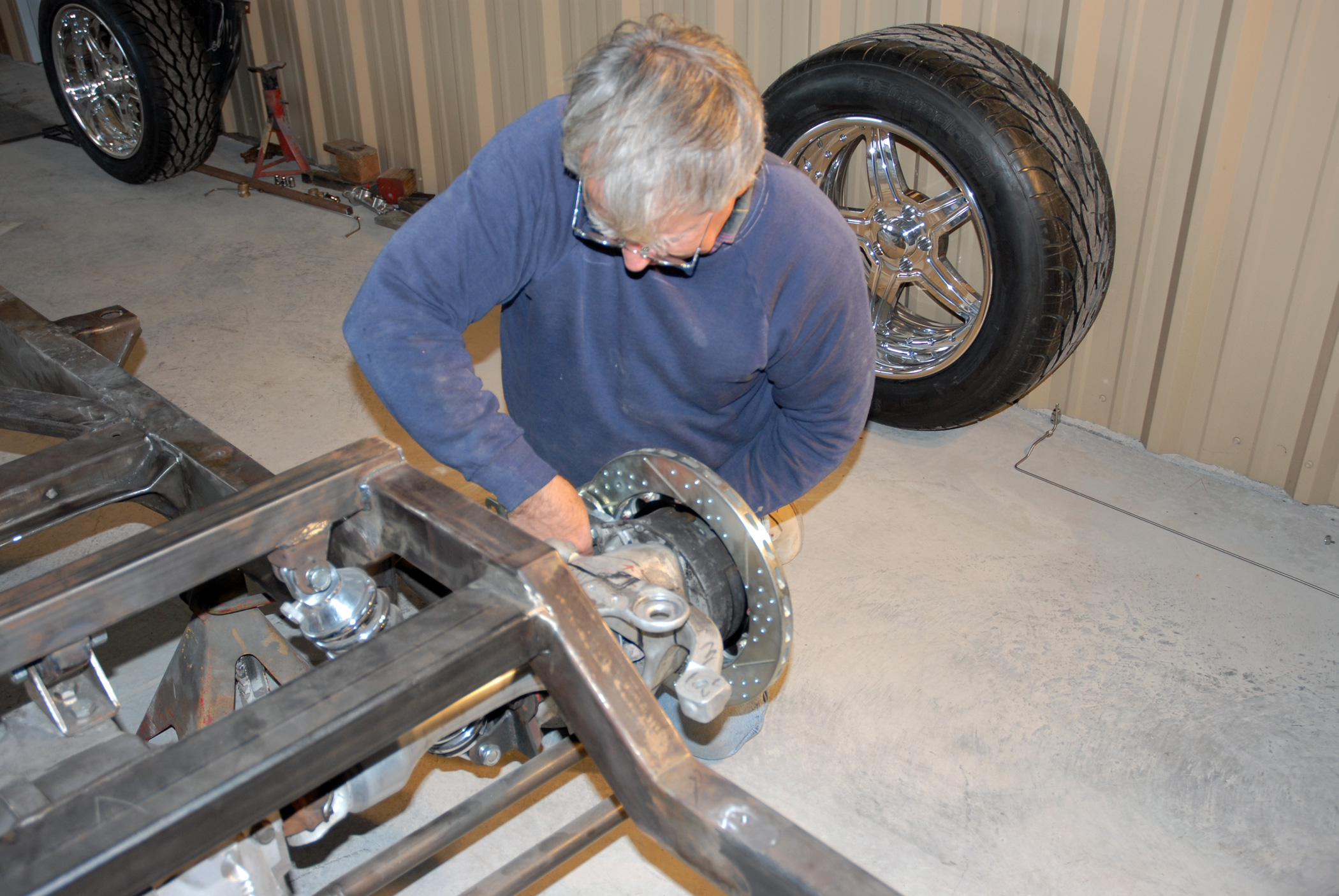
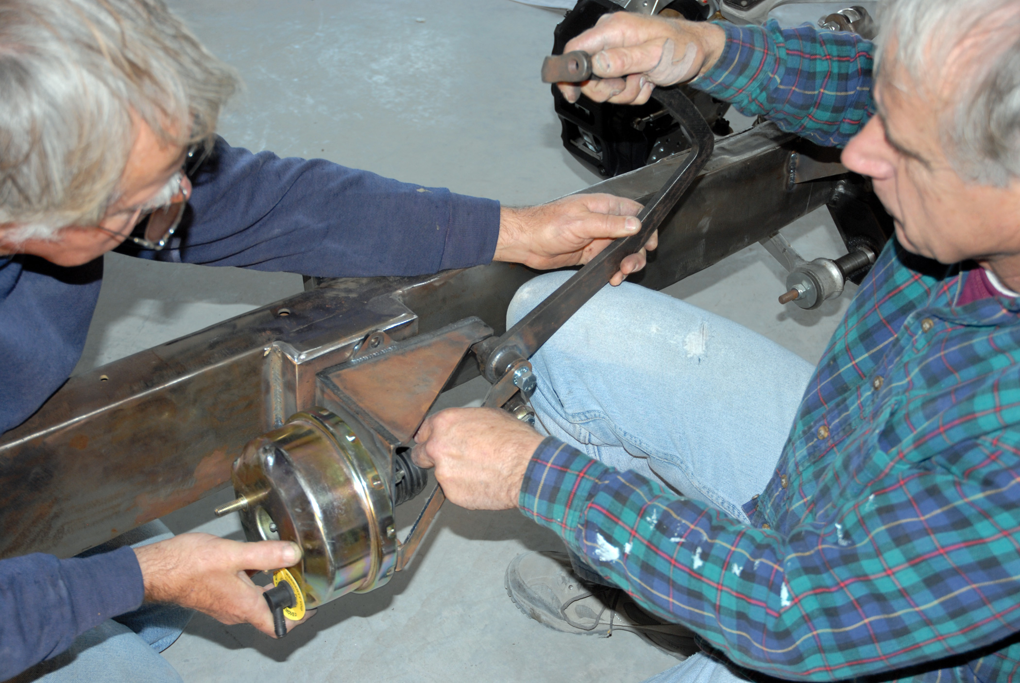
21-22. Now it’s time to install Baer’s DecelaRotors brake system on the back. However, due to the fact that we’ll be using a larger rotor, Tim installs a special “dog bone,” 1/2-inch billet aluminum disc brake caliper adapter bracket using a pair of 1/2-inch bolts.
21-22. Now it’s time to install Baer’s DecelaRotors brake system on the back. However, due to the fact that we’ll be using a larger rotor, Tim installs a special “dog bone,” 1/2-inch billet aluminum disc brake caliper adapter bracket using a pair of 1/2-inch bolts.
23. On go the Baer 13-1/3-inch cross-drilled and slotted rear rotors, as previously discussed in our text.
24-25. This is followed with the installation of the Baer DecelaRotor Corvette C4 single-piston rear caliper. Upon final assembly, Tim will final torque the 1/2-inch factory bolts to 70 ft-lb.
24-25. This is followed with the installation of the Baer DecelaRotor Corvette C4 single-piston rear caliper. Upon final assembly, Tim will final torque the 1/2-inch factory bolts to 70 ft-lb.
26-27. Tim repeats the process on the opposite side of the suspension, and this is how the semi-completed system looks.
26-27. Tim repeats the process on the opposite side of the suspension, and this is how the semi-completed system looks.
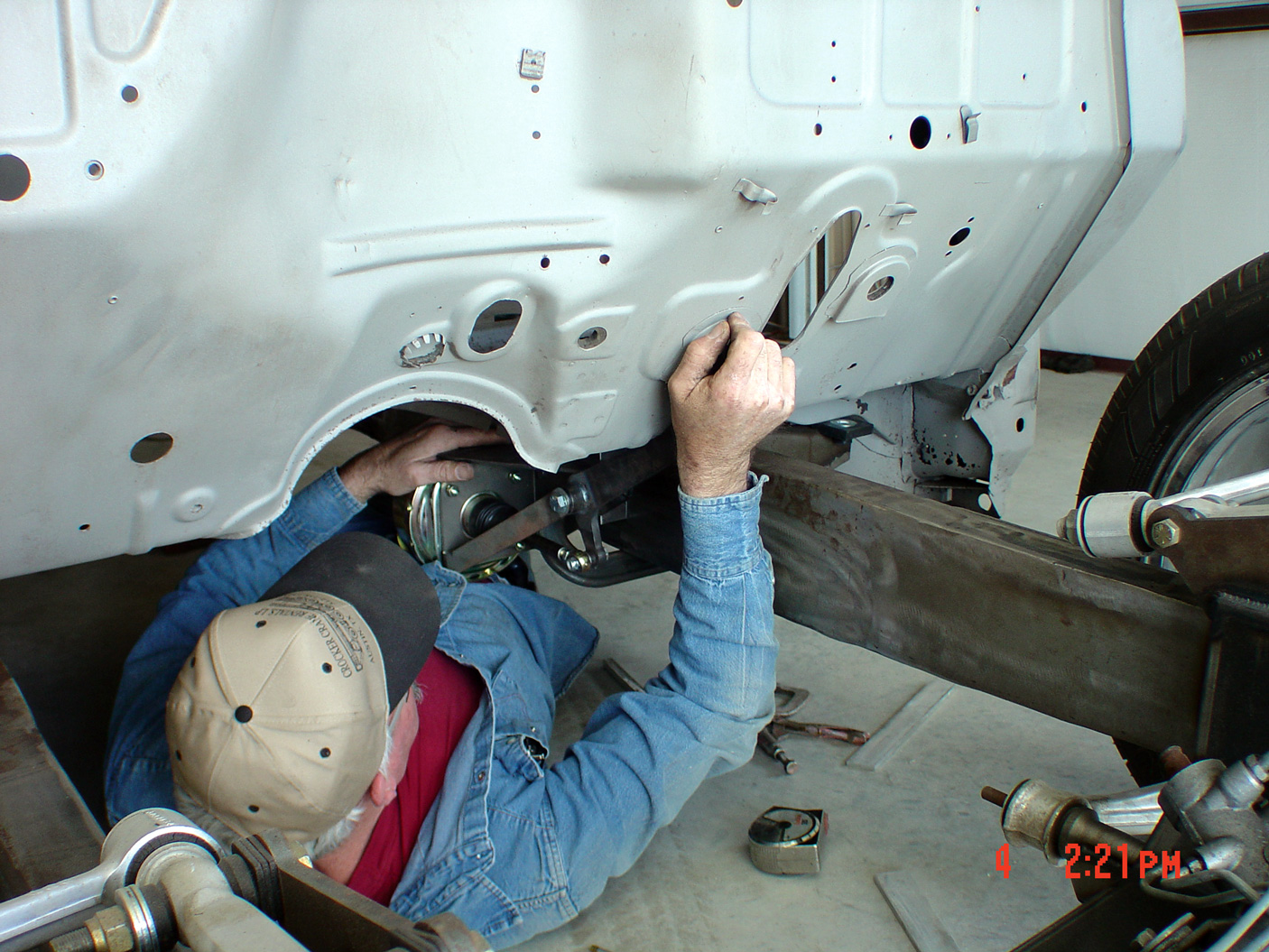
28. With the ’56 big window cab temporarily mounted on the chassis, Cimtex Rods fabricator Clayton Deal arrives at the correct (TCI) brake pedal assembly location.
29. He then fabricates a 1/4x6x4-inch mounting pad to the side of the ’56’s chassis, with a 1-1/2-inch offset to achieve the correct brake pedal geometry.
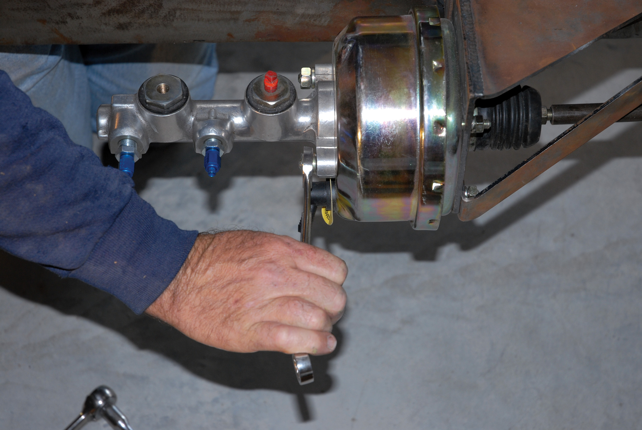
30. Here we see the Cimbanins bolting up the Total Cost Involved unit, sans the dual reservoir, using a pair of 9/16-inch mounting bolts.
31. The guys have elected to use a remote brake fluid reservoir instead, which will be hidden elsewhere in the chassis. Here we see them bolting up a Chrysler master cylinder assembly.
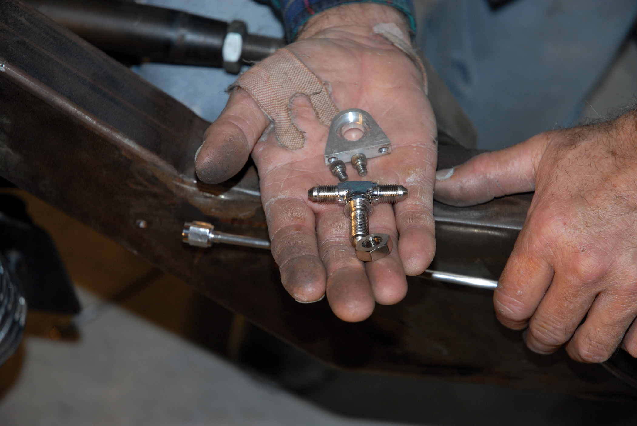
32. Here we see the approximate layout of the Russell Performance disc brake proportioning valve and Russell Performance residual valves. The residual valves are used because the master cylinder is mounted below the floorboard.
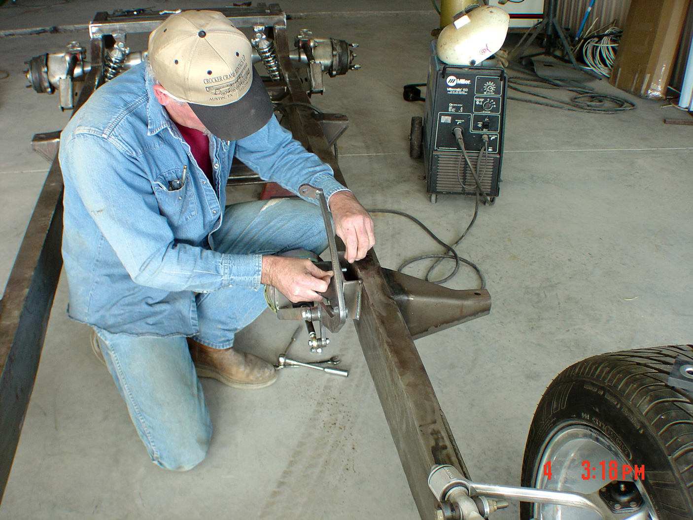
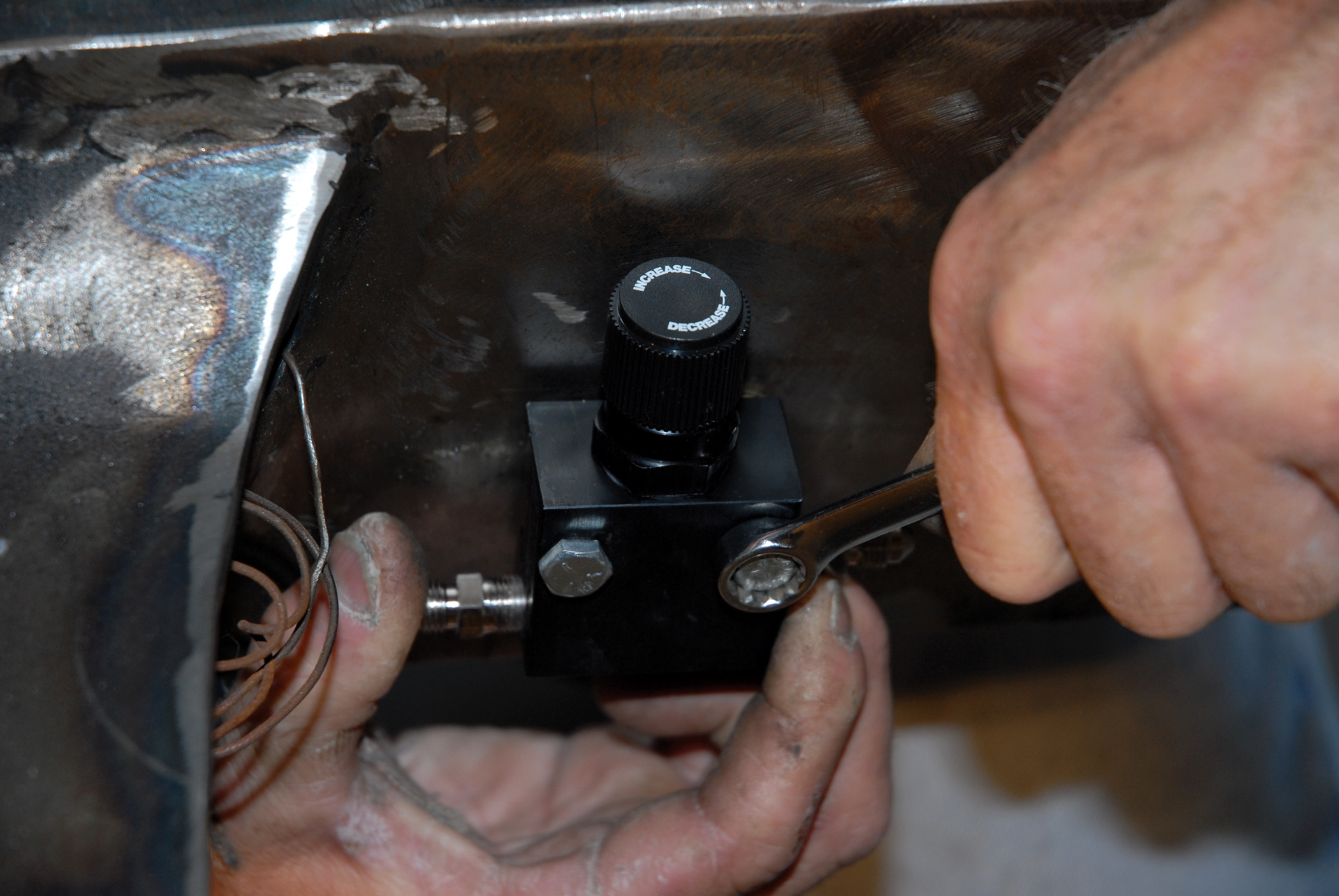
33. Mounting of the disc brake proportioning valve comes first. But before that, the Cimbanins tapped the chassis to accept a pair of 1/4x1-1/2-inch mounting bolts.
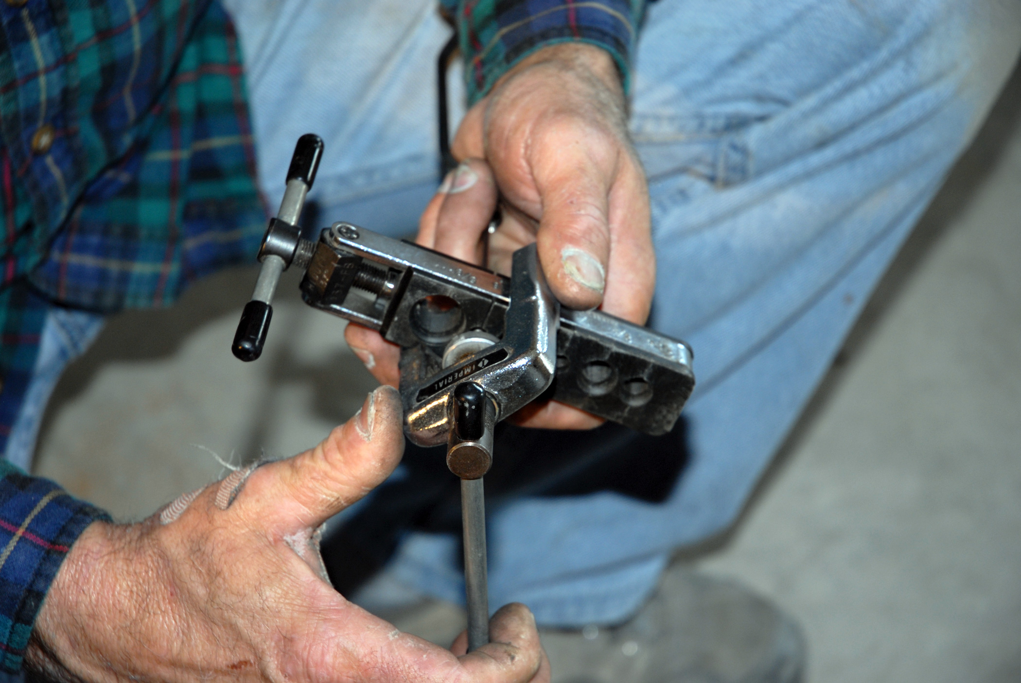
34-36. The time-consuming process of fabricating the brake line fittings begins with bending the U-shaped brake line, which will run beneath the modified front crossmember from the disc brake proportioning valve to the brakelight switch located on the opposite side of the crossmember, using Russell’s 3/16-inch AN-3 stainless fittings and couplers.
34-36. The time-consuming process of fabricating the brake line fittings begins with bending the U-shaped brake line, which will run beneath the modified front crossmember from the disc brake proportioning valve to the brakelight switch located on the opposite side of the crossmember, using Russell’s 3/16-inch AN-3 stainless fittings and couplers.
34-36. The time-consuming process of fabricating the brake line fittings begins with bending the U-shaped brake line, which will run beneath the modified front crossmember from the disc brake proportioning valve to the brakelight switch located on the opposite side of the crossmember, using Russell’s 3/16-inch AN-3 stainless fittings and couplers.
37. These lines are also held in place by Russell Performance’s 8/32-inch Allen head brake line clamps.
38. Shown are some more examples of the slick brake line hardware and clamps that Russell Performance manufactures.
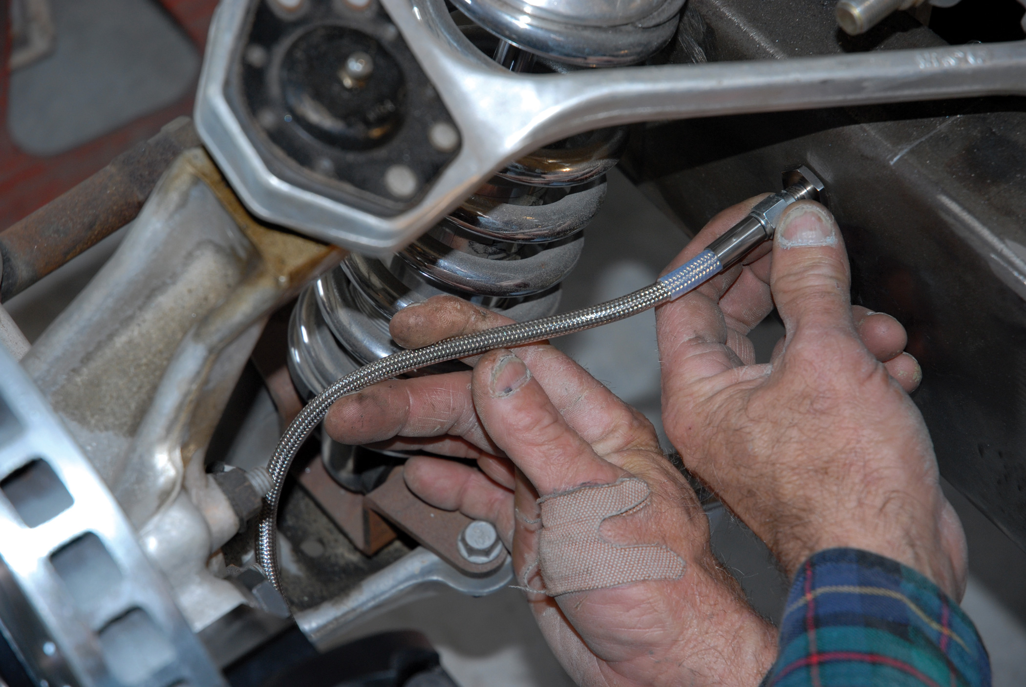
39-40. With the brake lines run to the back of the driver’s side of the chassis, Darrell Cimbanin connects the 3/16-inch Baer DecelaRotors braided brake line fitting to the T-fitting at the rear of the frame kickup.
39-40. With the brake lines run to the back of the driver’s side of the chassis, Darrell Cimbanin connects the 3/16-inch Baer DecelaRotors braided brake line fitting to the T-fitting at the rear of the frame kickup.
41-42. Next comes the bending of the crossover brake line, which runs from (rear) disc brake to disc brake.
41-42. Next comes the bending of the crossover brake line, which runs from (rear) disc brake to disc brake.
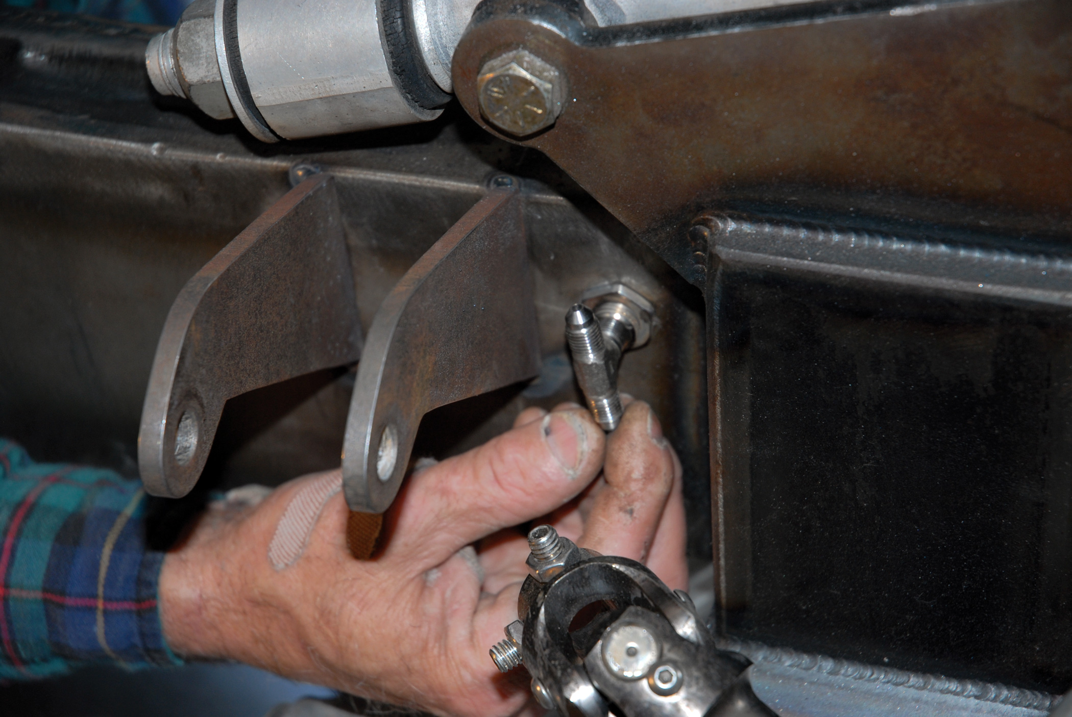
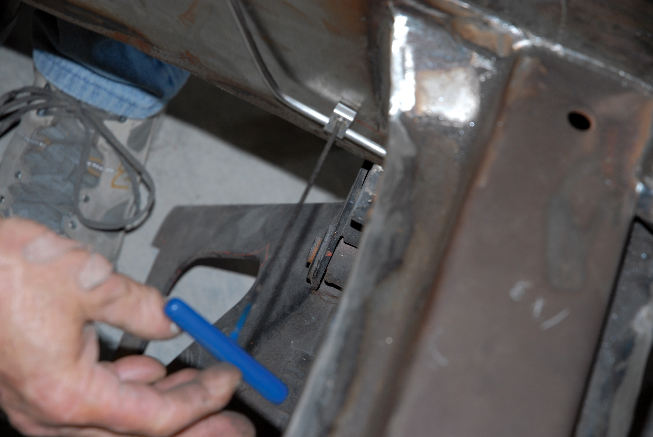
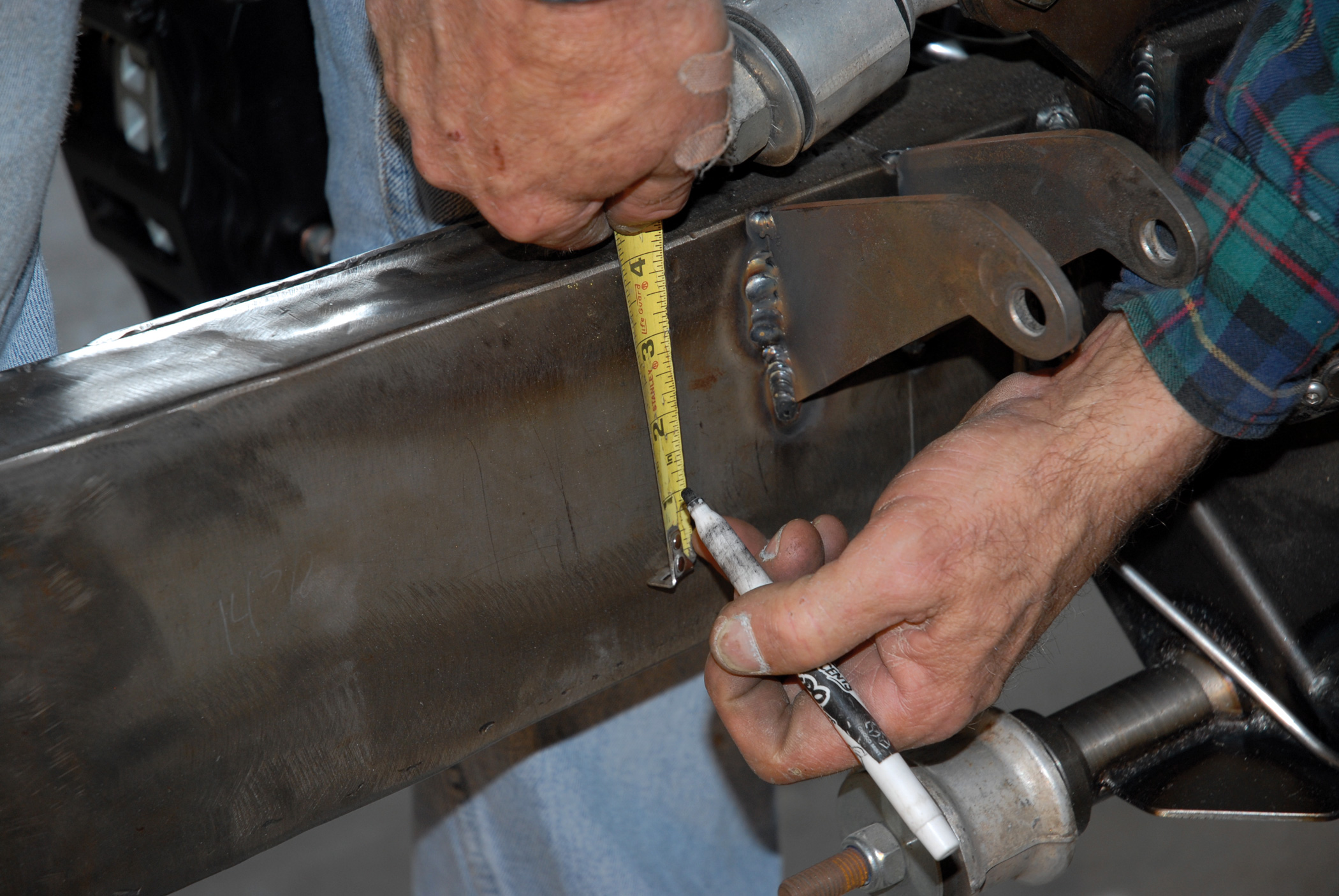
43. Now it’s time to plumb the front of the chassis. Darrell first arrives at the proper location to place the lines (approximately 4 inches down from the top rail) and proceeds to bend some tubing.
44. Shown is the tricky series of 45-degree bends that Darrell makes around the front engine mounts.
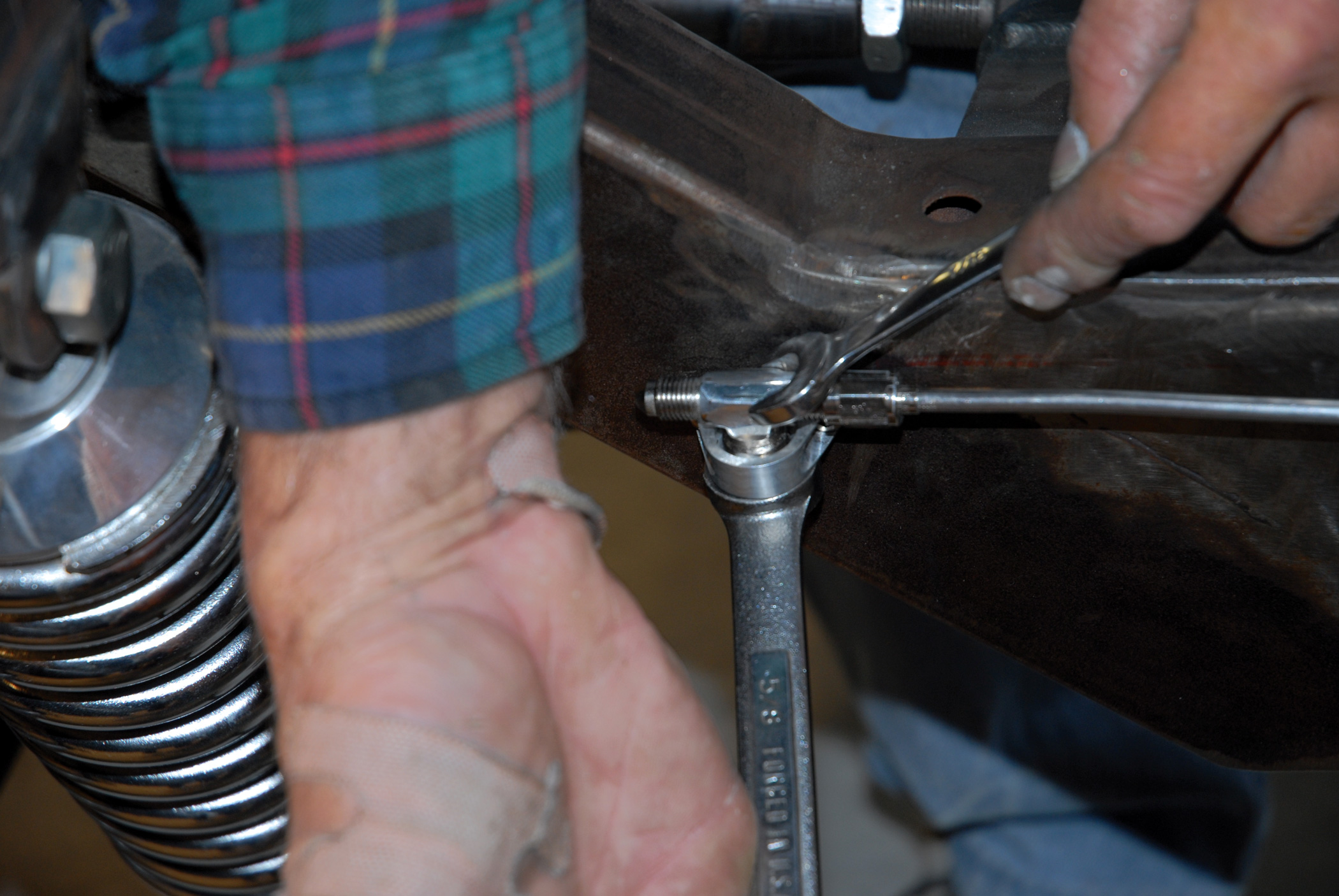
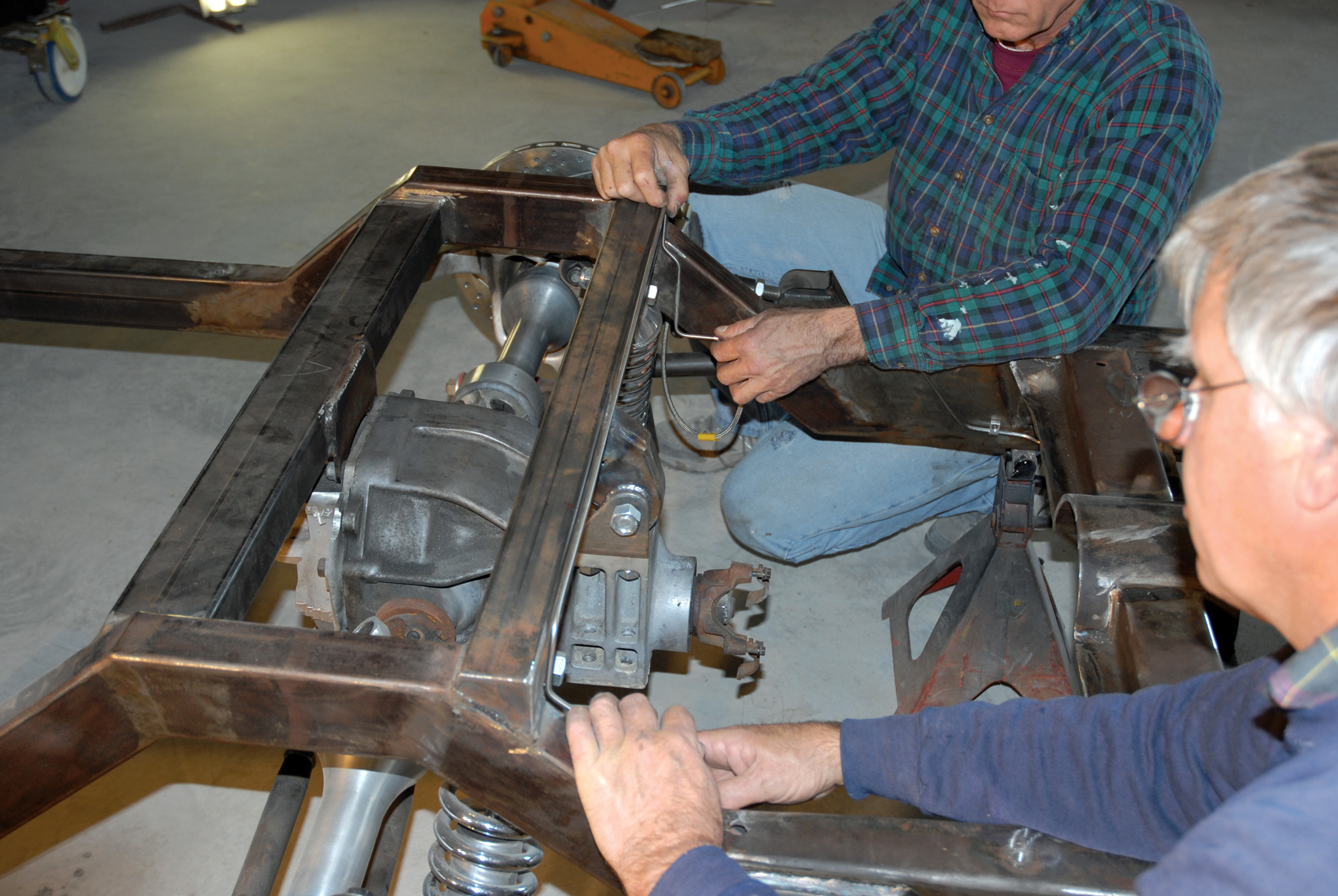
45. With the brake lines run, the next step is the installation of the Lokar Performance Products Corvette emergency brake cable kit (part No. EC-8004U) and the Corvette rear clevis kit (part No. EC-80CC).
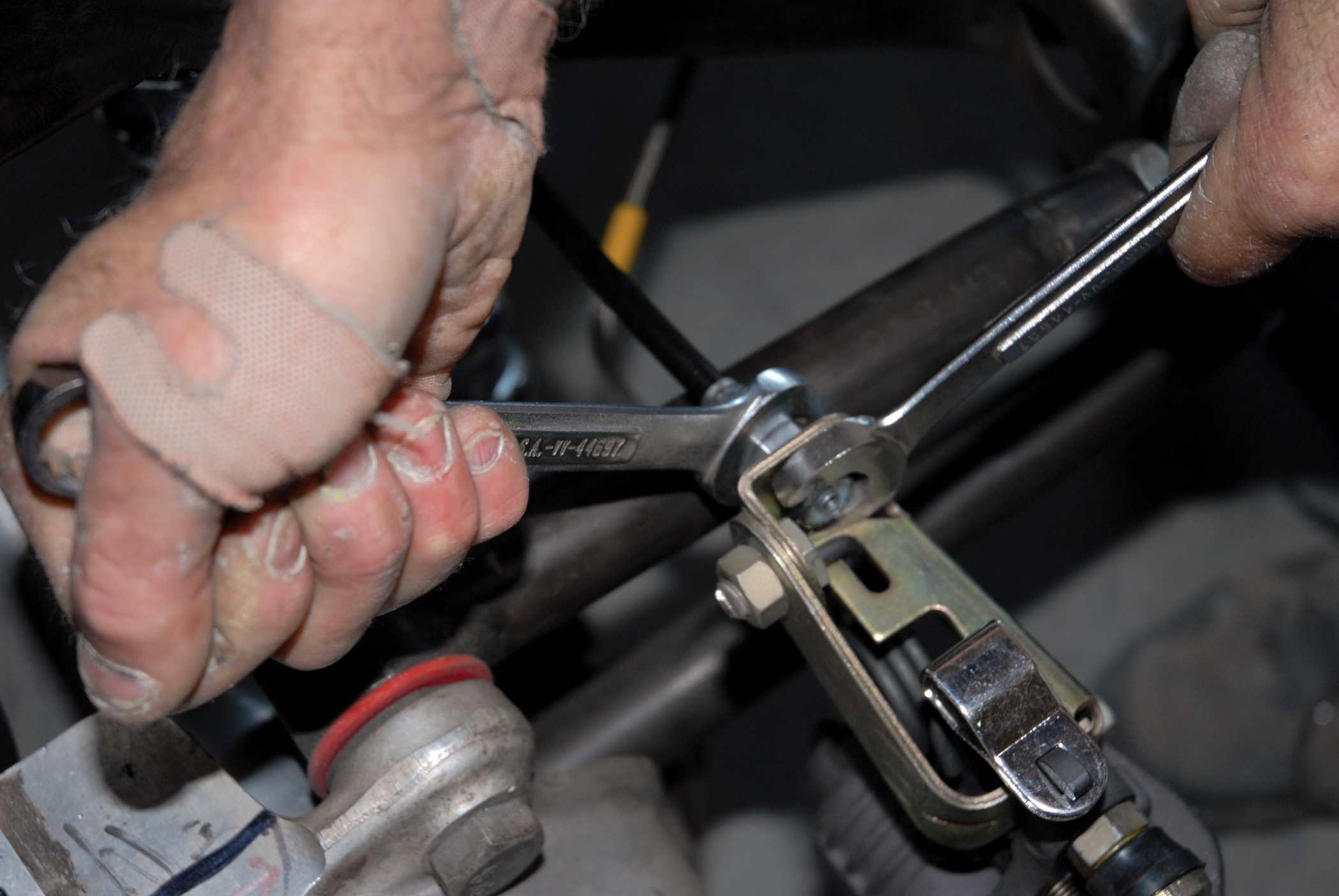
46-47. First our installer test fits the Lokar Performance Products Corvette emergency brake cable kit to the emergency brake actuator arm on the Baer DecelaRotors single-piston caliper using the Corvette rear clevis kit.
46-47. First our installer test fits the Lokar Performance Products Corvette emergency brake cable kit to the emergency brake actuator arm on the Baer DecelaRotors single-piston caliper using the Corvette rear clevis kit.
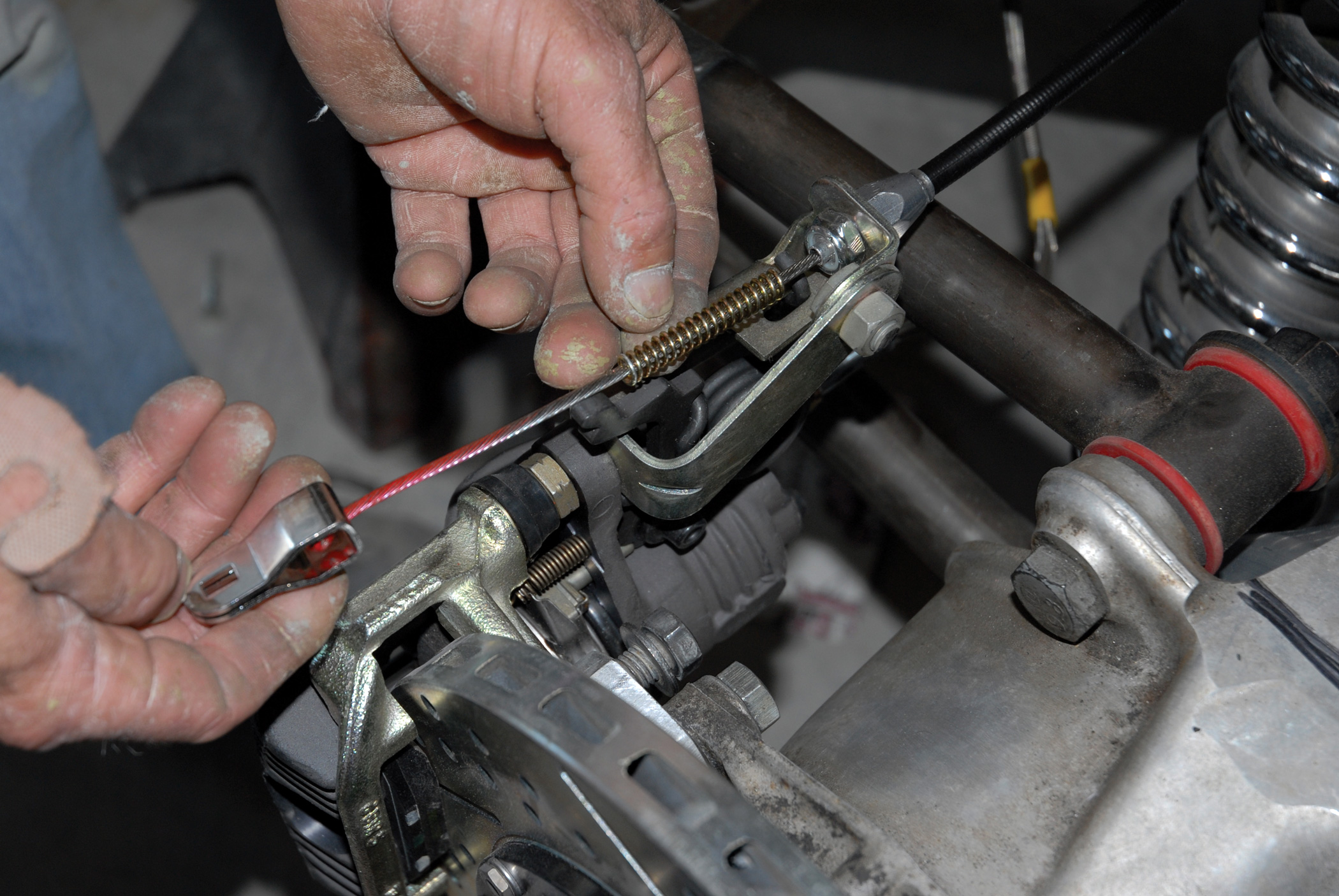
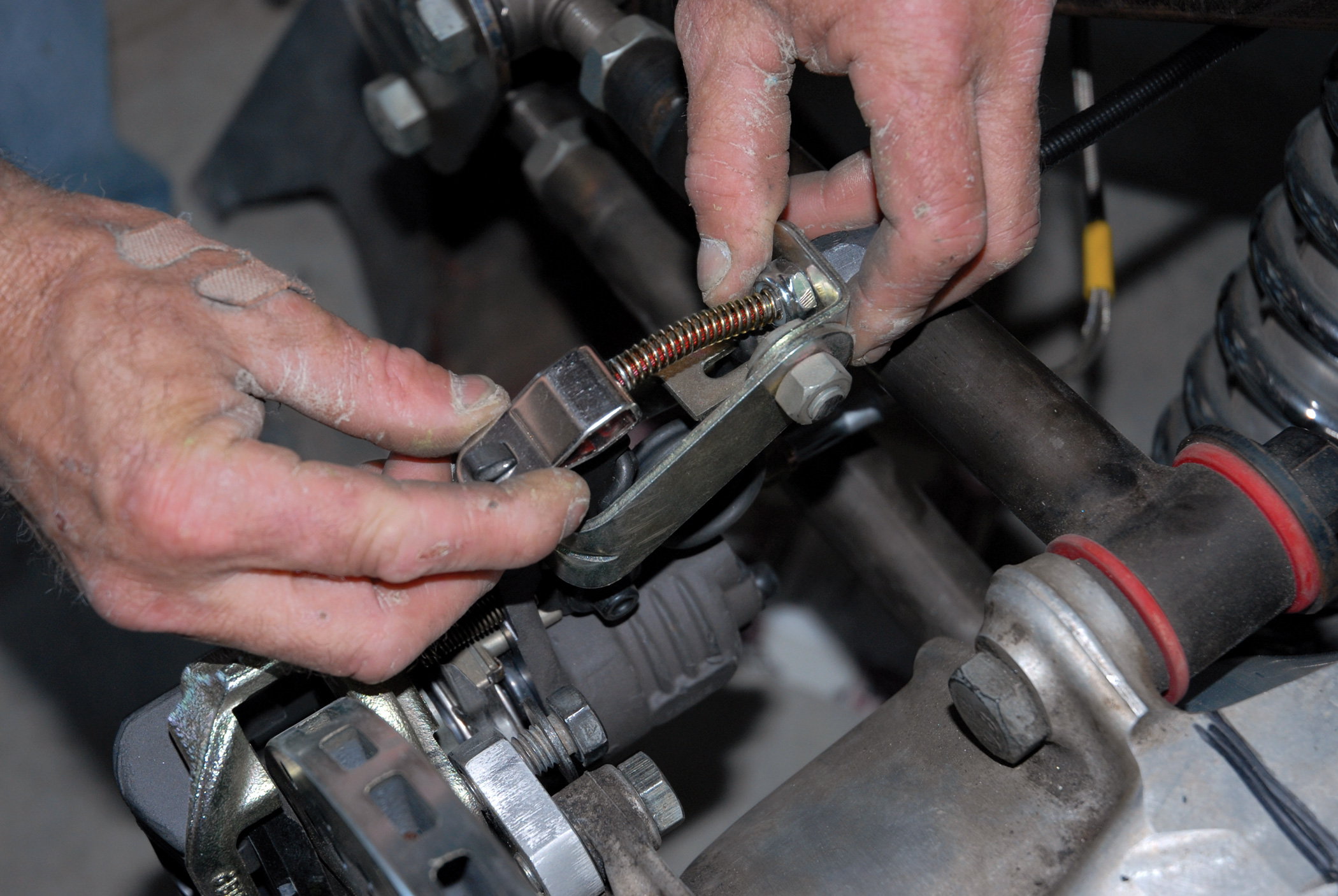
48. Once installed to the builder’s satisfaction, these units are tightened up using a pair of 3/8-inch wrenches.
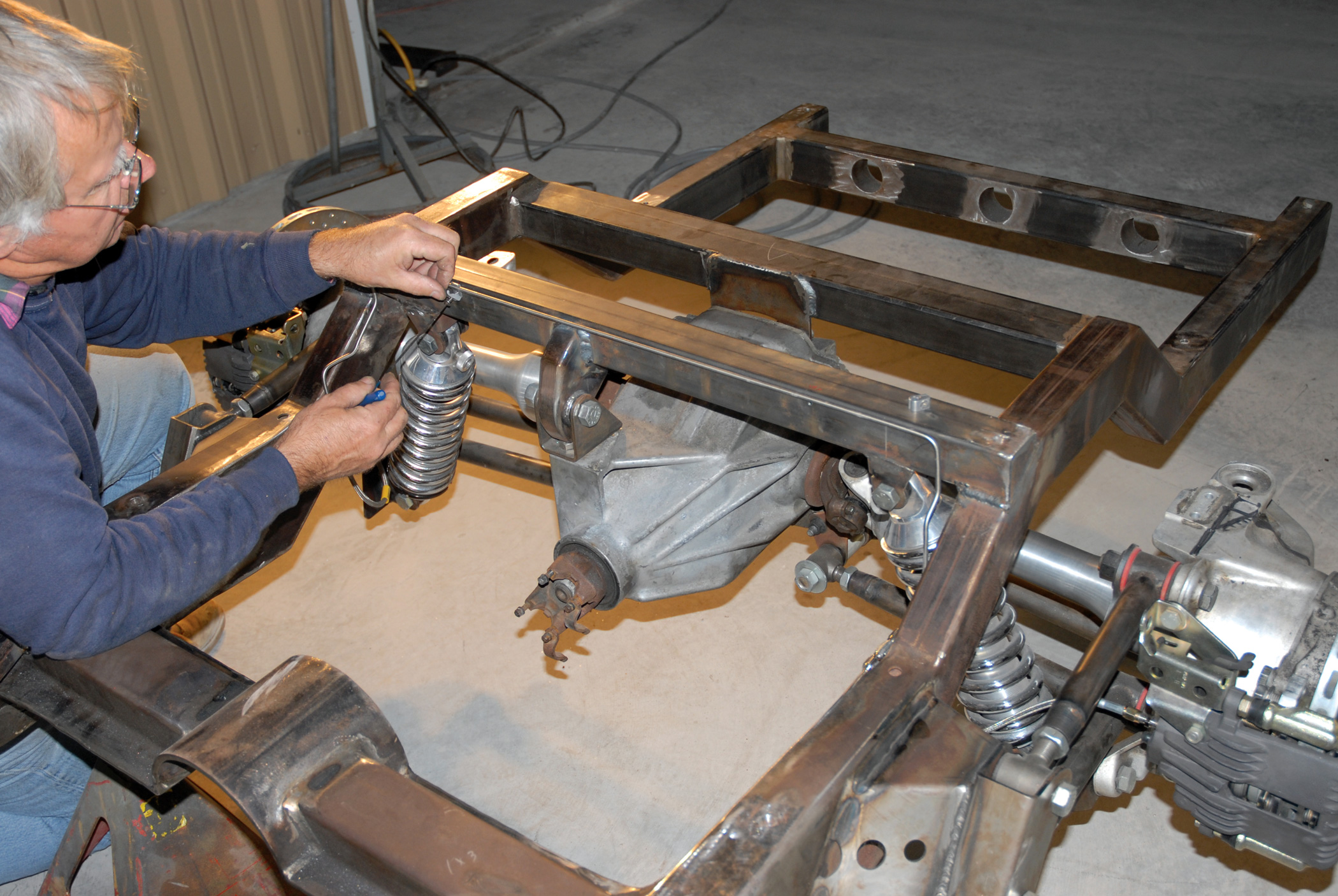
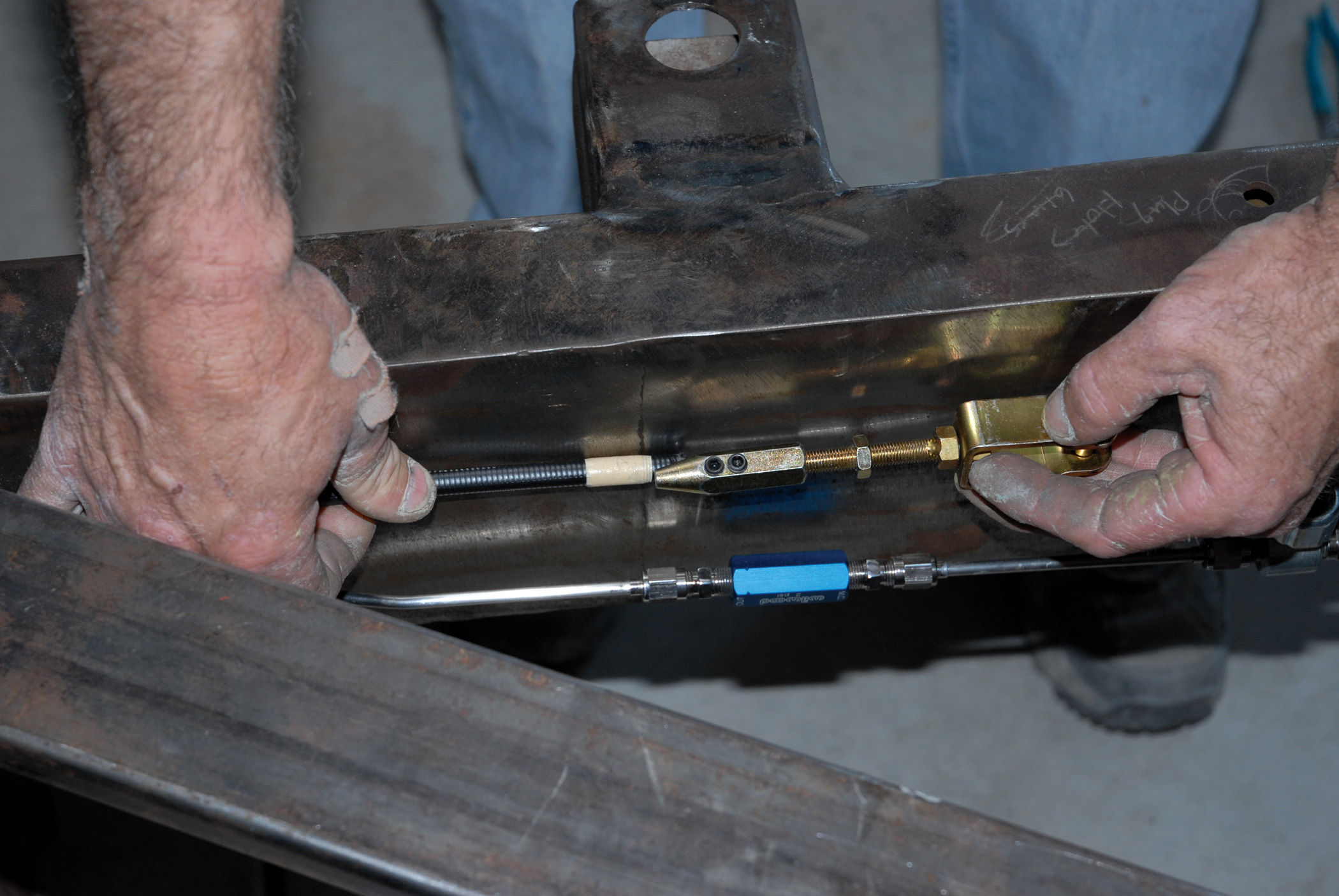
49-50. These cables are run to the forward section of the chassis, where a clevis will eventually intersect with the actual emergency brake assembly. But for now, things are left loose.
49-50. These cables are run to the forward section of the chassis, where a clevis will eventually intersect with the actual emergency brake assembly. But for now, things are left loose.
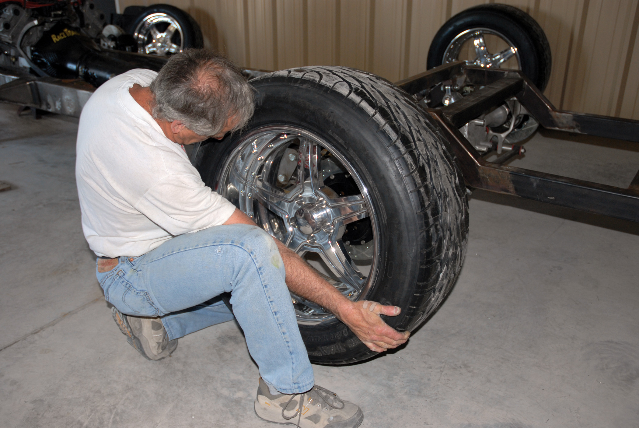
51. With the fully plumbed Baer kit installed and the lines run, the only thing that remains is to install our 18x8 and 20x10 Intro Rockman two-piece modular riveted wheels and P255/45ZR18 and P305/50ZR20 BFGoodrich KDW radial T/As. Now we’re stylin’!
ARTICLE SOURCES

BF Goodrich Tire
1049 S.W. Benschop Ave.
Port St. Lucie, FL 34953-3466
Baer Brakes
3108 W. Thomas Rd., Ste. 1201
Phoenix, AZ 85017-1411
602/352-1411
Chisenhall Companies
10614 IH-35H
San Antonio, TX 78233
210/654-6398
Cimtex Rods
P.O. Box 205
Jarrell, TX 76537
512/746-2707
Intro Wheels
1225 N Knollwood Cir,
Anaheim, CA 92801
800/454-6876
Lokar
10924 Murdock Dr.
Knoxville, TN 37932
865/966-2269
Russell Performance
(Edelbrock)
8649 Hacks Cross Rd.
Olive Branch, MS 38654
310/781-2222
Total Cost Involved Engineering Inc.
1416 W. Brooks St.
Ontario, CA 91762
800/984-6259
