Top 10 Camshaft Tips
Secrets of the Bumpstick to Help You in Your Search for More Power
Author

BOYCE HENRY
WORDS & PHOTOGRAPHY
ILLUSTRATIONS COURTESY COMP CAMS

If there is one area of a modern pushrod engine that causes more confusion than any other, it is without question the camshaft. That is not to say that our readers do not understand how a cam works—that’s the easy part. The tougher aspect regarding any camshaft is deciding exactly which cam and profile you need. Many enthusiasts aren’t quite sure what cam combination best suits their engine package, and they generally settle for someone else’s recommendation and hope for the best. Fortunately for most of us, most modern aftermarket camshaft manufacturers have very good technical departments, and some any-hour tech lines, to help walk us through the maze of profiles and valvetrain gear.
Remember, though, that when you’re equipped with the proper guidance, it isn’t all that difficult to zero in on the perfect cam profile for your particular combination. The key is to understand exactly what the engine needs to make power efficiently, and then to determine the best cam characteristics that work for your engine. To help you better understand the basics involved here, we went directly to Billy Godbold, one of the most knowledgeable camshaft experts in the industry. Through our lengthy discussions, we managed to assemble these Top 10 Camshaft Tips, designed to help you make maximum power with minimum headaches.
Godbold is a cam designer and leads the camshaft development team for Competition Cams. He regularly advises engine builders, from Top Fuel drag teams all the way down to regular Joes like you and me, who call about the specific performance of their boats. Godbold’s background is nuclear physics, but believe it or not, these days he is far more concerned with the timing and rate of opening ramps and base circle diameters than with sending rockets to some far-off galaxy. Over time he has developed a simple philosophy when it comes to matching cam timing to different engine combinations. As he put it, “An engine doesn’t care what size camshaft is in it. And it doesn’t care about any of the other valvetrain factors, like rocker ratio or how large in diameter the lifters are. All it cares about is that the intake and exhaust valves open at the proper times to allow easy flow of the air/fuel mixture and the exhaust gases, and close at the proper time to make the action in the combustion chamber as efficient as possible. Once you know how the engine needs the air/fuel mixture to move through its system, it becomes a lot easier to determine the camshaft profile and all the other pieces that you may need to make that happen.”
To help you do that, here are our Top 10 Camshaft Tips. Together, they will get you on the road to more power:
1. TUNE WITH LOBE SEPARATION
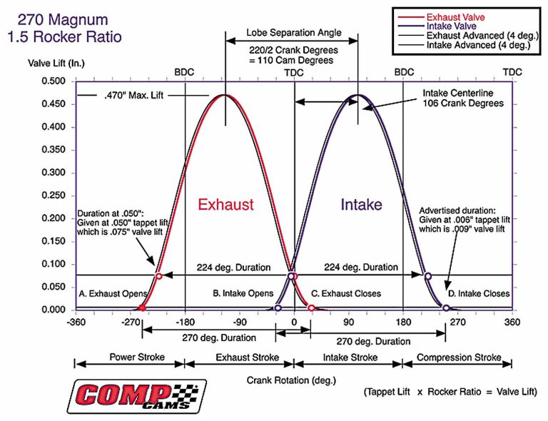
Obviously, the cam controls the timing of the intake and exhaust valve events—namely, when they open and close. These are done with separate lobes for both the intake and exhaust. Lobe separation is measured in degrees, between the peak of the exhaust lobe (maximum exhaust valve lift) and the peak of the intake lobe (maximum intake valve lift). If you test different lobe-separation angles, be aware that it also affects other important events, specifically intake opening and closing, exhaust opening and closing, and overlap. Lobe separation has no effect on duration (the amount of time the valves are open).
“Typically, if all other factors are kept constant, widening the lobe separation produces a wider, flatter torque curve that holds better at higher rpm but can sometimes have a lazy response.” Godbold goes on to explain: “Tightening the separation generally produces the opposite effect—more mid-range torque and a faster-revving engine, but with a tighter power range.”
The reason this holds true is because of the way the air/fuel mixture behaves at different rpm. When all other factors remain constant, a tighter separation means the intake valve opens and closes sooner. To visualize this, see the accompanying diagram charting a cam profile. At lower rpm, the valve stays open longer, not in degrees but in time, giving the air/fuel mixture more time to fill the cylinder so that the valve can close early. However, at high rpm the time span shortens, so an early intake valve closing hinders performance because it is more difficult to fill the cylinder simply with the low pressure created by the piston traveling down the cylinder. At this point, you are depending on the scavenging effect of the exhaust port and the inertia of the air/fuel mixture (now traveling at an extremely high velocity through the intake port) to help fill the combustion chamber. An early opening of the intake valve is not nearly as important as a later closing, because the inertia of the air/fuel mixture continues to fill the combustion chamber beyond the point that would have caused intake reversion at lower rpm.
2. TUNE THE OVERLAP FOR YOUR NEEDS
Valve overlap works almost hand in hand with lobe separation. “Overlap is defined as that part of the engine cycle when both valves are open,” Godbold says. “During this time, the exhaust and intake systems can communicate with each other. There is essentially an open path from the carburetor all the way to the mufflers. This is why changing headers often requires changing jets in the carb.”
You want a certain amount of overlap because the scavenging effect of the exhaust system can help pull the air/fuel charge into the cylinder at the start of the intake cycle. Unfortunately, different engine conditions prefer different amounts of overlap, something that isn’t adjustable once the cam has been ground. Several factors dictate how much overlap you need, and you will need to determine how you want your engine to perform before you can decide on the proper amount of overlap.
Engines with small combustion chambers typically require minimal overlap, as do engines designed to maximize low-rpm torque. In these conditions, it would be easy to send unburned fuel out the exhaust pipes, with only the smallest overlap. The opposite is true of engines designed for high-rpm horsepower or with large combustion chambers. These combinations generally require all the help they can get in filling the chamber.
Other rules of thumb include the valve angle: Canted valve and hemi-style heads promote good cross-flow between the valves and do not need as much overlap as do heads with valves that extend straighter into the cylinder (on centerline). Finally, long-rod engines also generally need less duration than engines utilizing a shorter-rod-length package. A longer rod means the piston will dwell at the top of the stroke longer, making the combustion chamber act smaller than it really is. This enhances cross-flow between the valves, multiplying the effect of the overlap period.
3. GO ROLLER (LIFTERS, THAT IS)
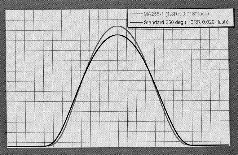
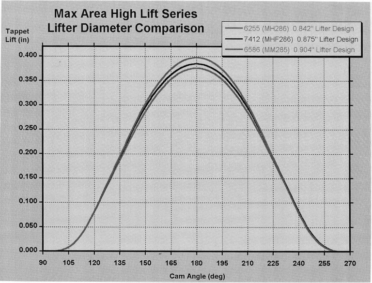
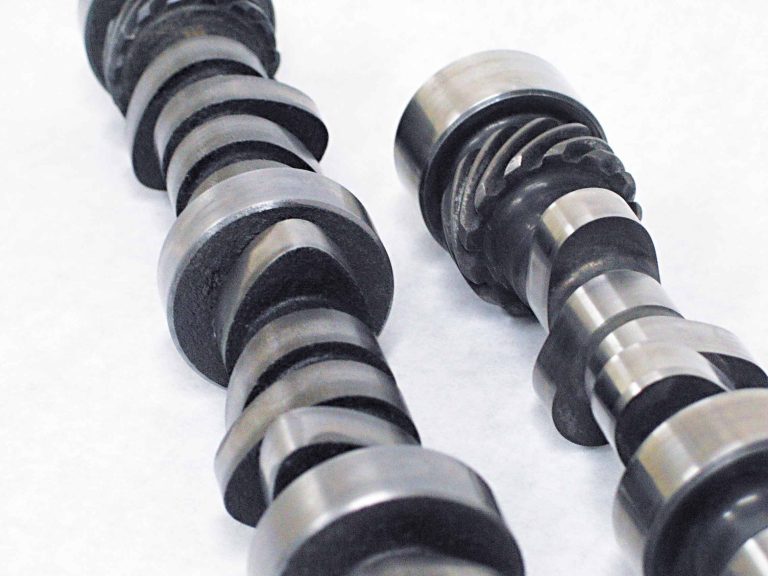
Roller lifters allow camshaft designers to do things with the cam lobes that simply are not possible on flat-tappet cam designs. The diameter of a flat-tappet lifter limits the velocity with which the cam lobe can physically lift it. This is because the opening ramp of the cam (the front of the lobe) can only be so steep before the edge of the lifter begins to dig into the lobe itself, instead of riding up and over the top. A larger-diameter flat-tappet lifter allows more velocity, but even then you can only go so far. A well-designed roller lifter does not have this problem because the roller tip will ride up just about any lobe angle. One drawback is that if the cam lobe is excessively steep, the lifter will eventually prematurely wear on the opposite side of the lifter bore, since the cam lobe is pushing it out, as well as up.
Roller lifters offer other advantages. In terms of wear, they are easier on the cam. This means you can get away with higher spring pressures without a significant reduction in cam life. Some engine builders even estimate that the reduction in parasitic losses from switching from flat-tappet to roller lifters can be as much as 12 hp. Finally, roller lifters have the advantage of interchangeability. A new flat-tappet cam must be broken in with a new set of lifters so that they will properly mate. This means that changing out a cam also requires a new set of lifters. With roller lifters, however, this is not necessary. Roller lifters do not need to be mated to the cam or a specific lobe, so they do not need to be replaced in the event of a cam swap. While this is not exactly a power tip, who couldn’t use a little advice on saving a buck?
4. USE BIGGER LIFTERS
You should already have an idea why from reading Tip No. 3. This tip is for those engine packages utilizing flat-tappet lifters. Lifters with larger diameters can be used with steeper lobe angles before the edge of the lifter digs into the side of the lobe. This translates into the ability to get more velocity into the lifter before potential failure. Increased lifter velocity (measured in inches per degree of cam rotation) means more area under the curve at all points along the cam graph. Added weight from the increased diameter of the lifter is not a primary concern because the high-ratio rocker arms that normally run in performance engines make the weight on the cam side of the rocker almost negligible. In other words, it is a win/win situation.
This does not apply to roller lifters because the limiting factor there is acceleration, not velocity, and that has nothing to do with the diameter of the lifter.
5. GET MORE LIFT
Normally, more camshaft lift helps make cylinder heads act bigger. Your goal should be to find the range where the port flows the most efficiently and maximize the time that you can hold the valve in this range. Even if a high-lift cam exceeds the lift that produces maximum flow in a port, this can still be an advantage because the valve now passes the point of maximum flow twice, nearly doubling the time spent there. The only drawback is if the cam pushes the valve into a zone that creates turbulence, which can destroy the flow pattern.
“Short-duration cams with relatively high lift provide excellent responsiveness, great torque and very good power,” Godbold says. “The result can be a very fun combination to drive. The main drawbacks to high lift have to do with dependability. One must choose the proper valve springs to handle the increased lift, and the heads must be set up to accommodate the extra clearance needed.”
6. MATCH CAM PROFILE FOR FORCED-INDUCTION SYSTEMS
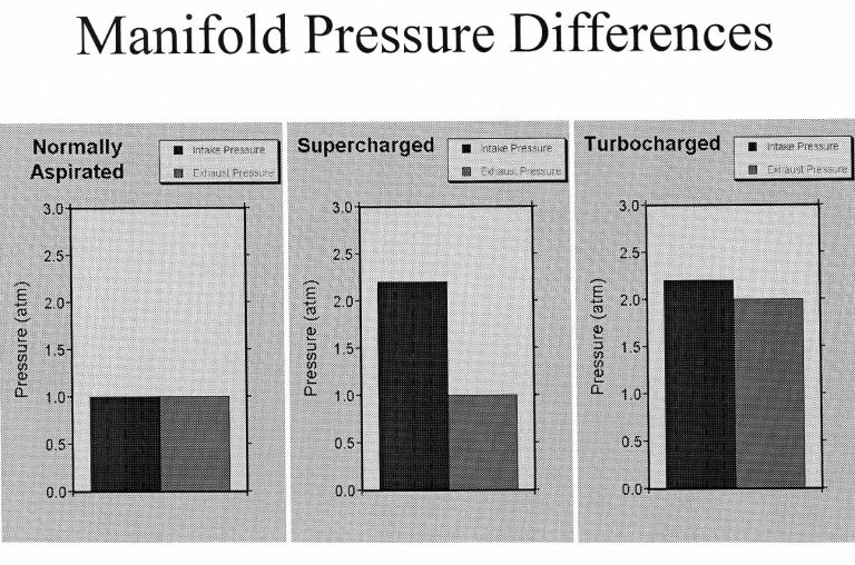
Forced-induction systems like cams with fast profiles because the increased pressure in the manifold forces the intake charge to move into the cylinder, and properly filling the cylinder is no longer a problem. Also, the increased density of the pressurized air/fuel charge means that the burn rate is increased, allowing the exhaust valve to be opened sooner to avoid pumping losses.
Be aware, however, that although turbochargers and superchargers both produce the same result—increased pressure in the combustion chamber—they achieve it in much different ways. As a result, they require different cam profiles to maximize power potential. A turbo boosts the pressure in the intake tract by harnessing the power of the exhaust gases rushing out of the port. The downside of a turbo is that backpressure is added to the system. Because of this, the ratio of air pressure in the intake tract versus the exhaust pressure in the exhaust tract is close to the ratio of a naturally aspirated engine, so overlap can still be a useful tool. A supercharger, however, is driven by a belt connected to the crankshaft. It adds parasitic losses to the engine but it does not boost backpressure. This means there is a high inlet pressure, but outlet pressure is close to atmospheric. In this situation, you want a very fast cam and have little concern for valve overlap.
7. RUN LASH LOOPS
If you are running solid lifters, one of the easiest and most effective ways to determine if a cam is right for a particular engine combination is to install it and run lash loops. It is best if you can do this on an engine dyno where gains and losses can be tracked across an entire rpm range and measured in fractions of horsepower, but that’s not to say that an experienced engine tuner can’t do it effectively with a stopwatch and a mid-week thrash at the track.
“Starting with the recommended settings, loosening and tightening the valve lash in 0.004-inch increments is one of the best ways to ask an engine what it wants,” Godbold says. Start with either the intake or exhaust valves and begin by opening up the lash for all eight valves 0.004 inch. If there is an improvement in performance, repeat the process until the engine begins losing power. Now try it again by resetting the lash to the recommended amount and start closing up the lash in 0.004-inch increments, and testing the engine that way. Be careful: Over-tightening the lash can be harmful to an engine. There’s usually plenty of wiggle room, but check with your cam manufacturer for its recommendation on minimum lash.
If you started with the intake valves, return the lash to the point where the engine performed the best and repeat the process with the exhaust valves until you have those dialed in. After this, you may want to go back and try the intakes again. Generally, if the engine performs better with the lash tightened up, that means it could use a bigger cam (more duration). If you find that the engine continues to respond the more you increase the lash, it is probably over-cammed.
8. DURATION
Now that you know how to perform lash loops, you now know the best way to determine if your selection for valve duration was correct. “Tighter lash simulates longer duration,” Godbold said. “Looser lash simulates shorter duration. Use the lash loops to zero in on the intake and exhaust durations that work best for your combination.”
As a guideline, remember that as rpm increases, the engine has more trouble effectively filling the cylinders. You can help by extending the duration that the valves are open, as well as the valve overlap. For example, to maximize flow during the exhaust stroke, race engine builders have been creeping ever higher into the compression stroke to begin cracking the exhaust valve. The idea is to have the valve nearly fully open when the exhaust stroke begins. This actually isn’t too harmful. During the power stroke, the burning fuel has used up about 80 percent of the available force on the piston by the time the crank has turned just 90 degrees.
9. LET YOUR ROCKERS DO THE WORK
No matter what type of lifter you are using, you will eventually hit the limit in terms of velocity (for flat-tappets) or acceleration (rollers). The best way to up this range is to use a higher-ratio rocker arm. The movement of the lifter remains the same, but the leverage applied by the rocker causes the valve to open more quickly and extend deeper into the cylinder to allow more flow into the combustion chamber.
“Basically, the engine doesn’t care what’s going on with the tappet—it cares what’s going on with the valve,” Godbold says. “As you go to higher rocker ratios, your tappet limits stay where they were, but your valve limits keep expanding. Now you can get much more acceleration in a roller application or much more velocity in a flat-tappet application. Basically, you are pinned in a box—this just makes the box bigger.
“The negative effect of this is that all the loads that are experienced on the cam side of the rocker are multiplied by the rocker ratio. So every time you go to a higher rocker ratio, your pushrod acts that much more flimsy. The higher rocker ratio multiplies the strength of the valve spring and requires that the cam lifter and pushrod work that much harder.”
10. DO NOT SACRIFICE WEIGHT FOR SIZE
Everything in the valvetrain is a compromise. Bigger valves can potentially mean more flow, but they can also mean more weight. Where’s the advantage if you get more flow but lose out on the redline if the added weight introduces valve float sooner? Unfortunately, there is no easy answer. Your best tool in this situation is good old common sense.
“I see this kind of stuff all the time,” Godbold says. “A guy may come in here with an LS6 head. He’s taken the stock LS6 valves out—they are probably 90 grams—and he’s replaced them with bigger valves, but they are 130 grams. He thinks he’s getting an advantage by putting a little bit bigger valves in there. The thing is that those engines come with 7mm hollow-stem, 1.9-inch intake valves. And he’s replacing it with a 2-inch valve, but it has a solid stem that’s 11/32 inch in diameter. It has got 0.200 margins, and it’s a flat-face valve. Plus, it’s got this big tulip on the backside of it. That thing is a boat anchor compared to what he had before, and the gain he has made by going 0.100 larger in the diameter of the valve is defeated by all that weight gained. I don’t see people really scrutinize weight. Grams do matter.
“Cut your margins down to the minimum. A lot of people want to run a big tulip to improve flow, but you can guarantee that is adding a ton of mass to the valve. The trick is to work on the port—especially down in that pocket and seat area—to get the air to flow well around a valve with a very flat, thin valve head. Now you will have something that takes advantage of both size and weight.”
The Cheat Sheet
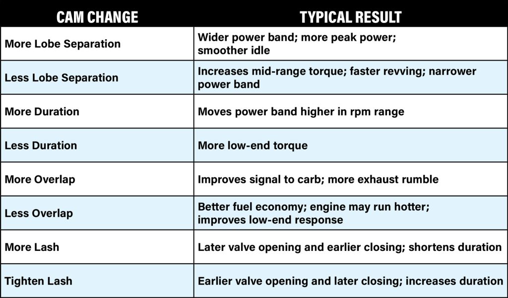
Yes, there is a lot to learn when it comes to deciding on the right camshaft for your engine, but that’s why engine builders have spent lifetimes chasing the horsepower puzzle, and there’s still more to be found. To make life a little easier, we’ve put together a list of cam changes and the typical results. Remember: Every engine combination is different, and these are just a starting point.
Spotlighter
POPULAR READS
-
Product Spotlight: Bill Mitchell Products Aluminum LS Engine Block
-
Product Spotlight: Pyramid Optimized Design Sequential Aurora Taillight for 1964½–1966 Mustang
-
PRODUCT SPOTLIGHT: 60-66 Chevy C10 Fresh Air Vent Block Off Plate
-
PRODUCT SPOTLIGHT: Cam Covers for GEN/3 Coyote from Pyramid Optimized Design
Featured
- All Post
- 20 High Priority - SR Super Rod
- Builds
- 25 High Priority - FB Ford Builder
- Cars
- 30 High Priority - AR American Rodder
- 01 Post Status
- 35 High Priority - RD Rodders Digest
- 40 High Priority - OTR On the Road
- 45 High Priority - SRB Street Rod Builder
- 50 High Priority - TB Truck Builder
- 55 High Priority - BSCENE Buckaroo Scene
- 60 High Priority - FPB Family Power Boat
- Trucks
- Swaps
- Performance Boats
- _000 Home Sliders
- Modern/Future Tech
- Builders
- 00 Sidebars
- Manufacturers
- 05 High Priority - HCI Hot Compact Imports
- 05 Publications
- 10 High Priority - CR Chevy Rumble
- Back
- Fuel System
- Electrical
- Exhaust
- Transmission / Drivetrain
- Suspension
- Steering
- Brakes
- Wheels and Tires
- Interior
- Exterior
- Accessories
- Chassis
- Engine
- Power Adders
- Back
- Transmission / Drivetrain
- Suspension
- Steering
- Brakes
- Wheels and Tires
- Interior
- Exterior
- Accessories
- Chassis
- Engine
- Fuel System
- Power Adders
- Electrical
- Exhaust
- Back
- Brakes
- Wheels and Tires
- Interior
- Exterior
- Accessories
- Chassis
- Engine
- Electrical
- Exhaust
- Fuel System
- Transmission / Drivetrain
- Suspension
- Power Adders
- Steering
- Back
- Exterior
- Accessories
- Power Adders
- Chassis
- Engine
- Electrical
- Exhaust
- Fuel System
- Transmission / Drivetrain
- Suspension
- Steering
- Brakes
- Wheels and Tires
- Interior
- Back
- Engine
- Fuel System
- Electrical
- Power Adders
- Exhaust
- Transmission / Drivetrain
- Suspension
- Steering
- Brakes
- Wheels and Tires
- Interior
- Exterior
- Accessories
- Chassis
- Back
- Fuel System
- Electrical
- Exhaust
- Transmission / Drivetrain
- Power Adders
- Suspension
- Steering
- Brakes
- Wheels and Tires
- Interior
- Exterior
- Accessories
- Chassis
- Engine
- Back
- Transmission / Drivetrain
- Suspension
- Steering
- Brakes
- Wheels and Tires
- Power Adders
- Interior
- Exterior
- Accessories
- Chassis
- Engine
- Fuel System
- Electrical
- Exhaust
- Back
- Steering
- Interior
- Accessories
- Power Adders
- Exterior and Hull
- Engine
- Fuel System
- Electrical
- Outdrives
- Back
- Power Adders
- Chassis
- Engine
- Electrical
- Exhaust
- Fuel System
- Transmission / Drivetrain
- Suspension
- Steering
- Brakes
- Wheels and Tires
- Interior
- Exterior
- Accessories
- Back
- Chrysler
- Mercury
- Subaru
- Volvo
- Volkswagen
- Chevrolet
- Cadillac
- Pontiac
- GMC
- AMC
- BMW
- Oldsmobile
- Buick
- Jeep
- Acura
- Lincoln
- Mitsubishi
- Ford
- Dodge
- Honda
- Nissan
- Toyota
- Plymouth
- Back
- 05 Pub HCI Hot Compact Imports
- 15 Pub 4x4 4x4 Builder
- 20 Pub SR Super Rod
- 25 Pub FB Ford Builder
- 30 Pub AR American Rodder
- 35 Pub RD Rodders Digest
- 40 Pub OTR On the Road
- 55 Pub BSCENE Buckaroo Scene
- 10 Pub CR Chevy Rumble
- 50 Pub TB Truck Builder
- 60 Pub FPB Family Power Boat
- 45 Pub SRB Street Rod Builder
- Back
- Steve Sellers
- Bobby Alloway
- Chip Foose
- Boyd Coddington
- Rad Rides by Troy
- Cal Auto Creations
- Ring Brothers
- George Barris
- Jesse James
- West Coast Customs
- Jack Fuller
- Carl Casper
- Bob Cullipher
- J.F. Launier
- Jerry Nichols
- Back
- Street Rods
- Hot Rods
- Late Model
- Drag Race
- Handling
- Compact Cars
- Fuel System
- Electrical
- Exhaust
- Transmission / Drivetrain
- Suspension
- Steering
- Brakes
- Wheels and Tires
- Interior
- Exterior
- Accessories
- Chassis
- Engine
- Power Adders
- Transmission / Drivetrain
- Suspension
- Steering
- Brakes
- Wheels and Tires
- Interior
- Exterior
- Accessories
- Chassis
- Engine
- Fuel System
- Power Adders
- Electrical
- Exhaust
- Brakes
- Wheels and Tires
- Interior
- Exterior
- Accessories
- Chassis
- Engine
- Electrical
- Exhaust
- Fuel System
- Transmission / Drivetrain
- Suspension
- Power Adders
- Steering
- Exterior
- Accessories
- Power Adders
- Chassis
- Engine
- Electrical
- Exhaust
- Fuel System
- Transmission / Drivetrain
- Suspension
- Steering
- Brakes
- Wheels and Tires
- Interior
- Power Adders
- Chassis
- Engine
- Electrical
- Exhaust
- Fuel System
- Transmission / Drivetrain
- Suspension
- Steering
- Brakes
- Wheels and Tires
- Interior
- Exterior
- Accessories
- Engine
- Fuel System
- Electrical
- Power Adders
- Exhaust
- Transmission / Drivetrain
- Suspension
- Steering
- Brakes
- Wheels and Tires
- Interior
- Exterior
- Accessories
- Chassis
- Back
- 05 Post Imported
- 20 Post Missing Images (All)
- 25 Post Missing Images (Partial)
- 15 Post In Progress
- 30 Post Internal Review
- 40 Post On Hold
- 27 Post Missing Content
- 50 Post Approved
- 10 Post Images Imported
- 17 Post Missing TXT Files
- 18 Post Missing PDF Files
- Back
- Chassis
- Engine Swaps
- Interior Swaps
- Driveline
- Back
- Street Trucks
- OffRoad Trucks
- Fuel System
- Electrical
- Exhaust
- Transmission / Drivetrain
- Power Adders
- Suspension
- Steering
- Brakes
- Wheels and Tires
- Interior
- Exterior
- Accessories
- Chassis
- Engine
- Transmission / Drivetrain
- Suspension
- Steering
- Brakes
- Wheels and Tires
- Power Adders
- Interior
- Exterior
- Accessories
- Chassis
- Engine
- Fuel System
- Electrical
- Exhaust
- Back
- 01 Sidebar Left
- 01 Sidebar Right
TheAutoBuilder
ARTICLE SOURCES

Comp Cams
8649 Hacks Cross Rd.
Olive Branch, MS. 38654
1-800-365-9145


