


- All Post
- 25 High Priority - FB Ford Builder
- Builds
- 30 High Priority - AR American Rodder
- Cars
- 35 High Priority - RD Rodders Digest
- 01 Post Status
- 40 High Priority - OTR On the Road
- 45 High Priority - SRB Street Rod Builder
- 50 High Priority - TB Truck Builder
- 55 High Priority - BSCENE Buckaroo Scene
- 60 High Priority - FPB Family Power Boat
- Trucks
- Swaps
- _000 Home Sliders
- Modern/Future Tech
- Performance Boats
- 00 Sidebars
- Product Spotlight
- Builders & Shows
- Manufacturers
- 05 High Priority - HCI Hot Compact Imports
- 05 Publications
- 10 High Priority - CR Chevy Rumble
- 20 High Priority - SR Super Rod
- Back
- Fuel System
- Electrical
- Exhaust
- Transmission / Drivetrain
- Suspension
- Steering
- Brakes
- Wheels and Tires
- Interior
- Exterior
- Accessories
- Street Rods
- Chassis
- Engine
- Power Adders
- Back
- Transmission / Drivetrain
- Suspension
- Steering
- Brakes
- Wheels and Tires
- Interior
- Exterior
- Accessories
- Chassis
- Engine
- Fuel System
- Power Adders
- Electrical
- Exhaust
- Back
- Brakes
- Wheels and Tires
- Interior
- Exterior
- Accessories
- Chassis
- Engine
- Electrical
- Exhaust
- Fuel System
- Transmission / Drivetrain
- Suspension
- Power Adders
- Steering
- Back
- Exterior
- Accessories
- Power Adders
- Chassis
- Engine
- Electrical
- Exhaust
- Fuel System
- Transmission / Drivetrain
- Suspension
- Steering
- Brakes
- Wheels and Tires
- Interior
- Back
- Engine
- Fuel System
- Electrical
- Power Adders
- Exhaust
- Transmission / Drivetrain
- Suspension
- Steering
- Brakes
- Wheels and Tires
- Interior
- Exterior
- Accessories
- Chassis
- Back
- Fuel System
- Electrical
- Exhaust
- Transmission / Drivetrain
- Power Adders
- Suspension
- Steering
- Brakes
- Wheels and Tires
- Interior
- Exterior
- Accessories
- Chassis
- Engine
- Back
- Transmission / Drivetrain
- Suspension
- Steering
- Brakes
- Wheels and Tires
- Power Adders
- Interior
- Exterior
- Accessories
- Chassis
- Engine
- Fuel System
- Electrical
- Exhaust
- Back
- Steering
- Interior
- Accessories
- Power Adders
- Exterior and Hull
- Engine
- Fuel System
- Electrical
- Outdrives
- Back
- Power Adders
- Chassis
- Engine
- Electrical
- Exhaust
- Fuel System
- Transmission / Drivetrain
- Suspension
- Steering
- Brakes
- Wheels and Tires
- Interior
- Exterior
- Accessories
- Back
- Chrysler
- Subaru
- Volvo
- Volkswagen
- Chevrolet
- Cadillac
- Pontiac
- GMC
- Oldsmobile
- AMC
- BMW
- Buick
- Acura
- Jeep
- Lincoln
- Mitsubishi
- Ford
- Dodge
- Toyota
- Honda
- Nissan
- Plymouth
- Mercury
- Back
- 15 Pub 4x4 4x4 Builder
- 20 Pub SR Super Rod
- 25 Pub FB Ford Builder
- 30 Pub AR American Rodder
- 35 Pub RD Rodders Digest
- 40 Pub OTR On the Road
- 55 Pub BSCENE Buckaroo Scene
- 10 Pub CR Chevy Rumble
- 50 Pub TB Truck Builder
- 60 Pub FPB Family Power Boat
- 45 Pub SRB Street Rod Builder
- 05 Pub HCI Hot Compact Imports
- Back
- Steve Sellers
- Bobby Alloway
- Chip Foose
- Boyd Coddington
- Rad Rides by Troy
- Cal Auto Creations
- George Barris
- Ring Brothers
- Jesse James
- West Coast Customs
- Carl Casper
- Jack Fuller
- J.F. Launier
- Bob Cullipher
- Jerry Nichols
- Back
- Street Rods
- Hot Rod/Muscle Car
- Late Model, Future Tech, & Other News
- Drag Race
- Handling
- Compact Cars
- Fuel System
- Electrical
- Exhaust
- Transmission / Drivetrain
- Suspension
- Steering
- Brakes
- Wheels and Tires
- Interior
- Exterior
- Accessories
- Street Rods
- Chassis
- Engine
- Power Adders
- Transmission / Drivetrain
- Suspension
- Steering
- Brakes
- Wheels and Tires
- Interior
- Exterior
- Accessories
- Chassis
- Engine
- Fuel System
- Power Adders
- Electrical
- Exhaust
- Brakes
- Wheels and Tires
- Interior
- Exterior
- Accessories
- Chassis
- Engine
- Electrical
- Exhaust
- Fuel System
- Transmission / Drivetrain
- Suspension
- Power Adders
- Steering
- Exterior
- Accessories
- Power Adders
- Chassis
- Engine
- Electrical
- Exhaust
- Fuel System
- Transmission / Drivetrain
- Suspension
- Steering
- Brakes
- Wheels and Tires
- Interior
- Power Adders
- Chassis
- Engine
- Electrical
- Exhaust
- Fuel System
- Transmission / Drivetrain
- Suspension
- Steering
- Brakes
- Wheels and Tires
- Interior
- Exterior
- Accessories
- Engine
- Fuel System
- Electrical
- Power Adders
- Exhaust
- Transmission / Drivetrain
- Suspension
- Steering
- Brakes
- Wheels and Tires
- Interior
- Exterior
- Accessories
- Chassis
- Back
- 05 Post Imported
- 20 Post Missing Images (All)
- 25 Post Missing Images (Partial)
- 15 Post In Progress
- 30 Post Internal Review
- 27 Post Missing Content
- 40 Post On Hold
- 50 Post Approved
- 17 Post Missing TXT Files
- 18 Post Missing PDF Files
- Back
- Chassis
- Engine Swaps
- Interior Swaps
- Driveline
- Back
- Street Trucks
- OffRoad Trucks
- Fuel System
- Electrical
- Exhaust
- Transmission / Drivetrain
- Power Adders
- Suspension
- Steering
- Brakes
- Wheels and Tires
- Interior
- Exterior
- Accessories
- Chassis
- Engine
- Transmission / Drivetrain
- Suspension
- Steering
- Brakes
- Wheels and Tires
- Power Adders
- Interior
- Exterior
- Accessories
- Chassis
- Engine
- Fuel System
- Electrical
- Exhaust
- Back
- 01 Sidebar Left
- 01 Sidebar Right

Today’s 4x4s have become extremely specialized. At one end of the spectrum are one-off, purpose-built, non-street-legal rock buggies. These are the cream of the rock crop. Most have tube chassis with what seems like nearly 360 degrees of axle articulation. Often the transfer cases are doubled up to produce crawl ratios way beyond the once magical 100:1. They’re obviously awesome, and capable of handling boulders as if they were speed bumps.
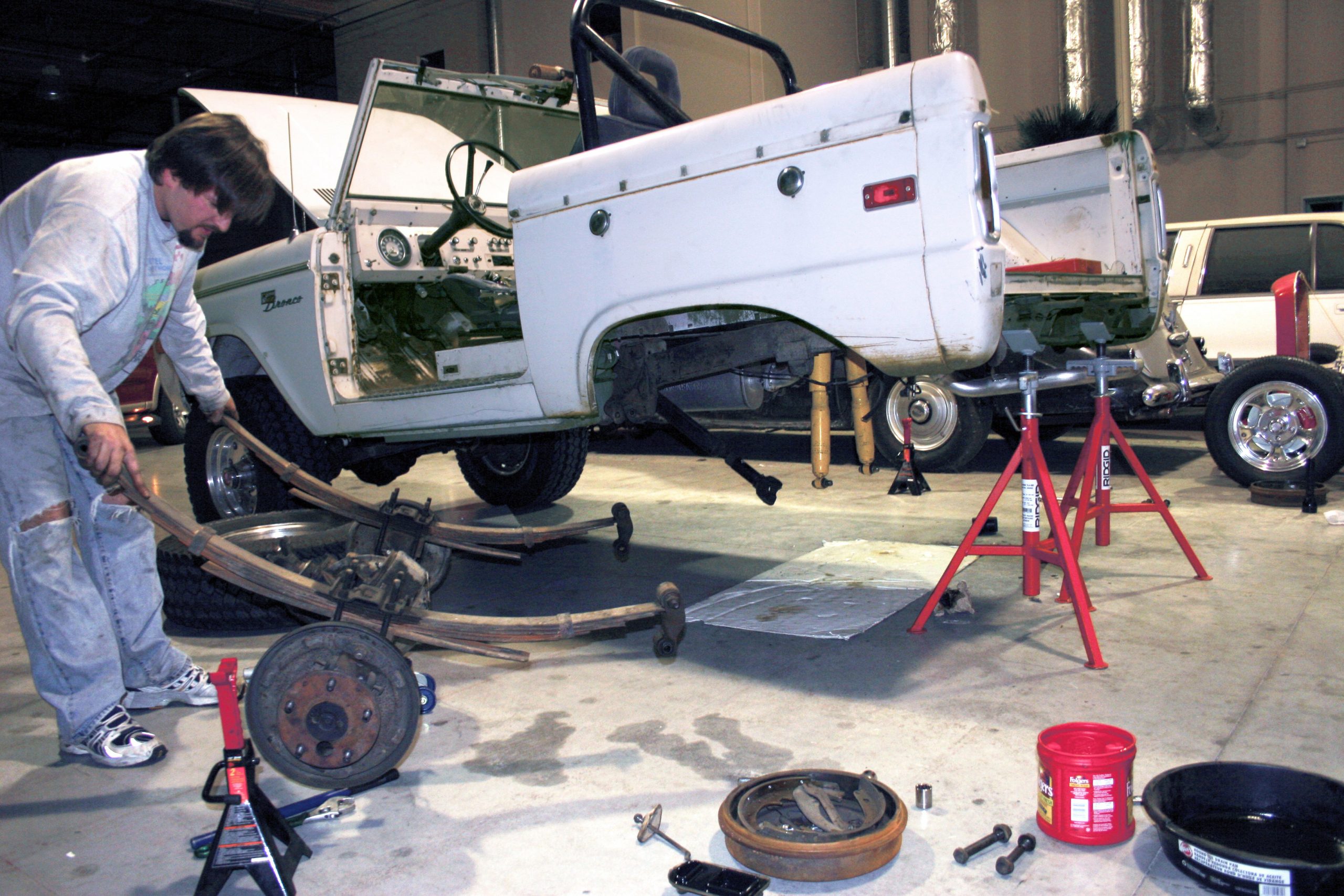
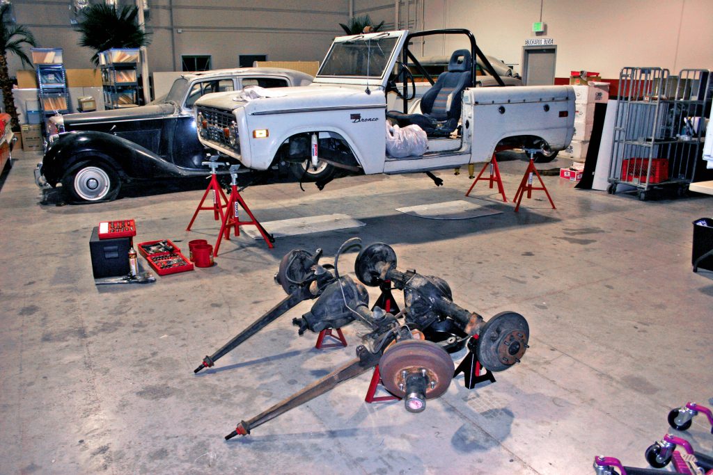
On the opposing end of the spectrum are the more common leather-clad, urban SUVs with their multiple DVD players and chromed 20-inch wheels. Steven Llorca wanted something more in the middle of these two extremes. Well, maybe not quite the middle; more like just a couple of notches to the street-legal side of the rock-buggy camp. He wanted a serious rocker capable of driving to the office and to the trail. What better project platform than the early Ford Bronco, which is arguably credited with starting both the SUV and the off-roading crazes?
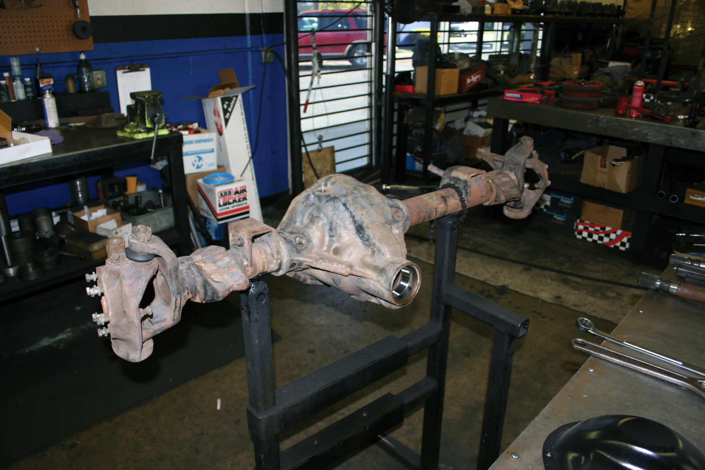
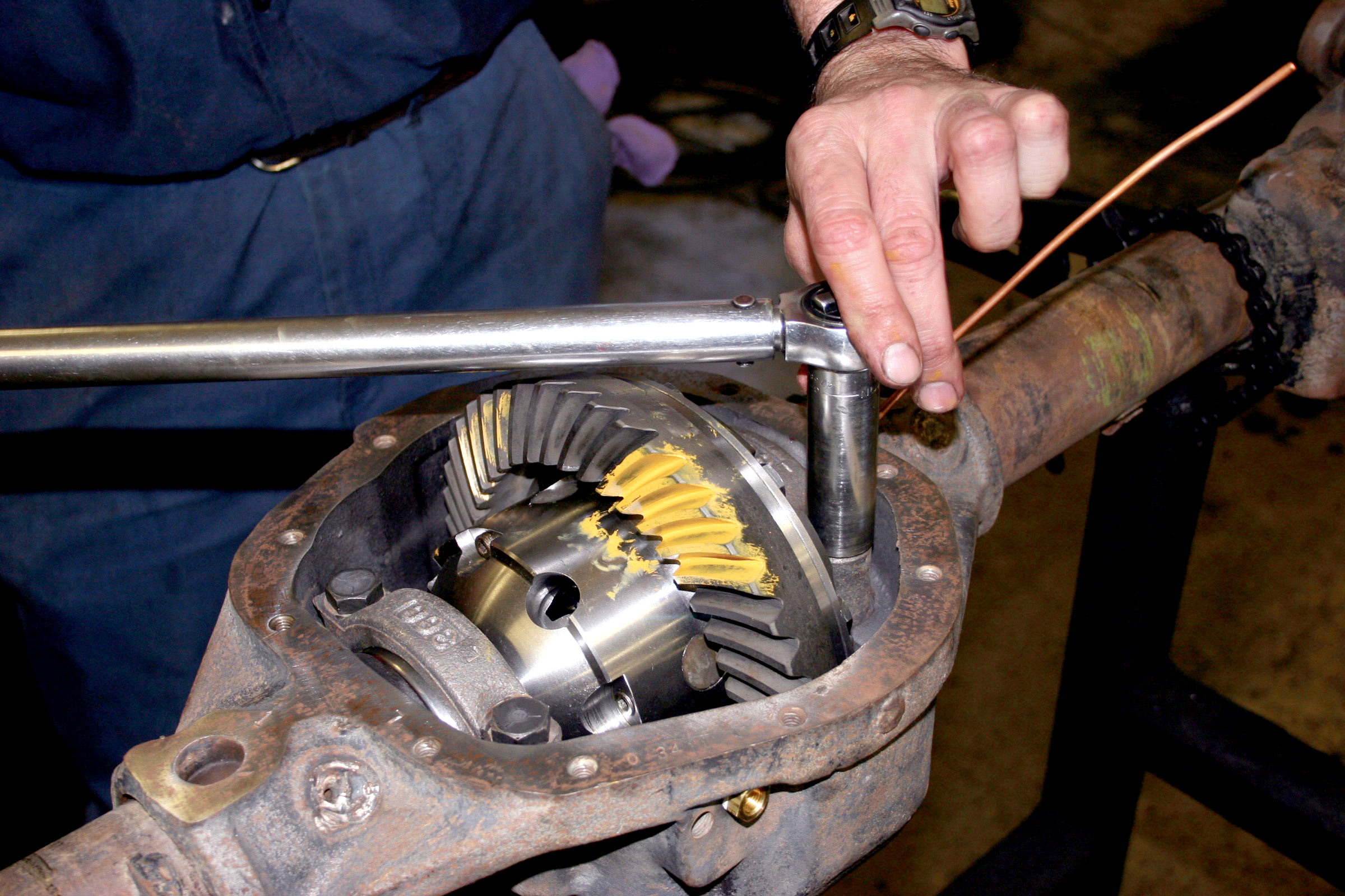
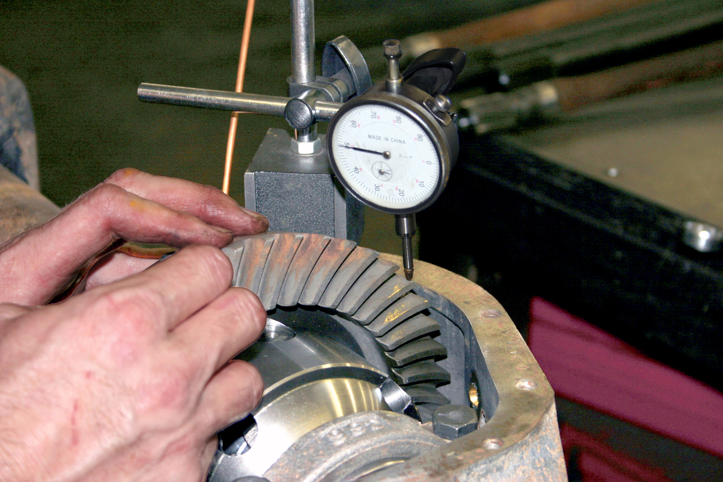
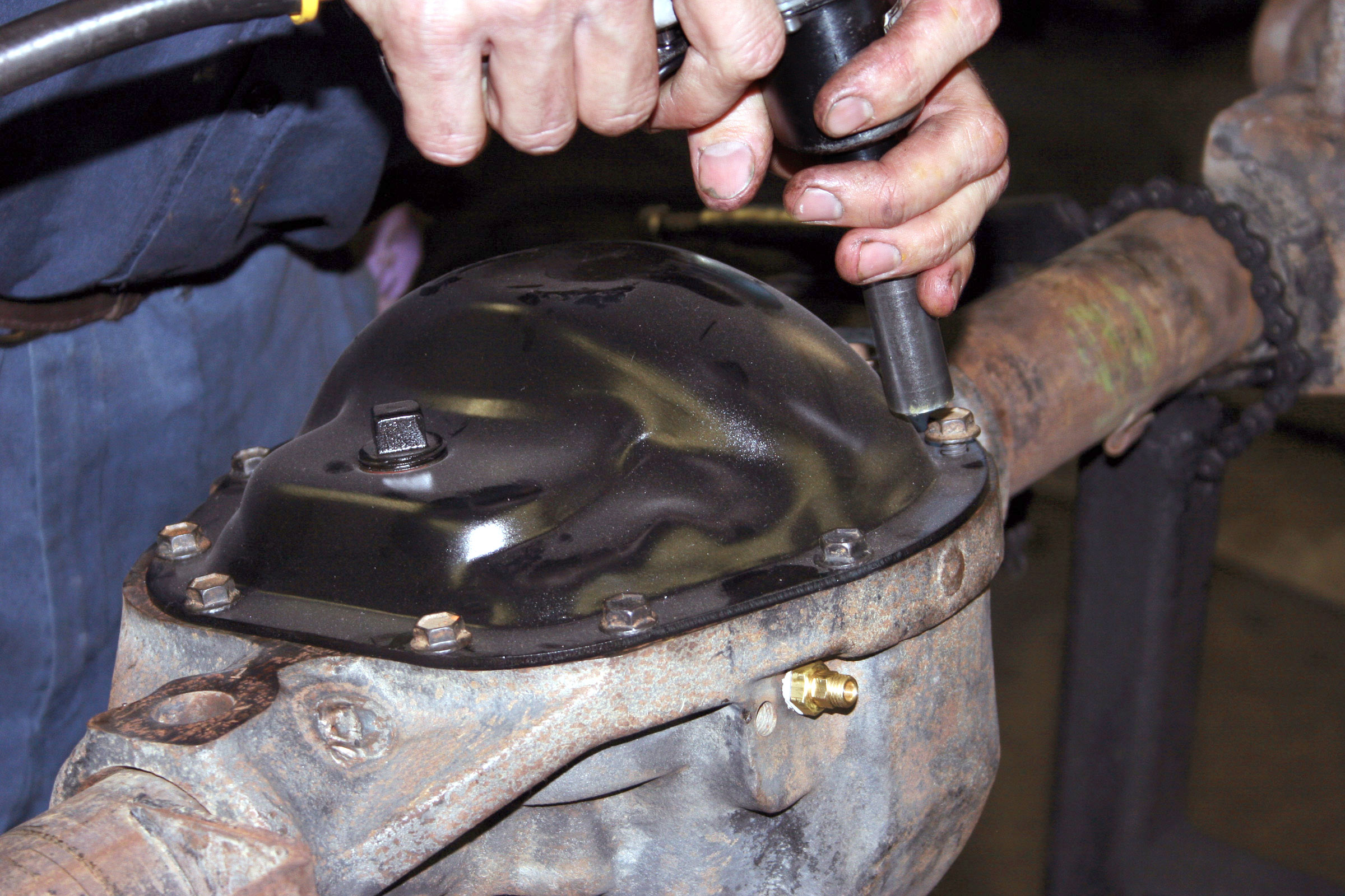
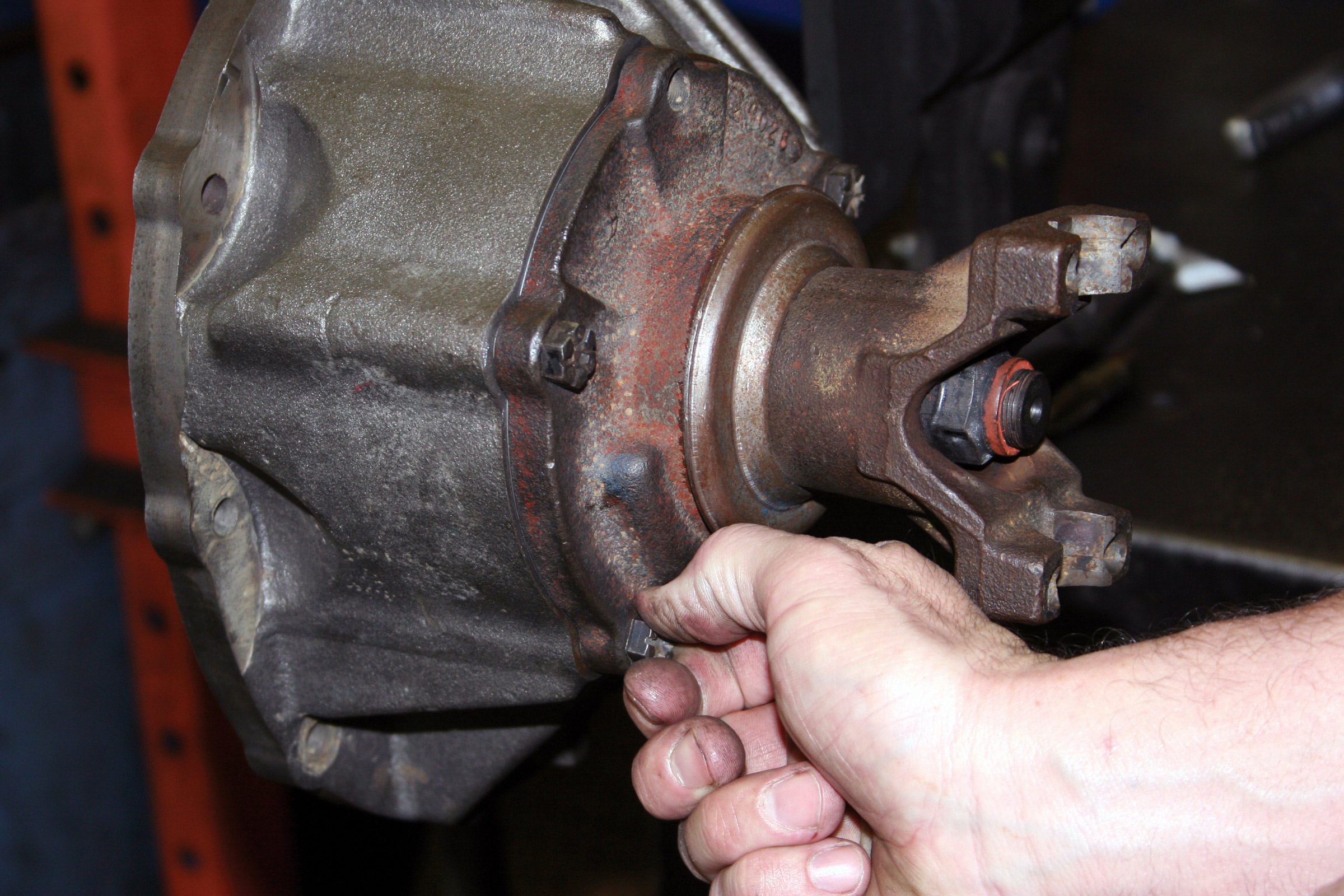
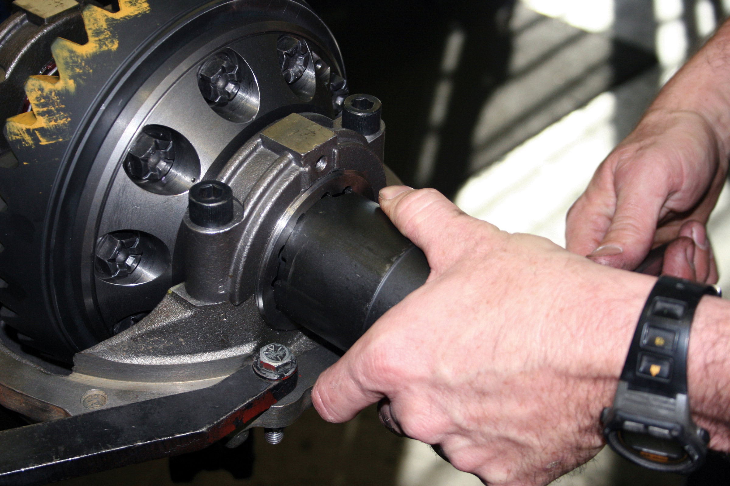
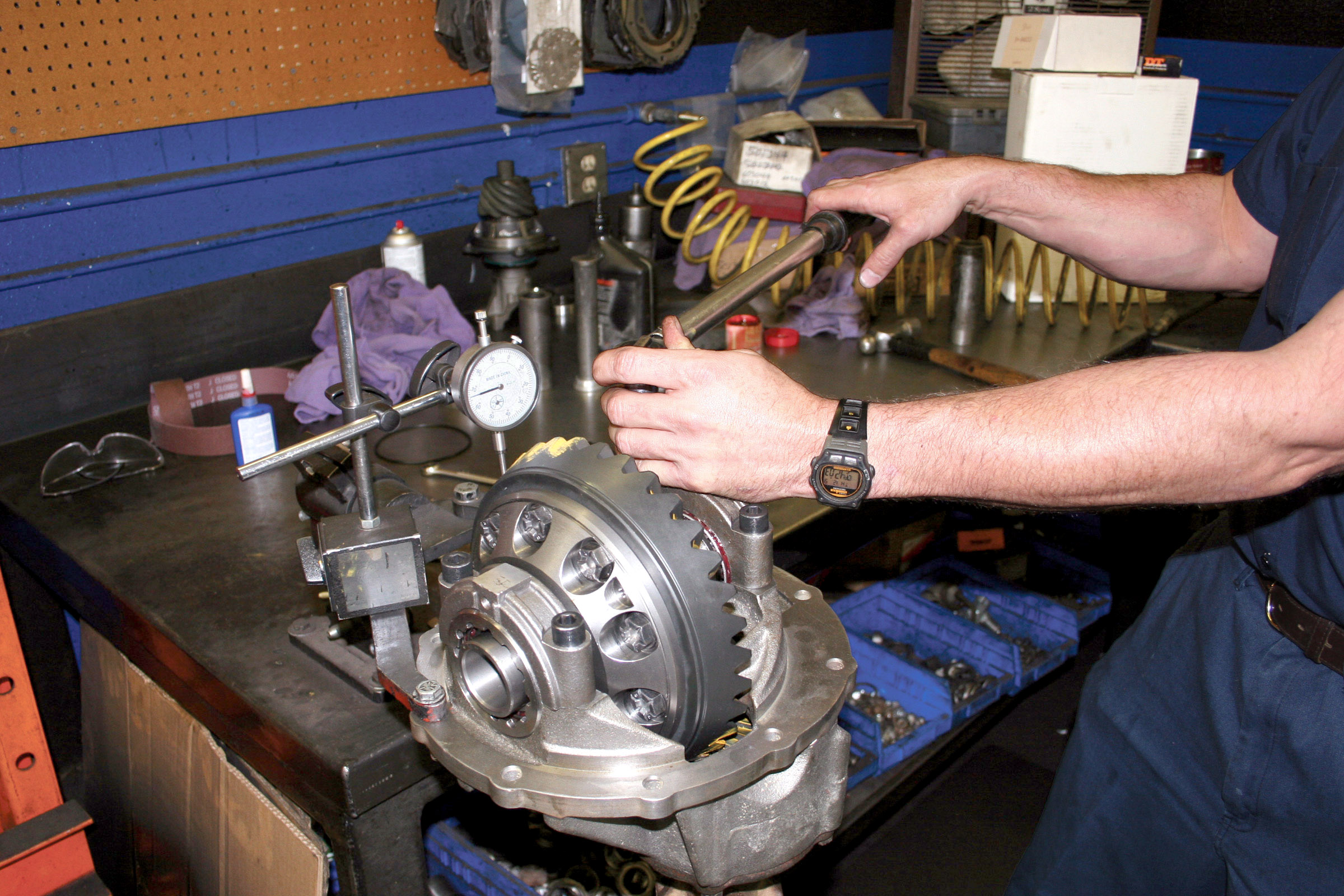
Enter Broncaroo–Steven’s 1973 Ford Bronco project. In this installment, Broncaroo benefits from a heavy helping of stronger axles and low rock-crawling gears from Superior Axle & Gear. Air lockers from ARB will fill both differentials, and it’s all expertly put together by Coast Driveline & Gear in Ventura, California.
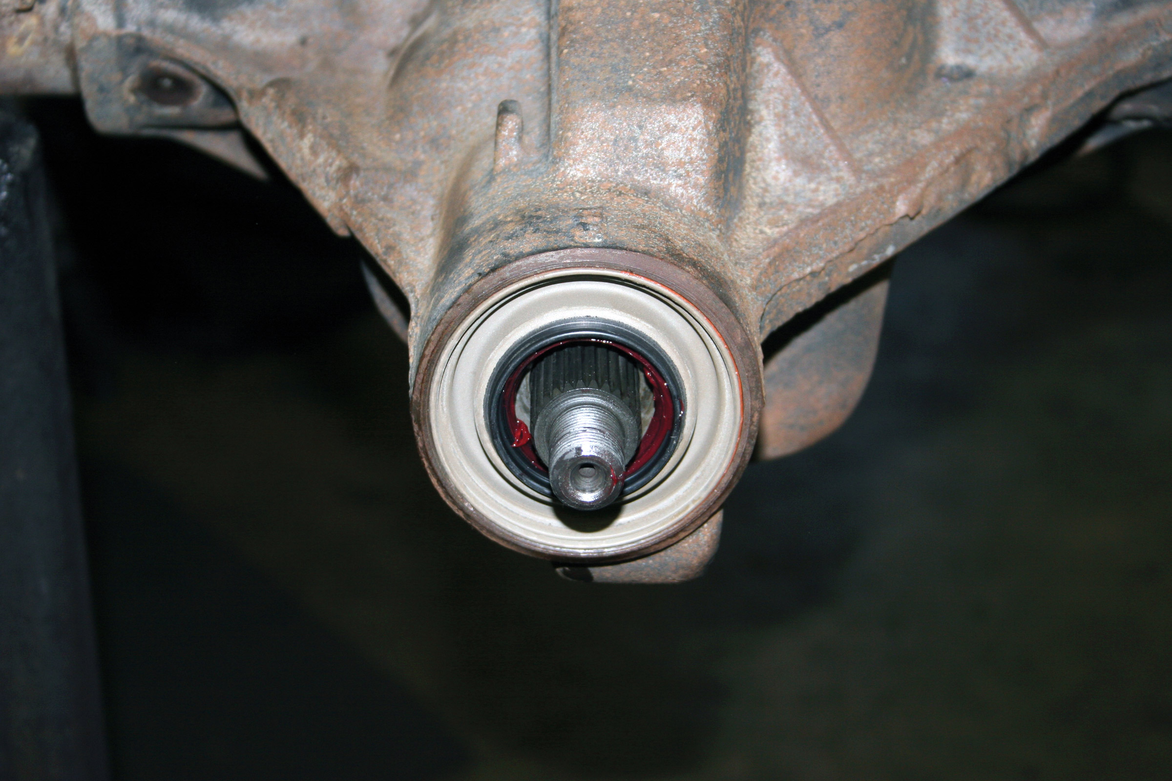
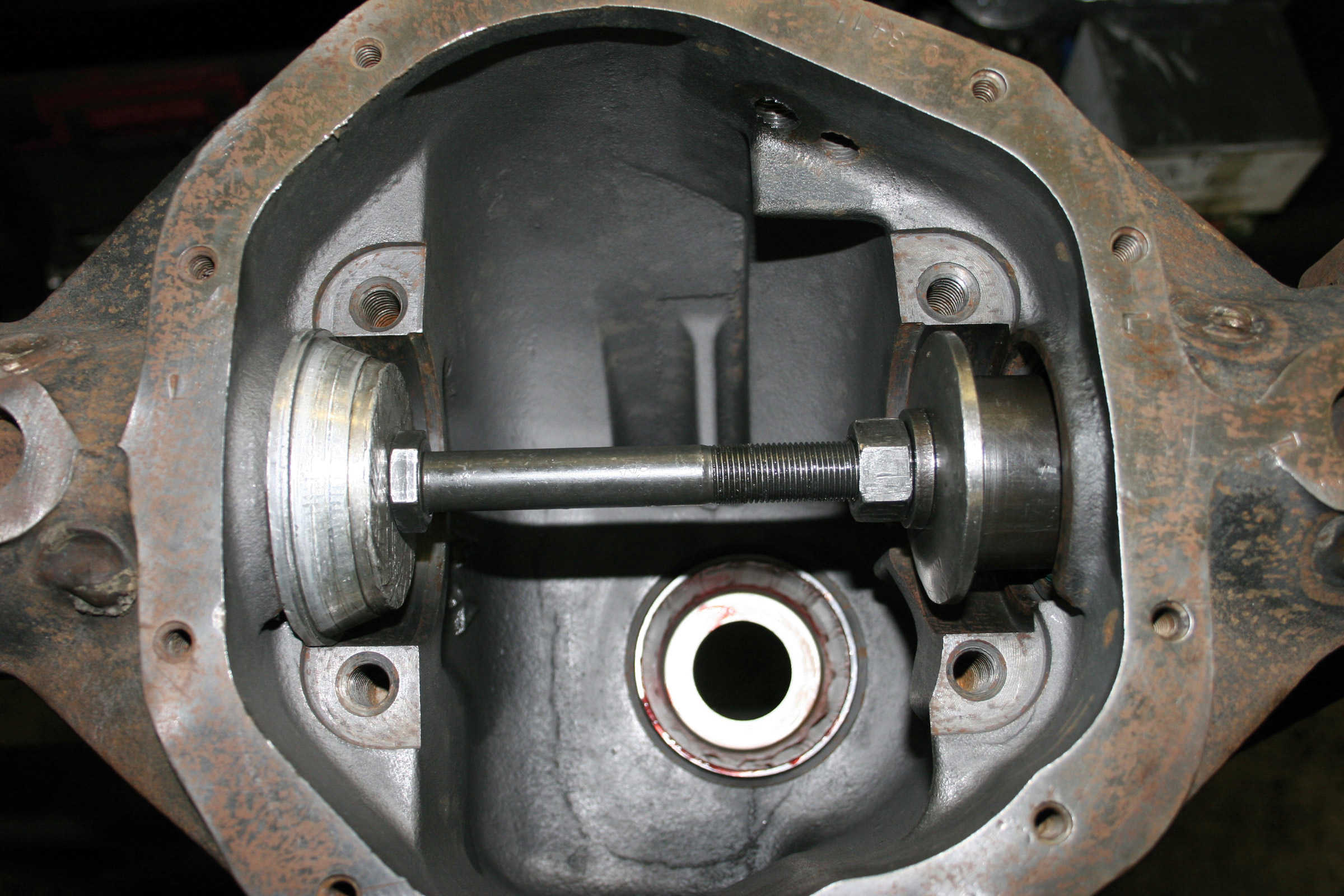
SHAFTED
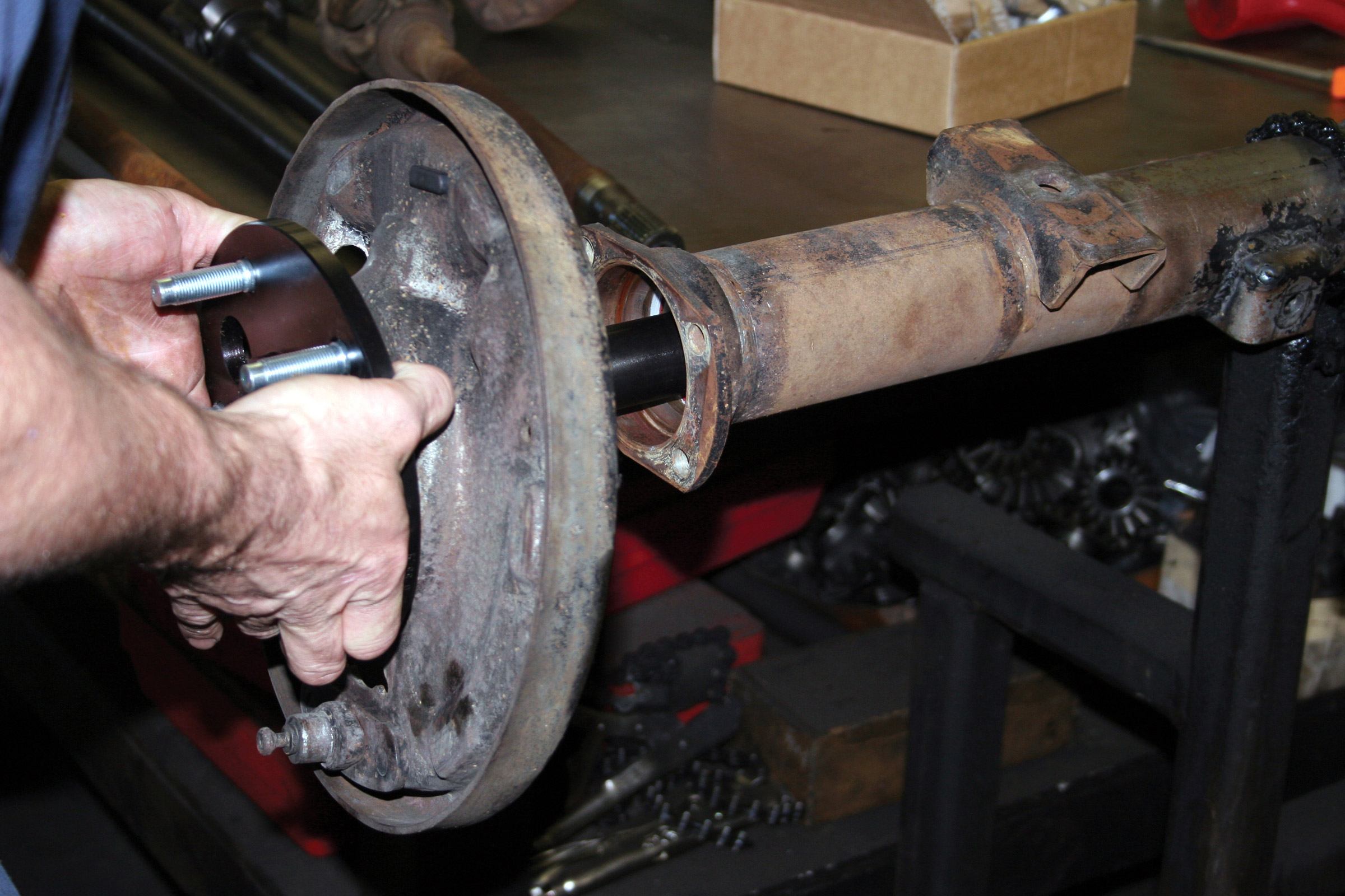
Axles have it tough! Think about it: They are caught between the engine’s torque, which has been multiplied many times by the transmission, transfer case reduction and low final-drive gearing, only to have forces on the opposite end doing their best to resist the rotation. The resistance efforts come from many factors when four-wheelin’. The most obvious is the 4×4’s massive tires. In Broncaroo’s case, 37×12.5×17 Trail Ready tires will be beat against VW-size boulders. It is not uncommon for an axle under full torque to be twisted 180 degrees. Of course, as soon as the throttle is closed or the tires break traction, the load is diminished and the axles untwist, only to repeat the routine seconds later when everything hooks up again.
This constant twist-and-release action will work-harden the material over time. Once they’re work-hardened, the axles will resist twisting, and will break. Eventually, this will happen to even the best axles, but the best can handle a lot more before reaching this point. Experienced four-wheelers who use their 4x4s hard know how long axles will live in their vehicle. The smart ones then replace those axles shortly before they fail. They are easier to replace in the garage than on the trail. Upgrading to high-quality, larger-diameter aftermarket axles also greatly reduces failure opportunity.
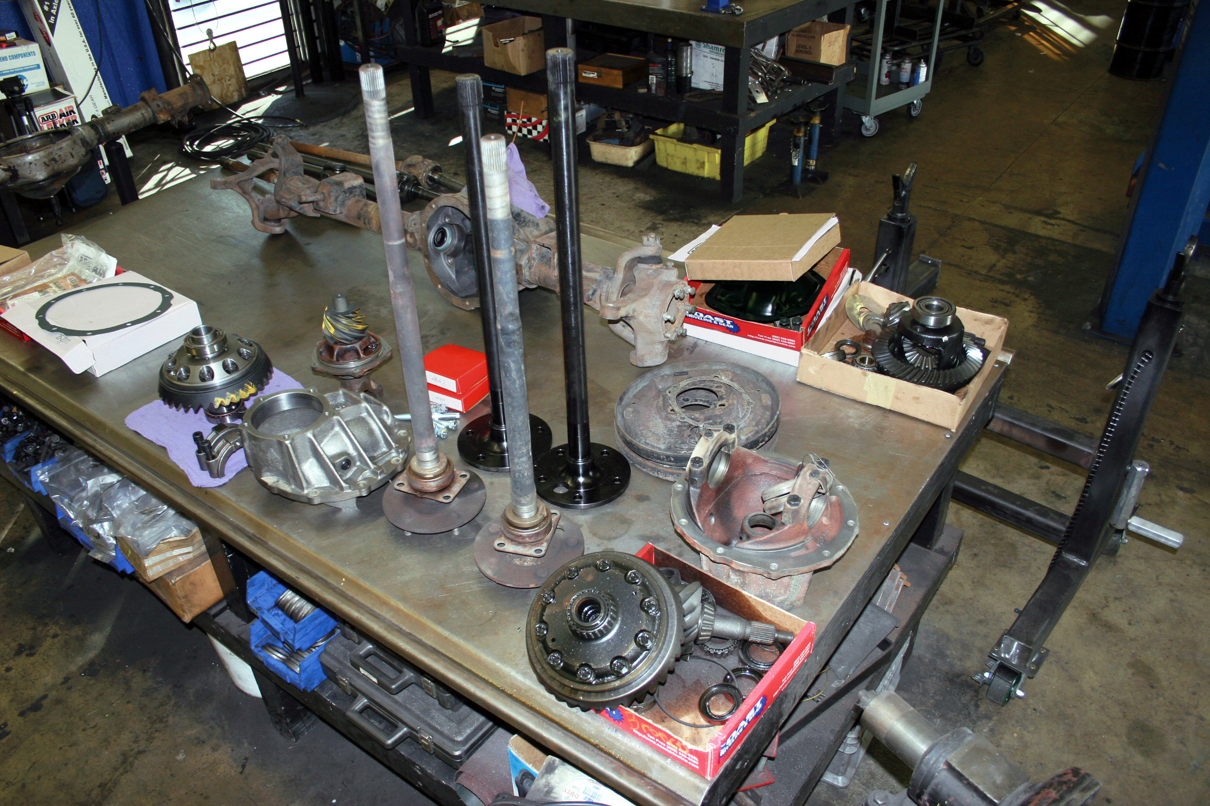
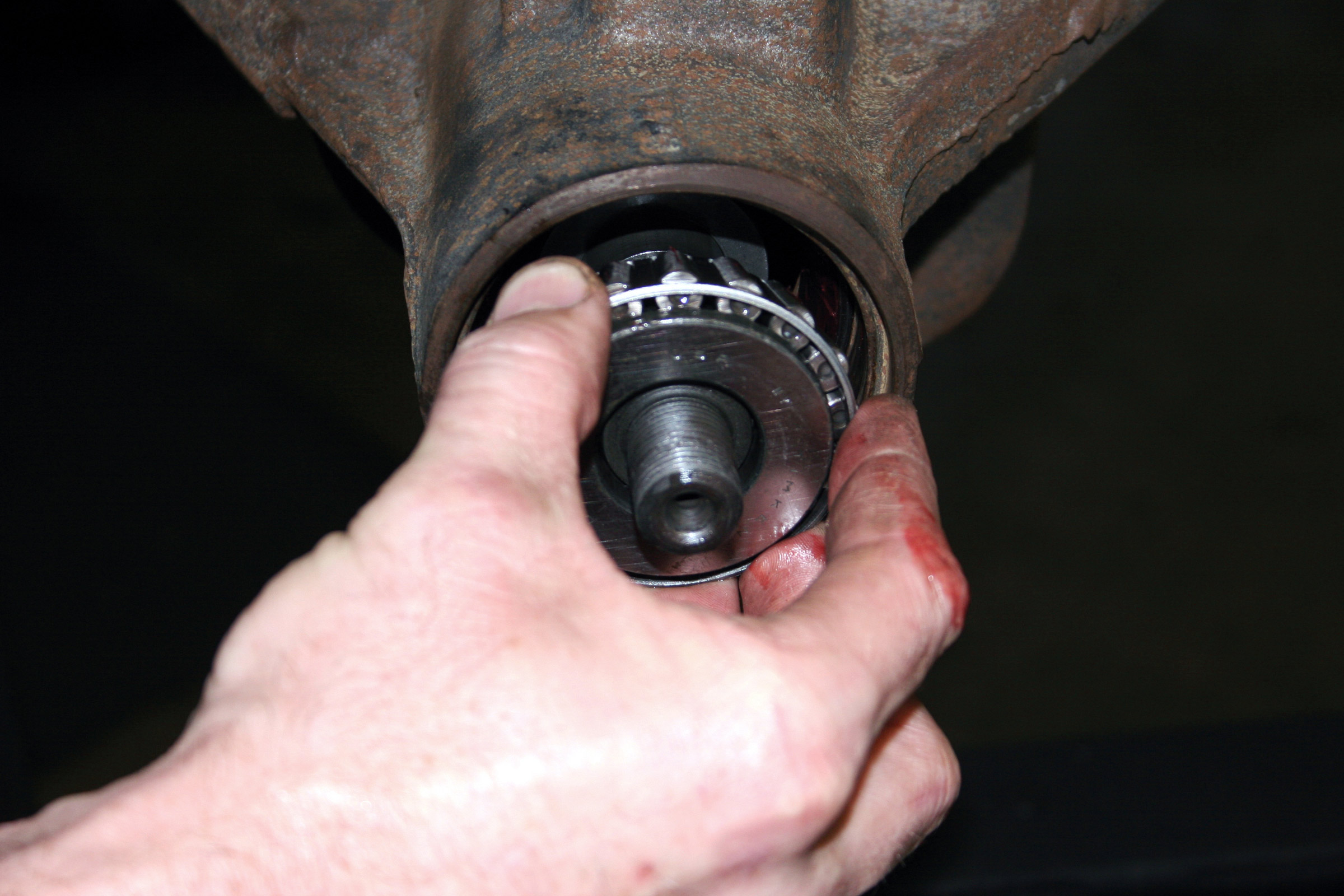
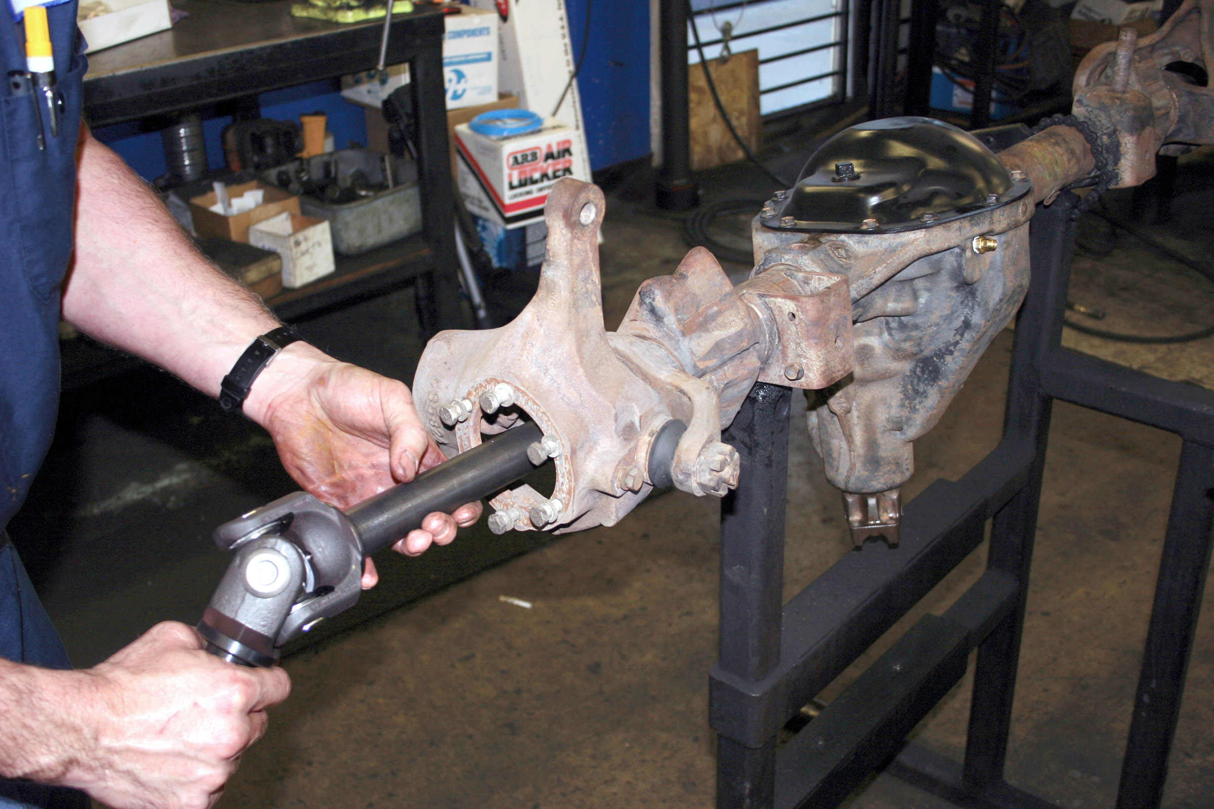
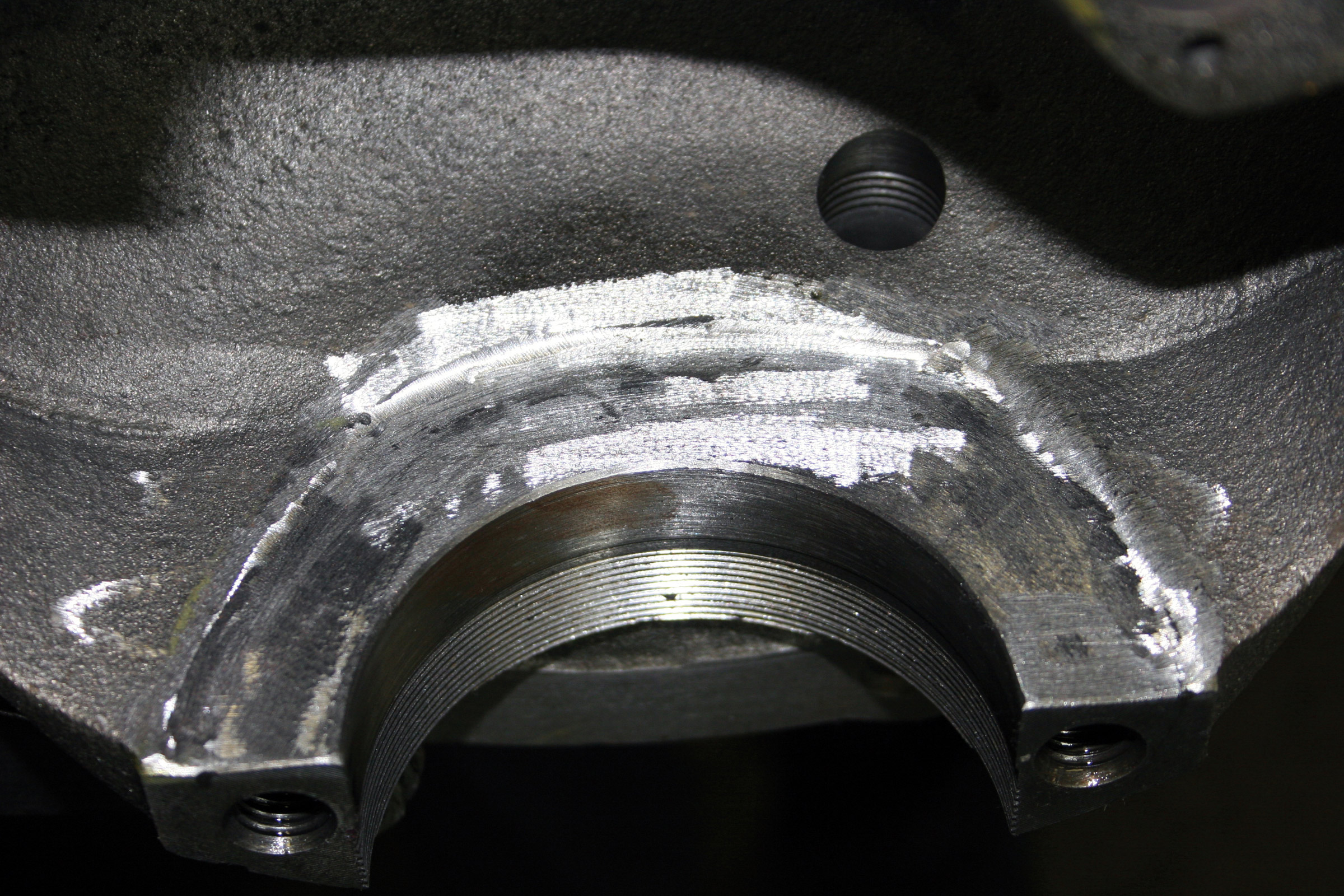
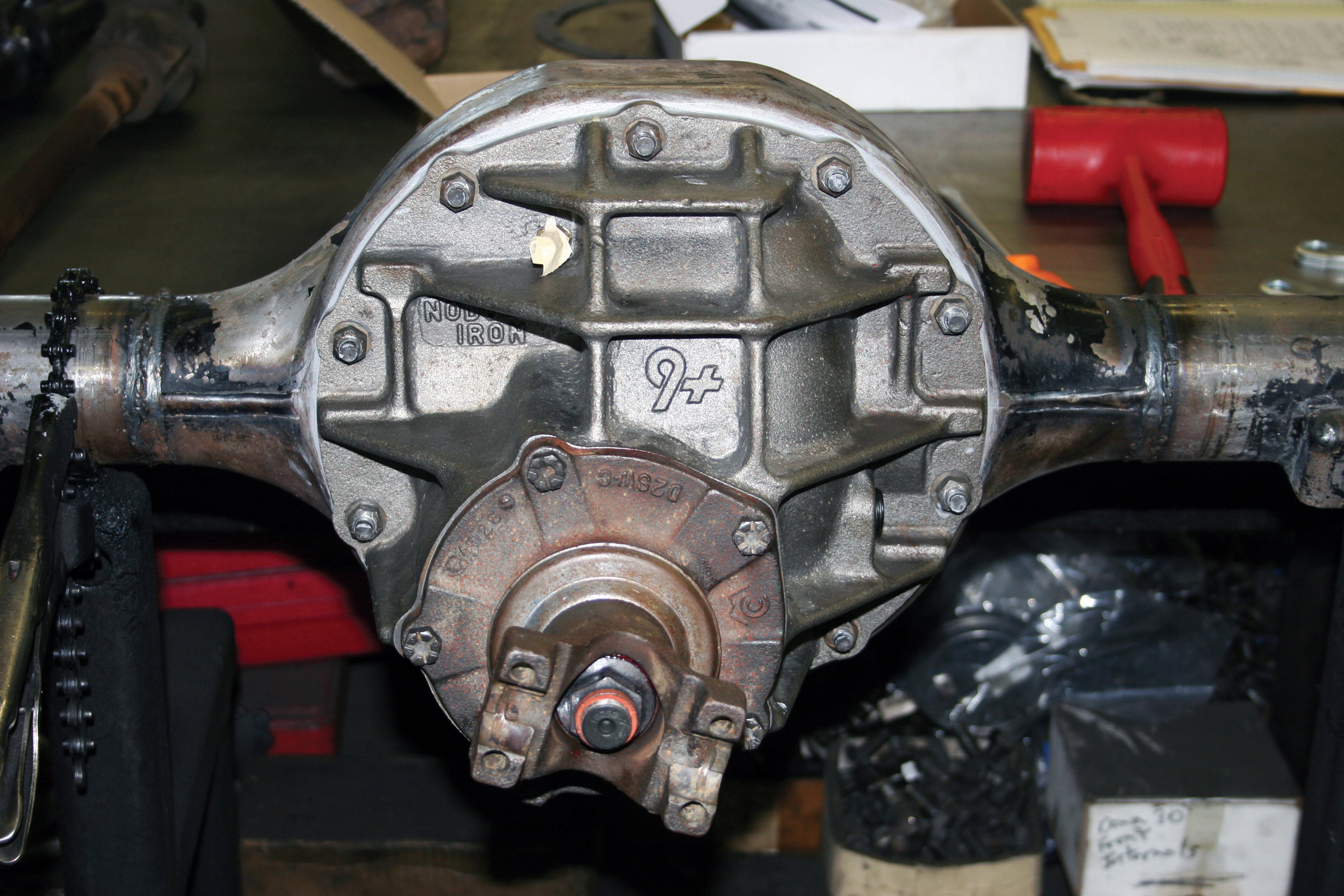
Though the ’73-vintage Bronco came with a front Dana 44 and a Ford 9-inch rear, favorites of many four-wheelers, that doesn’t mean they cannot be improved. In fact, because they are so popular, there’s a lot of great products available to improve them further.
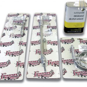
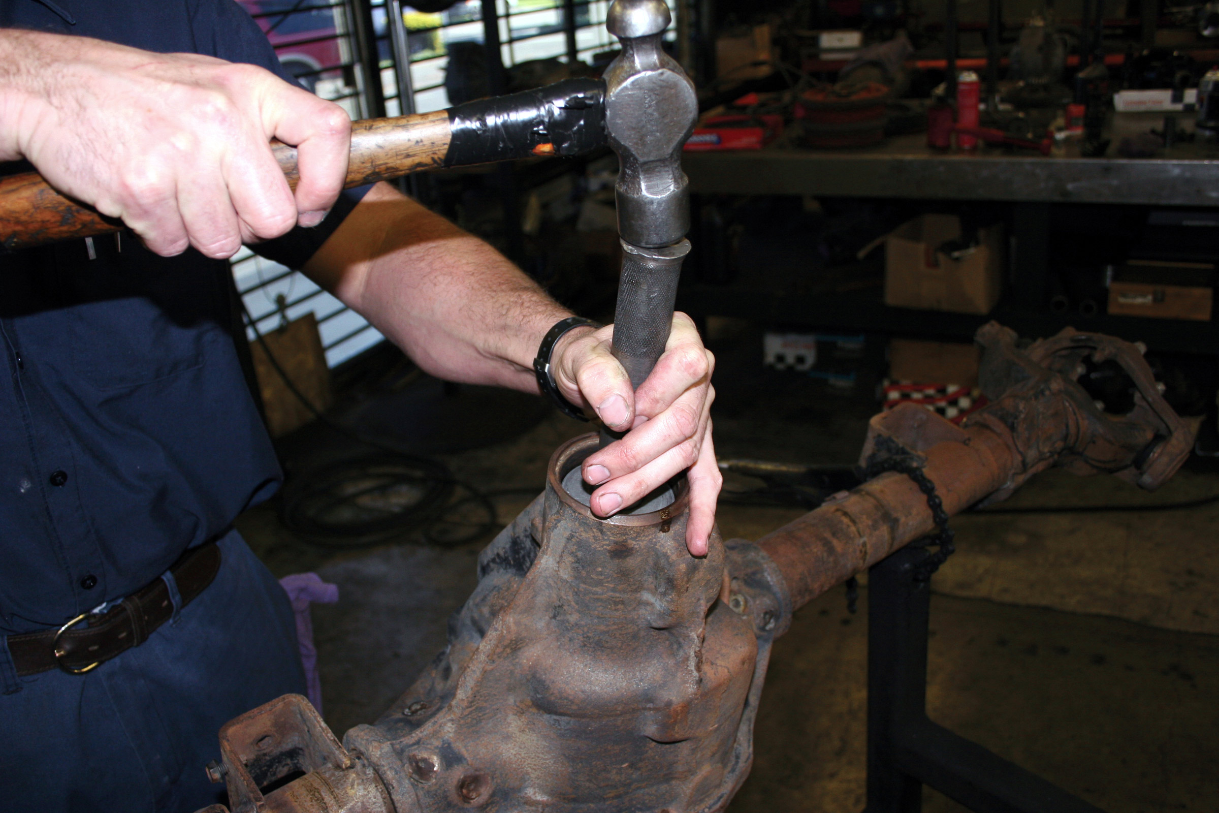
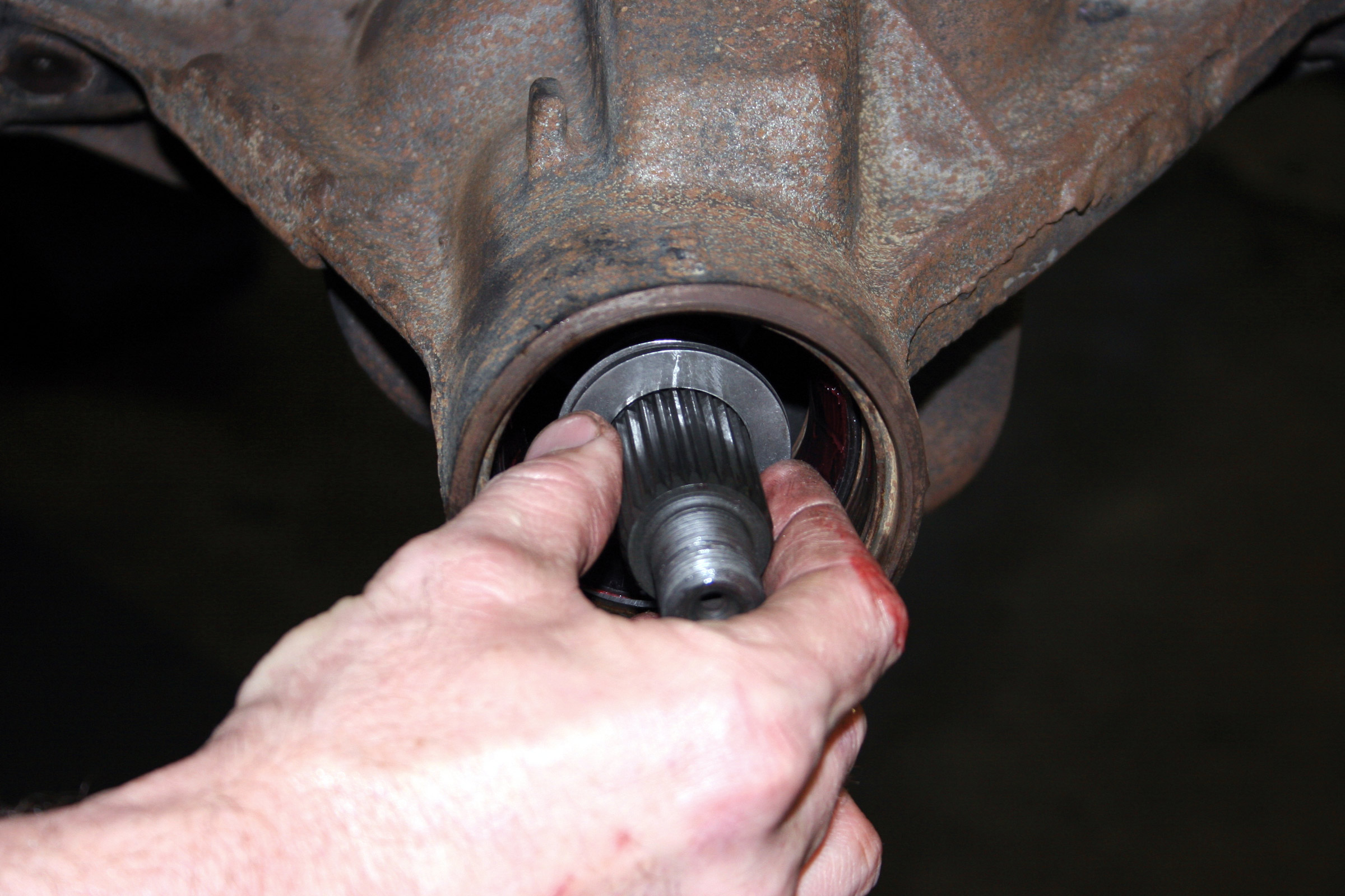
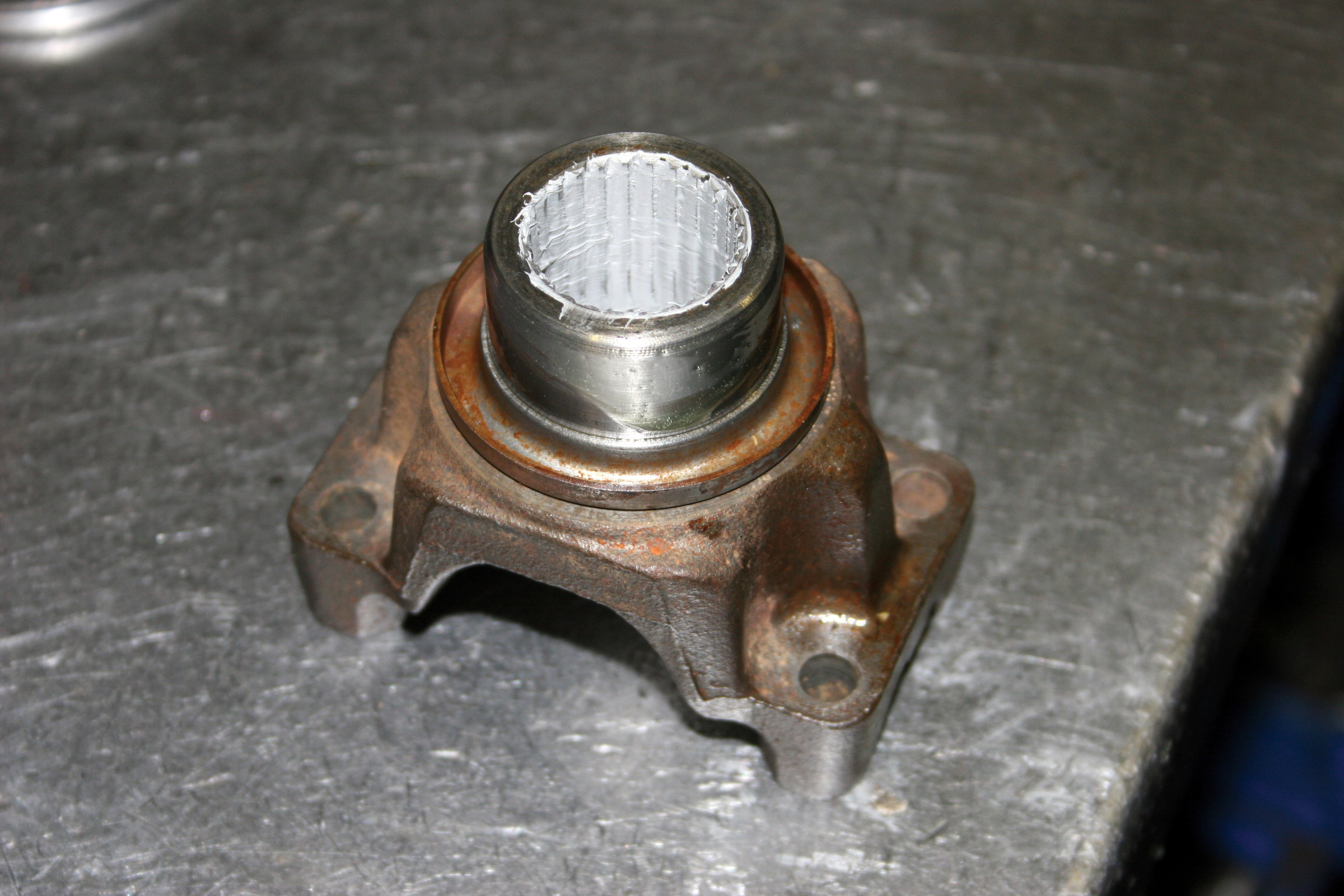
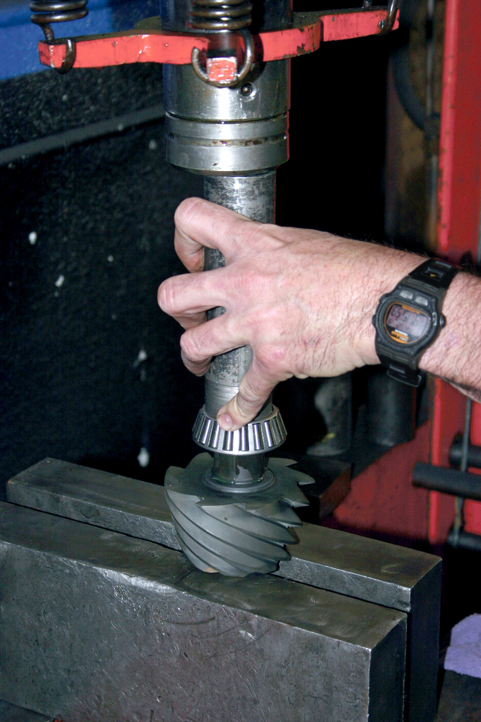
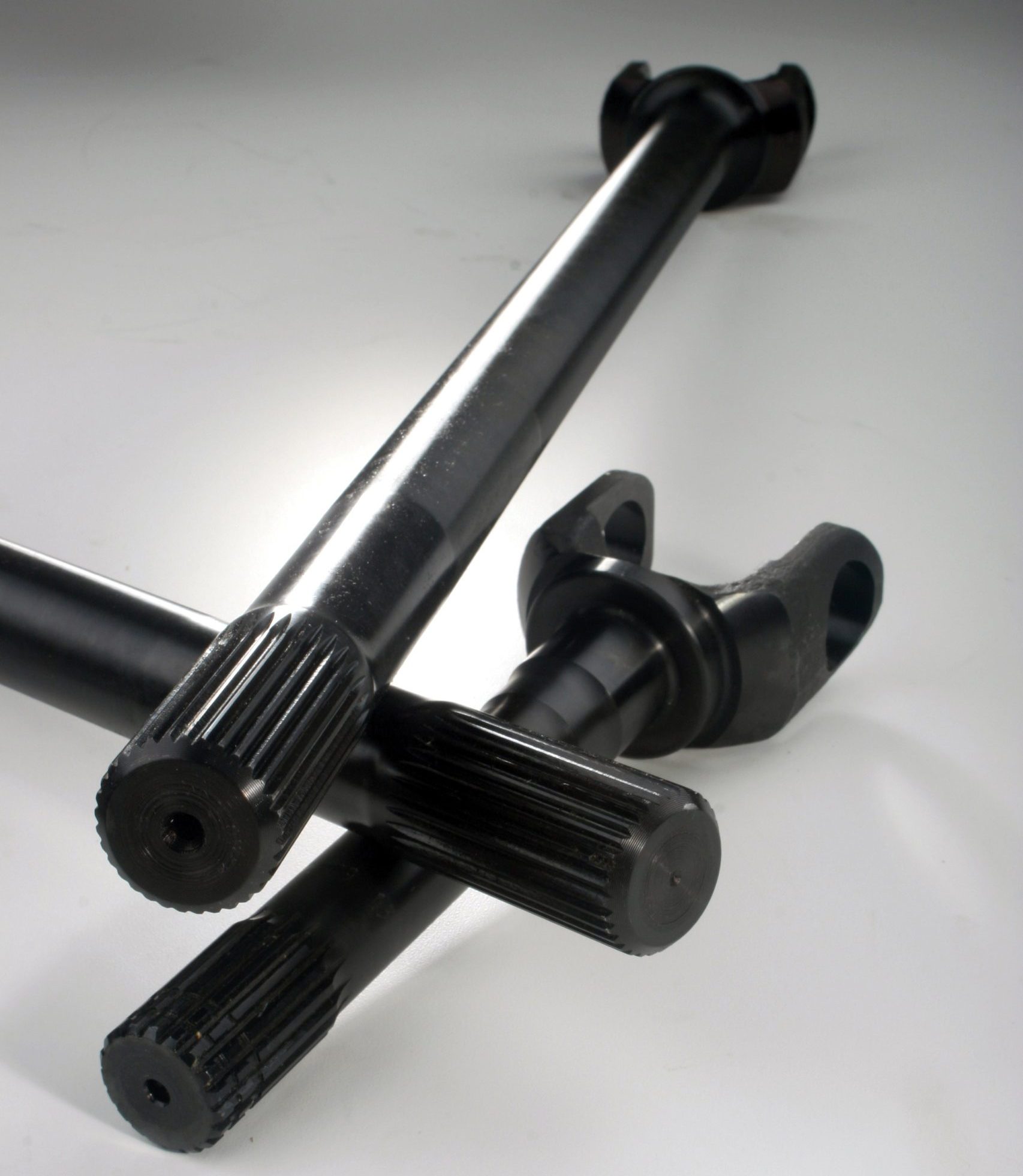
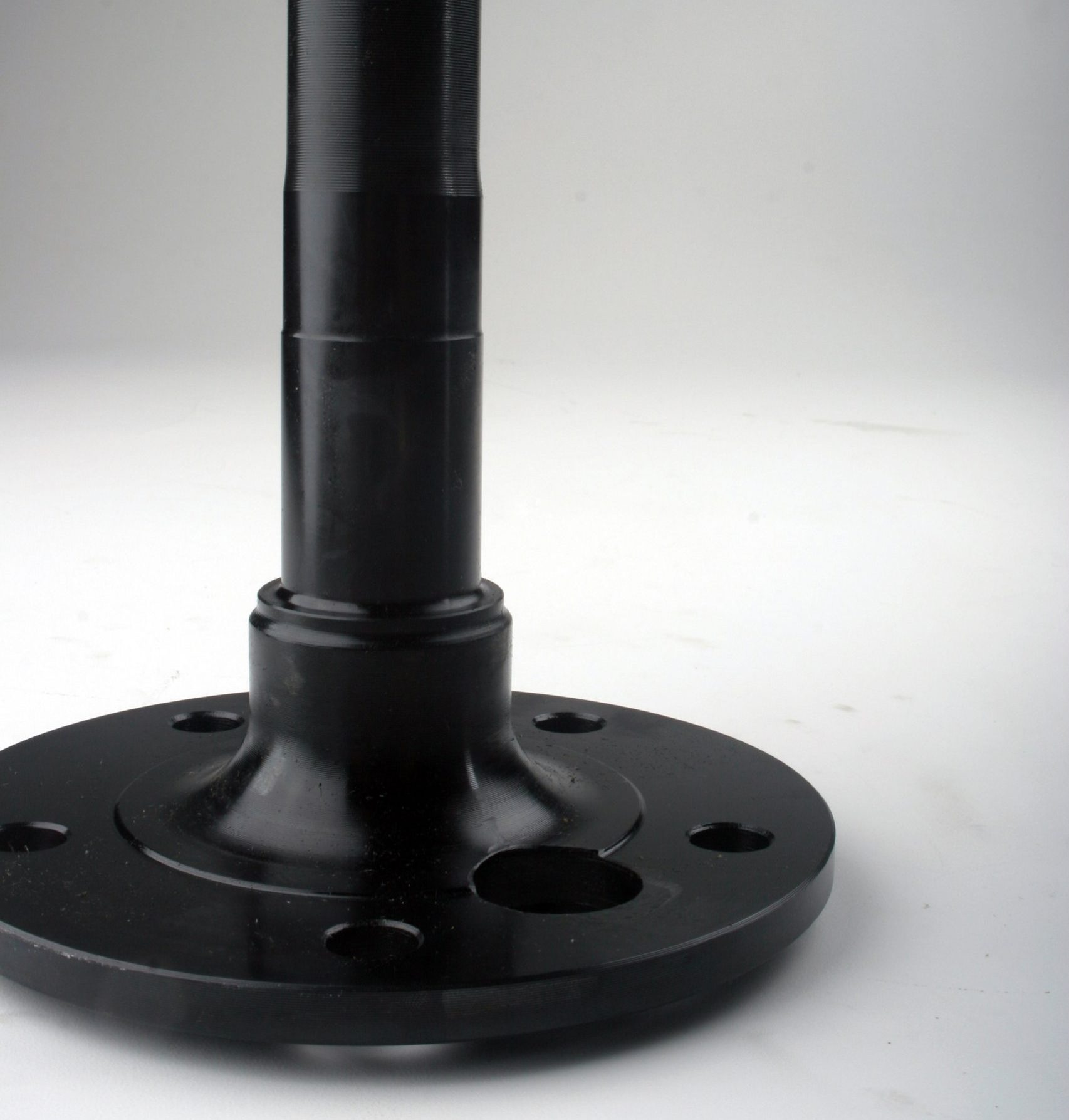
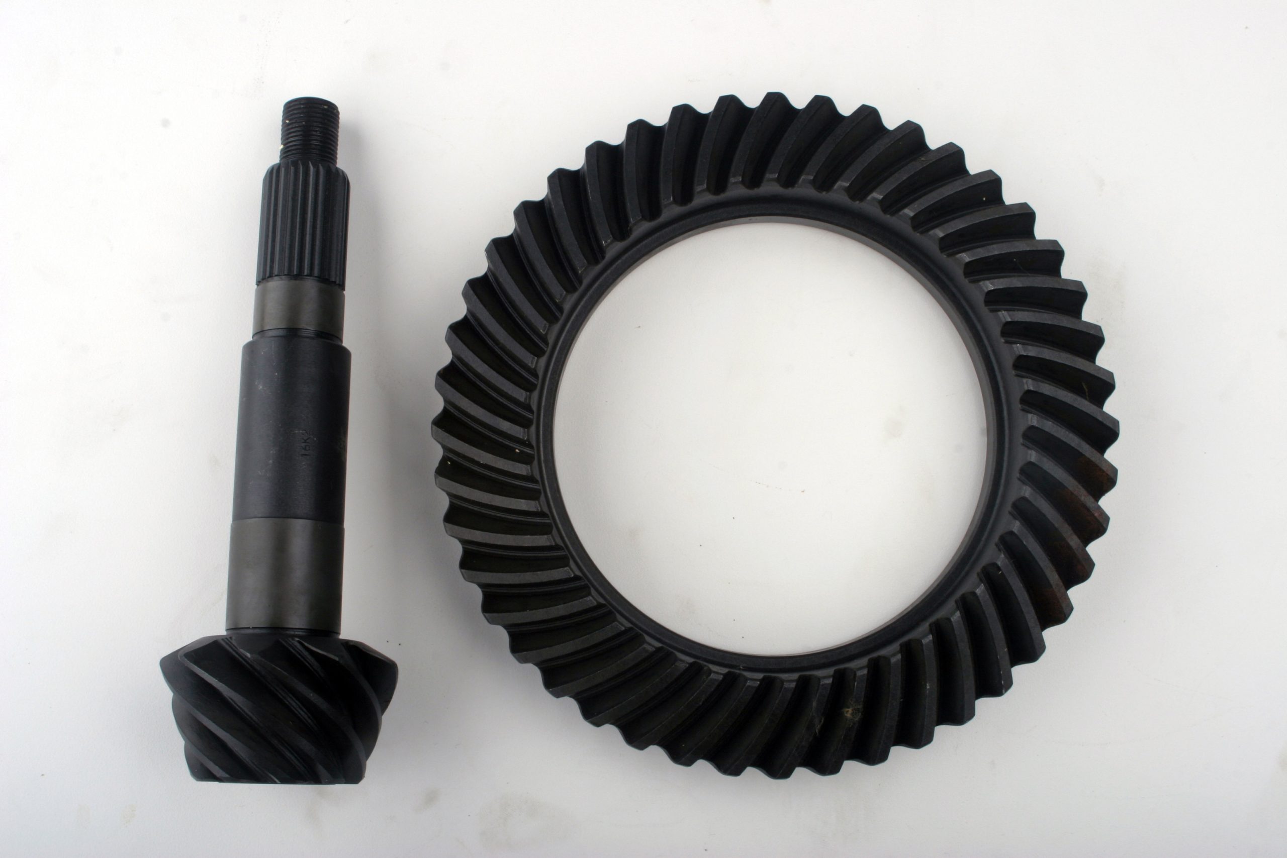
Here Steven turned to Superior Axle & Gear. It is among the largest axle manufacturers. It has OEM replacement axles as well as custom shafts with larger diameters, more splines, different bolt circles, and so on.
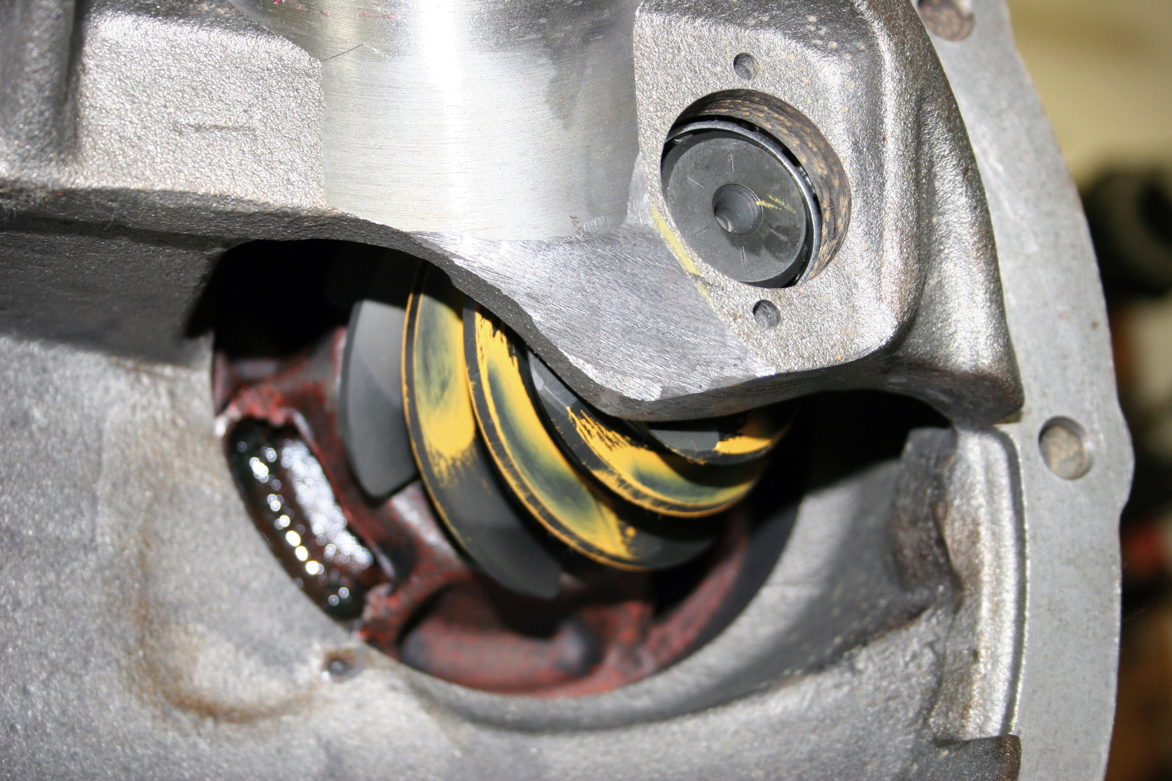
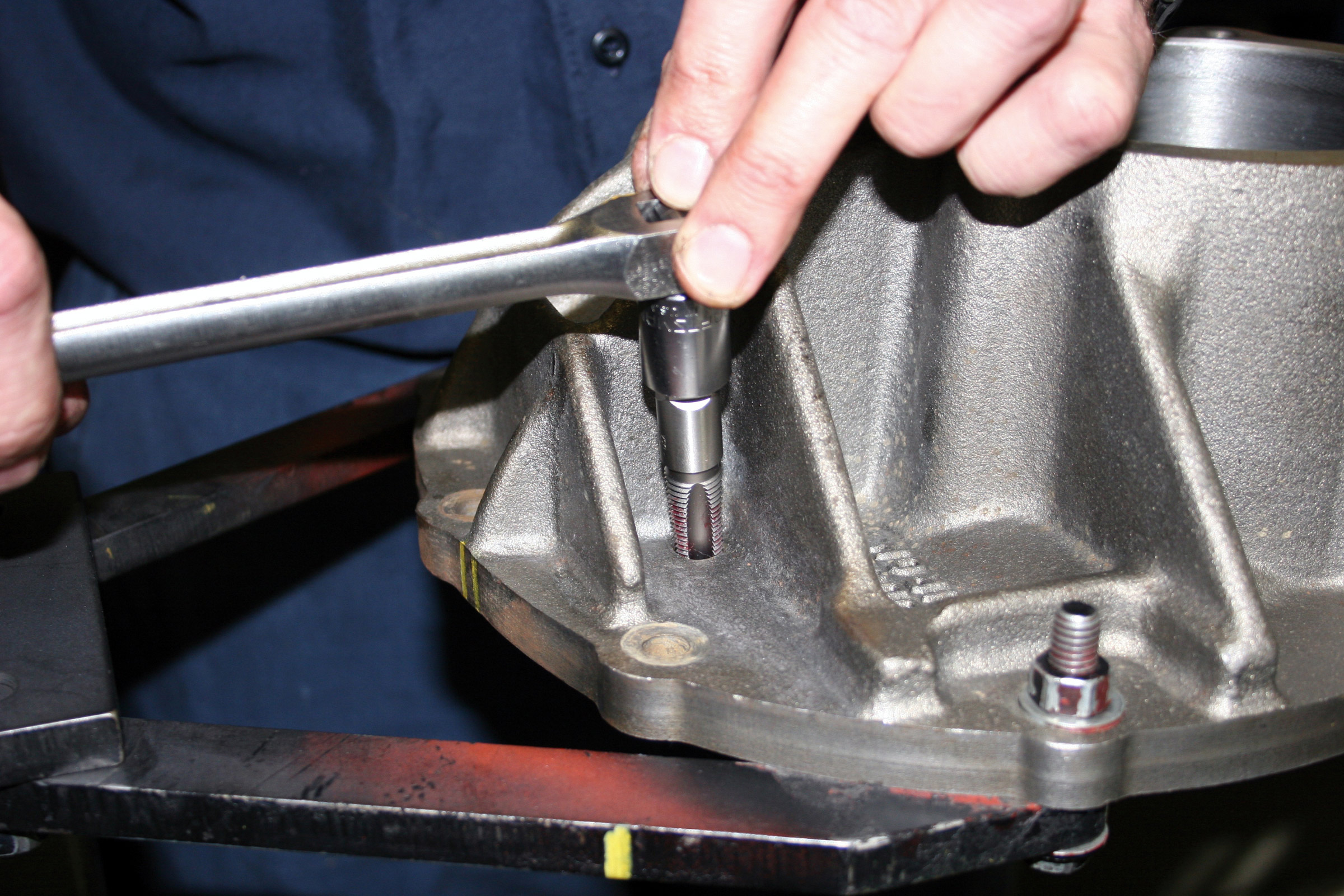
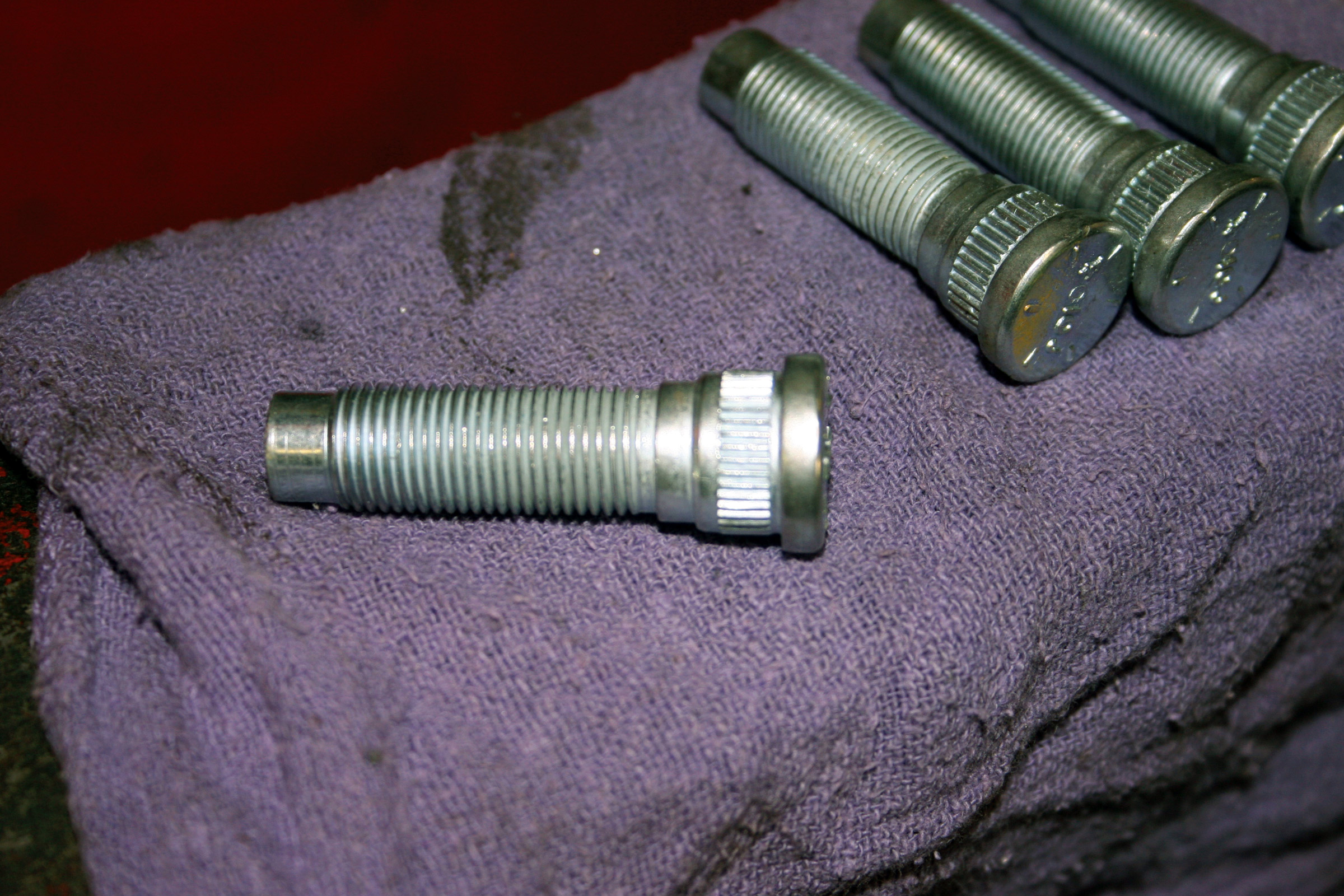
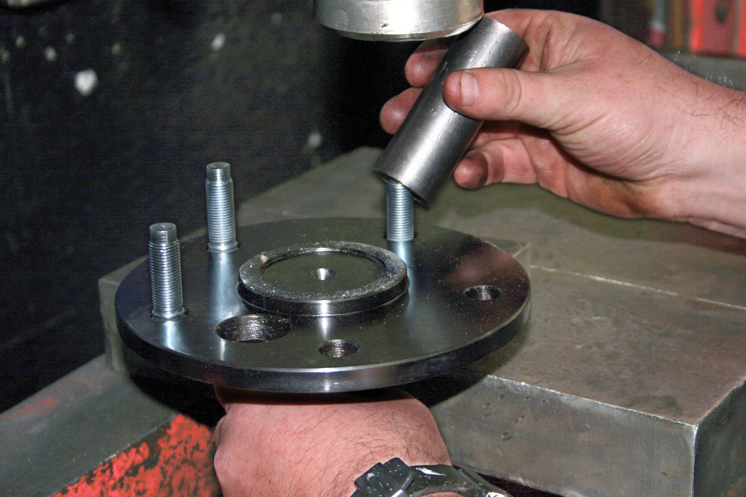
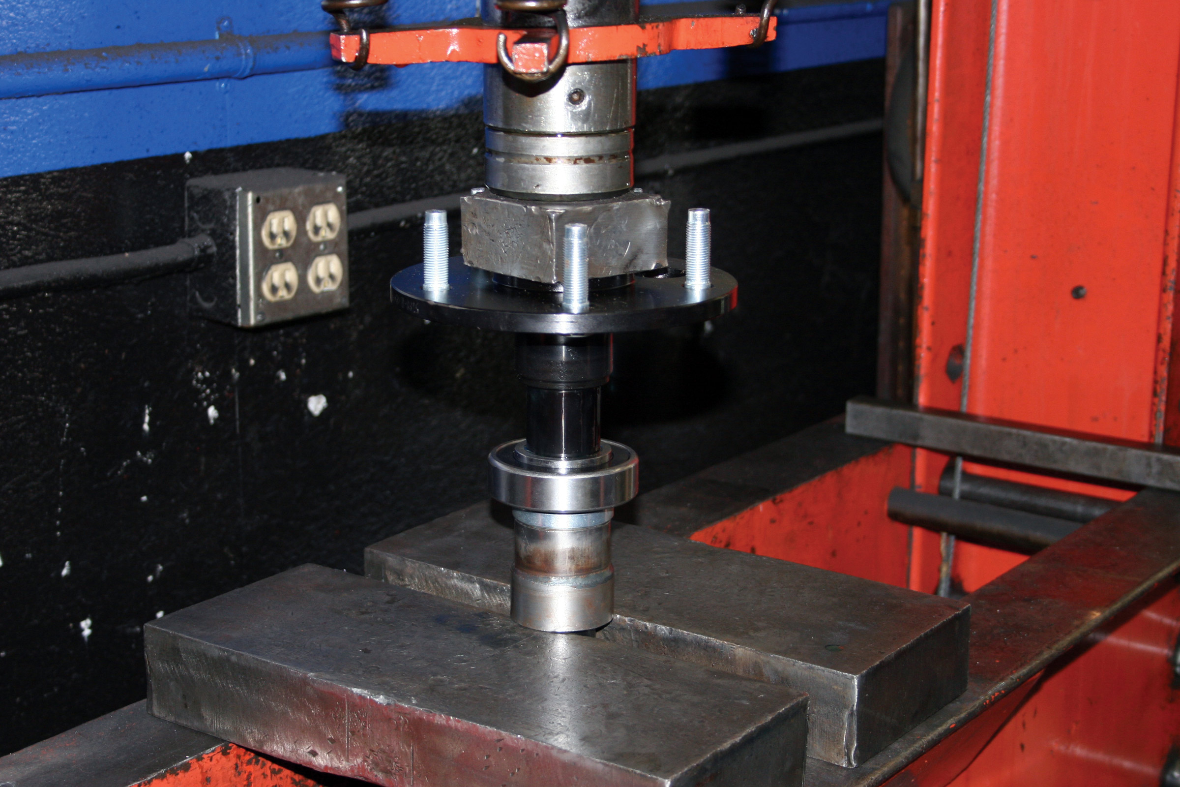
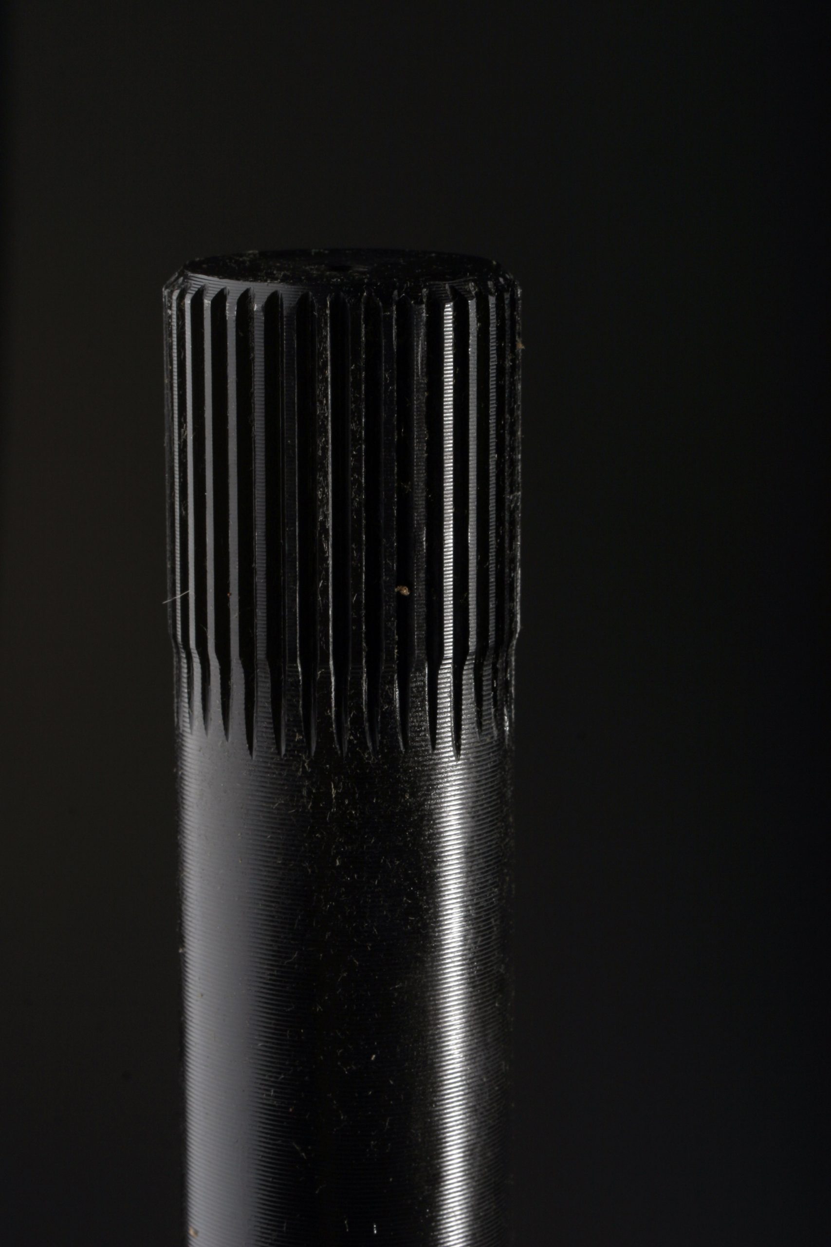
Superior’s axles are first forged and then machined, splined and heat-treated. Wrought in this fashion, the spline can be rolled on, a cold-form process in which the splines are formed under tons of pressure. Cold forming is said to produce superior grain structure as well as involute splines, which are the correct shape for factory side gears. The axle is then heat treated, resulting in much stronger splines compared to those that are cut.
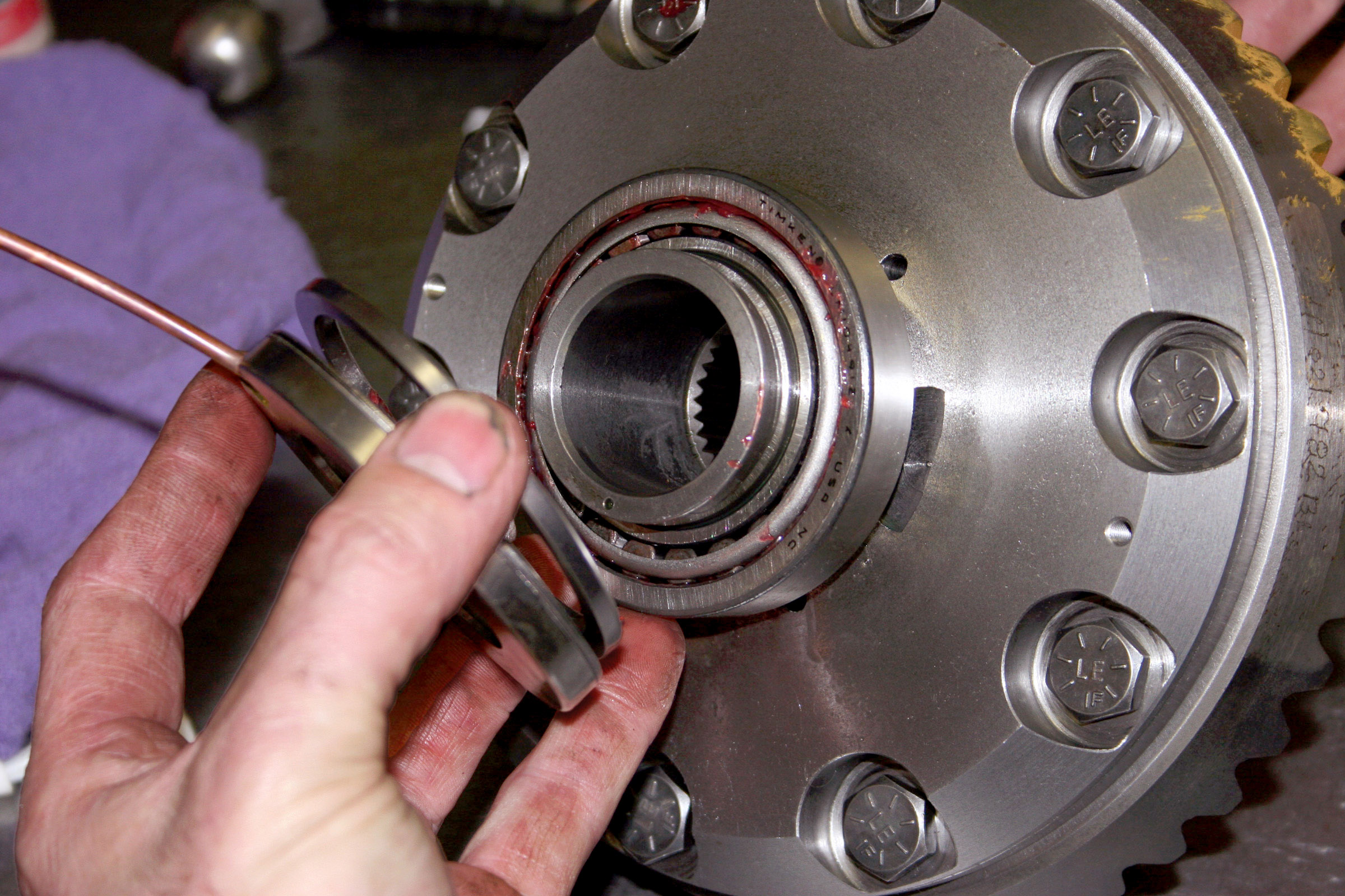
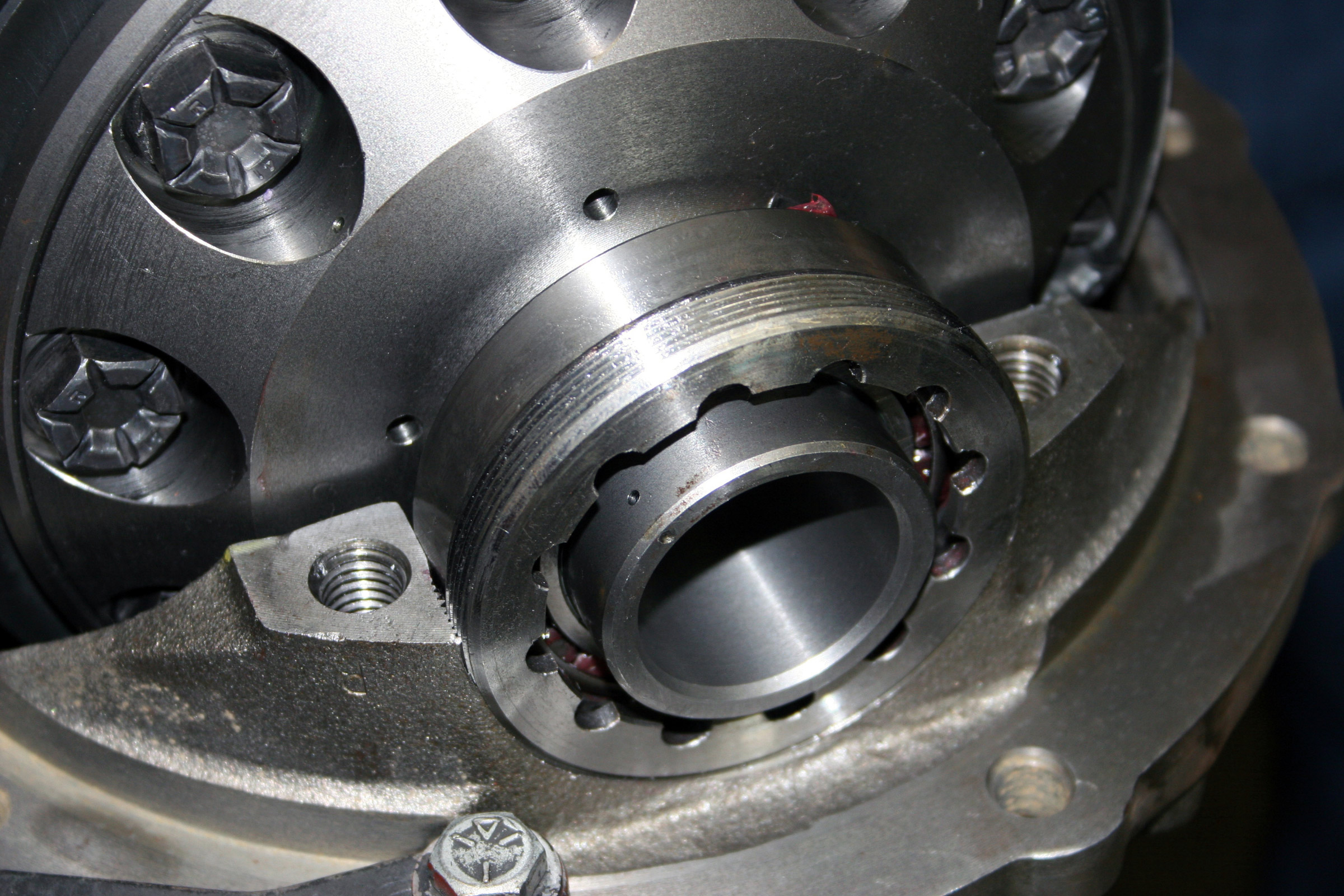
LOCKED UP
Most first-generation Broncos, or any 4x4s for that matter, came with open differentials; a few were equipped with limited-slip diffs from the factory, while still fewer were found with OEM locking differentials of any style. So what’s an open differential? For street use, it is arguably the best style of differential to have.
The reason is because roads are not perfectly straight, and at some point in time you do need to turn. During a turn, the inside tire travels a shorter distance than does the tire across the axle on the outside of the turn. Since the outside tire swings a larger arc, it traverses a greater distance. To do so, the tire on the outside must rotate faster and a greater number times than the inside tire.
In the simplest of terms, through a series of internal gears, an open differential is designed to allow each wheel to turn independently, thus eliminating binding during cornering. This is ideal for use on pavement where smooth operation and long tire life, among other factors, are paramount.
Off-road, however, open diffs are not such a hot deal. When one tire loses traction, an open differential effectively directs all the engine torque to the spinning tire, rather than to the tire with traction, so momentum is lost. The clearest example of this is the two-wheel-drive vehicle that pulls off the shoulder of the road with the right-side tires in deep sand and the left-side tires firmly on asphalt. You’ve been there–the tires in the sand spin and bury themselves, while the ones on pavement do nothing. The vehicle does not move and is stuck. Obviously, the open differential is not the ideal type to use when venturing off-road.
The next differential up the off-road food chain is the limited slip .Limited-slip differentials use various mechanisms to allow open-differential-type action when going around turns; yet if a tire begins to spin, a limited-slip differential transfers more torque to the non-slipping tire. The most common limited slip accomplishes the torque transfer via spring pressure and clutches within the differential.
The king of the off-road hill is the locking differential, or lockers, as they are commonly called. Lockers work great off-road and can be installed in either the front or rear differential, or in both. They essentially lock both wheels of the same axle together so that engine torque is divided evenly at nearly all times. Climbing ability is improved amazingly. However, a locker will release one wheel when turning on high-traction surfaces, such as pavement, and act momentarily as an open differential. Depending on the locker and how it is set up, turning can be jerky and can heavily load all the axle components. If a locker is used at the front, steering can be heavy. However, these steering characteristics are not an issue in the dirt, where there is limited traction and slippage occurs. It is generally agreed that if you are going to install just one locker, it should be in the rear to gain the biggest off-road advantage, but some people who use their 4x4s often on the road prefer to place the locker in the front diff. Why? On pavement, the 4×4 will be in two-wheel drive, with the front hubs unlocked, so the locker will not affect ride or steering. If it were in the rear, it would. However, there are many rear lockers on the street, and one becomes accustomed to driving with them and having the inside tire chirp a bit.
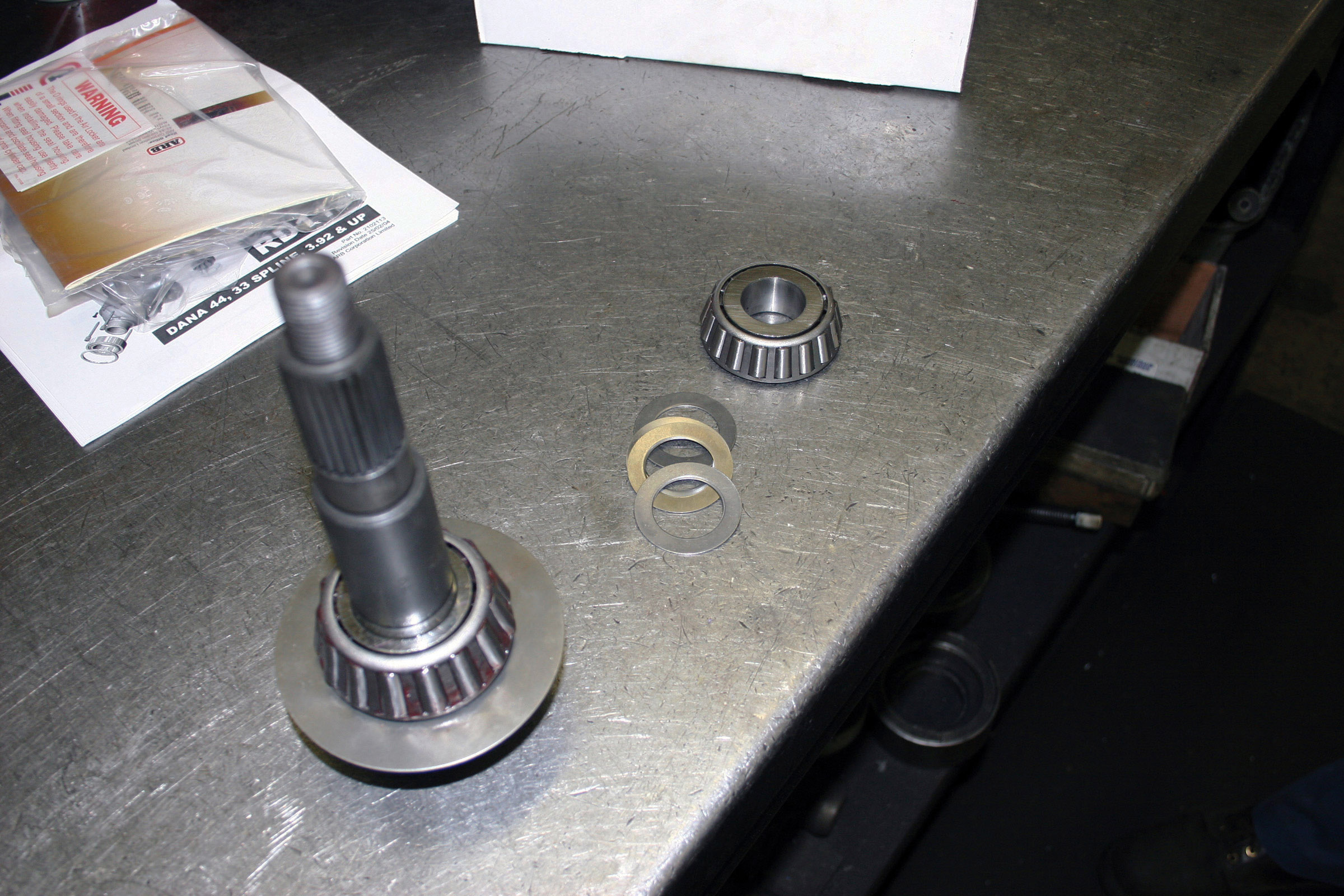
There are two remaining differential types: spools and selectable lockers, the most common of which is the ARB air locker. Spools are popular in drag racing, where there is no turning and strength is at a premium. They are simply a solid piece of splined steel to accept the axles and join them as one. They do not have any differential properties.
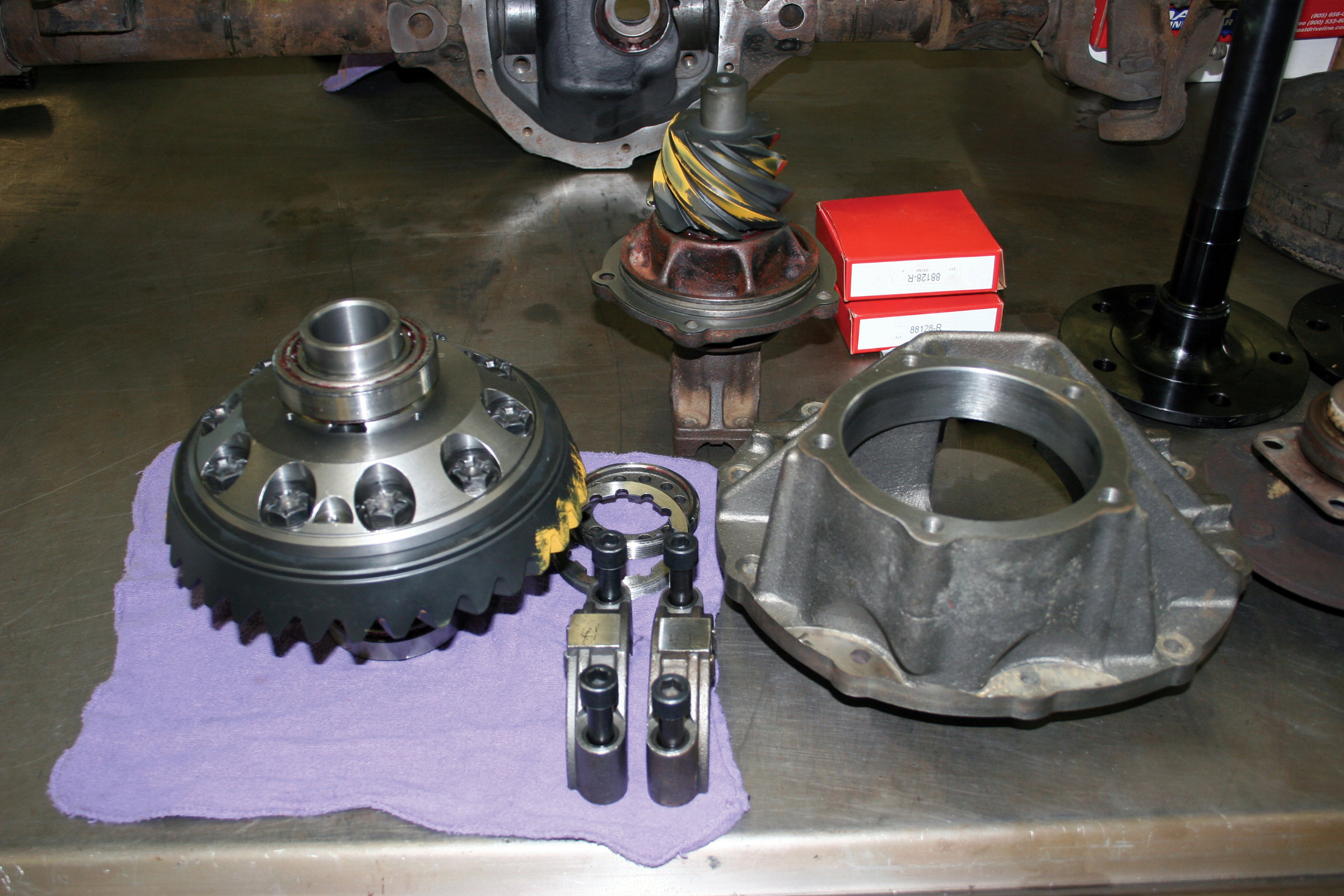
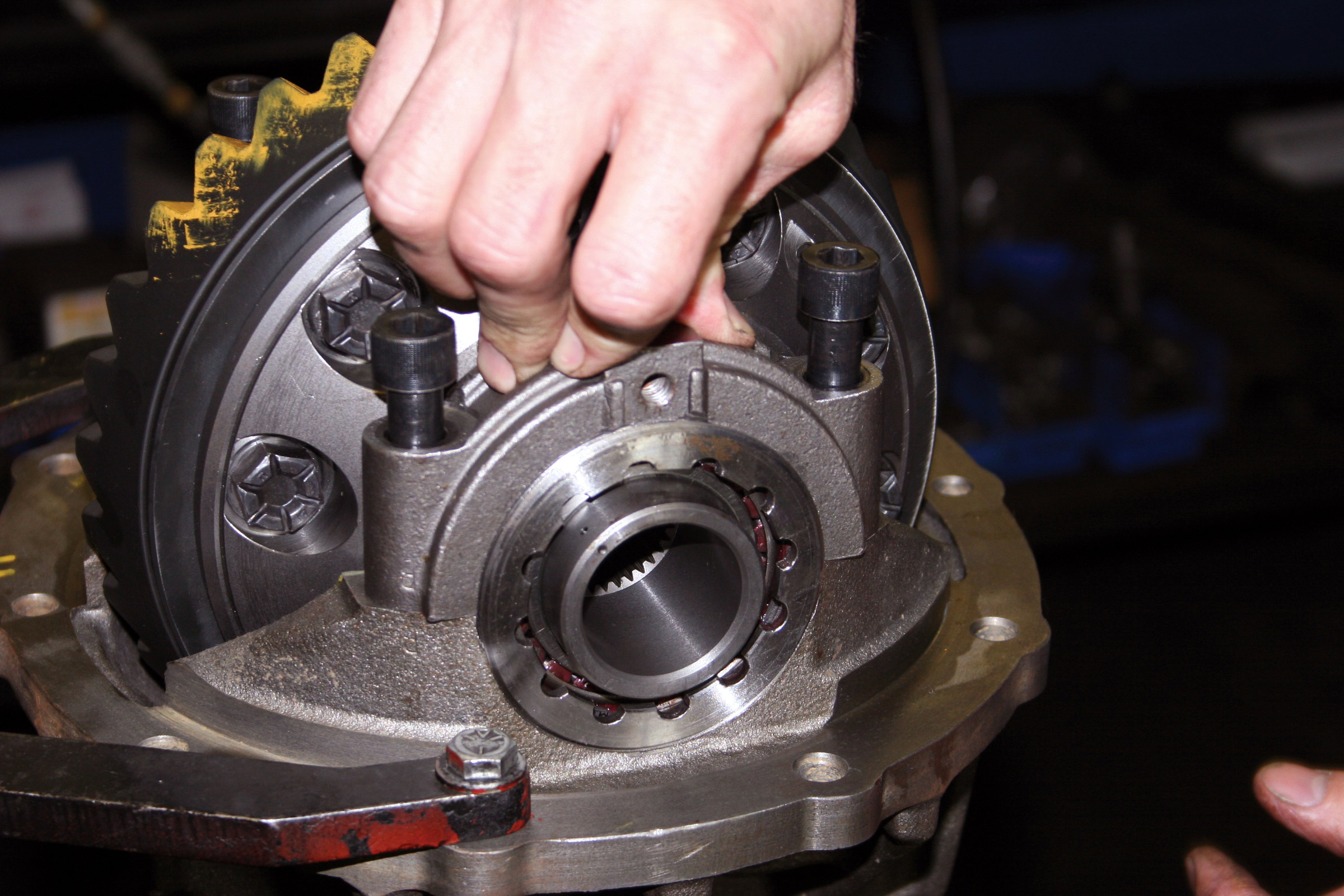
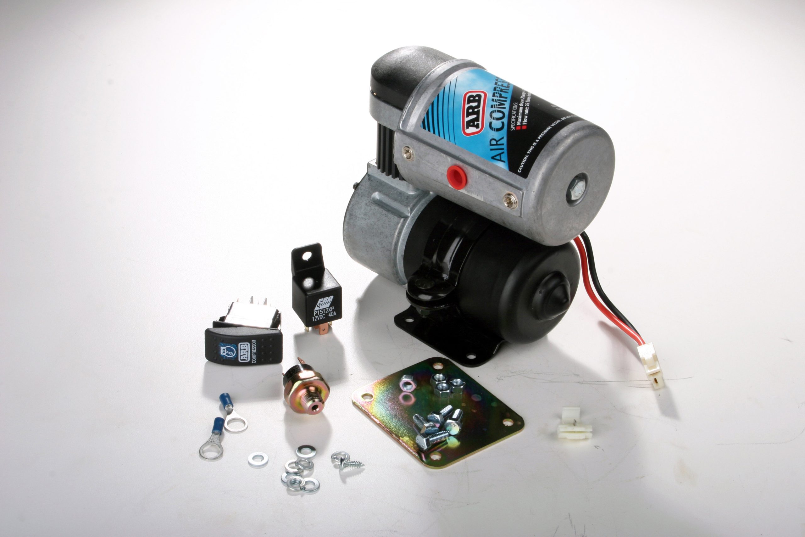
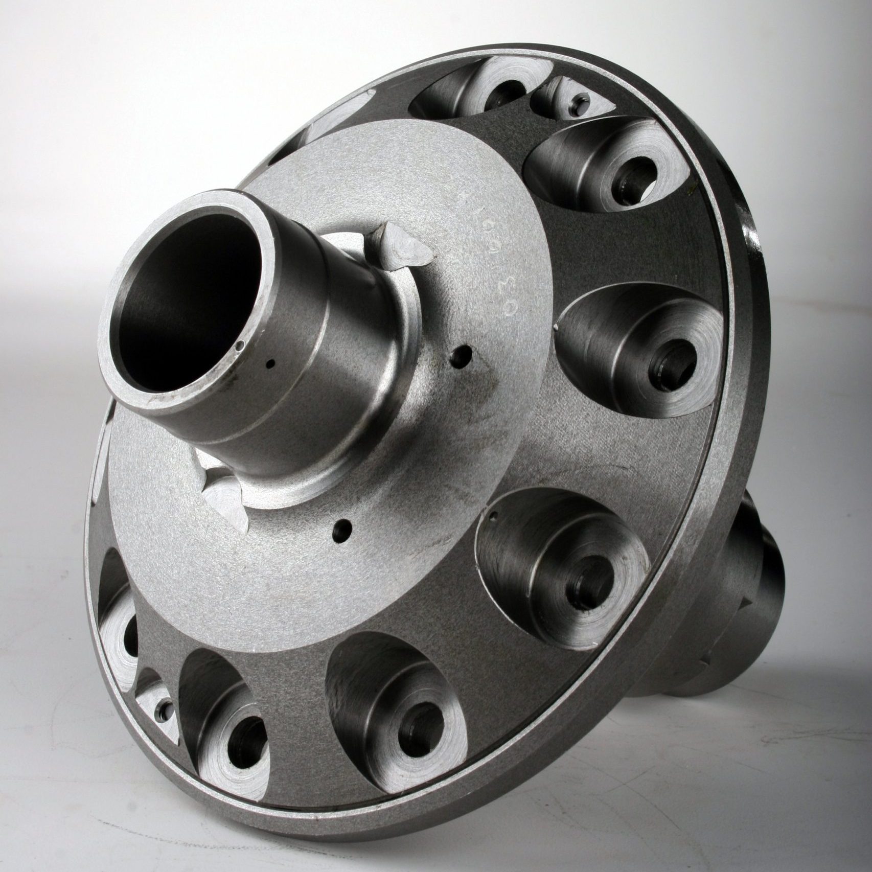
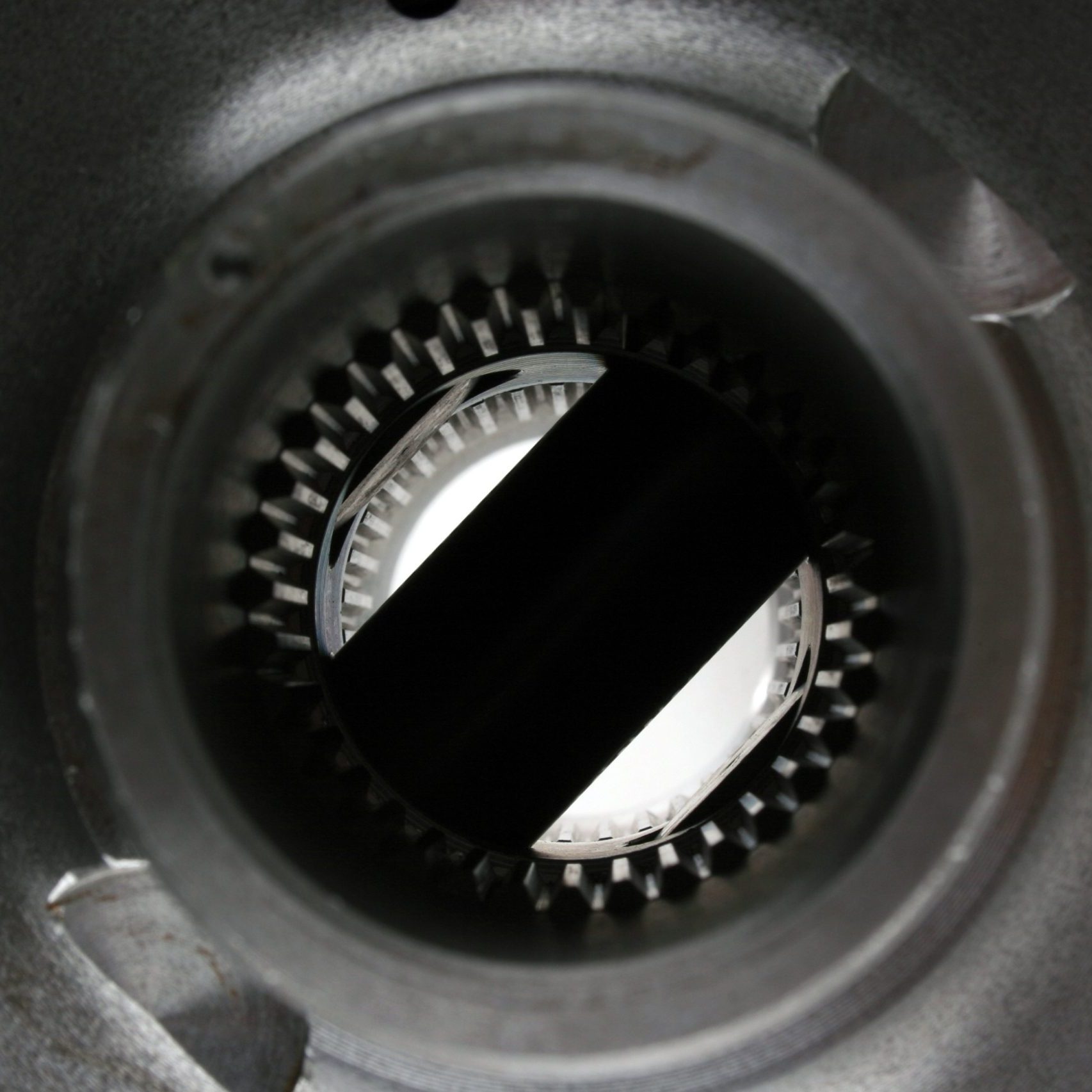
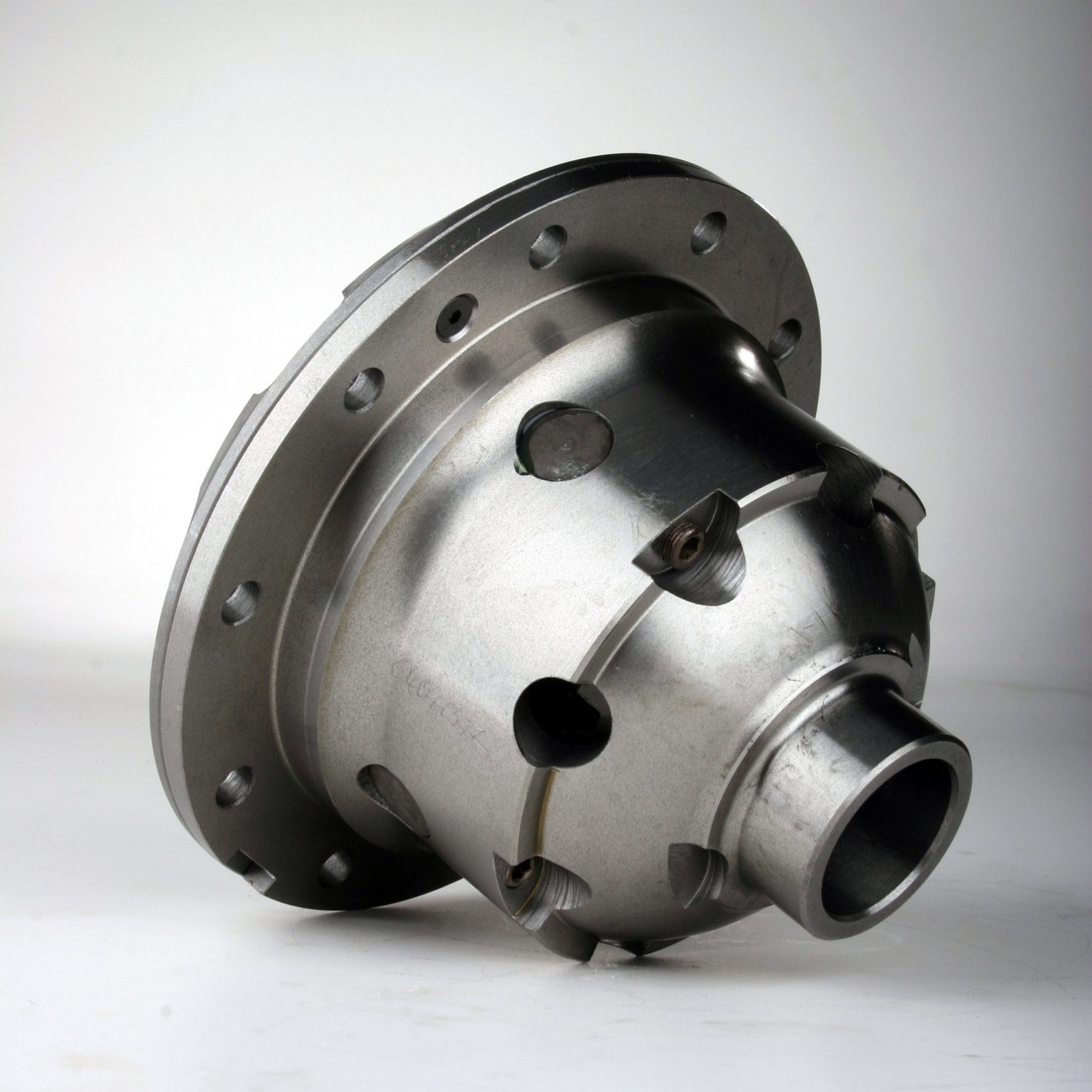
The ARB is perhaps the most versatile of the differential styles. It accomplishes this without compromising or biasing performance toward the street or the rocks. An ARB air locker is a driver-controlled locking differential that can be switched on or off when extra traction is required. When it’s off, it acts as an open differential. When it’s switched on, it essentially becomes a spool, providing the ultimate in 4×4 traction. To use the system, the driver activates the air locker via a dash-mounted switch. Pneumatic (air) pressure supplied by an onboard 12-volt air compressor engages the locking mechanism within the air locker, thus preventing the wheels from turning independently. The air locker is deactivated by flicking the switch, returning the differential to normal. Depending on your application, an ARB can be installed in the either the front, back or both differentials.
For Broncaroo, Steven opted to go the ARB route both front and rear because of the superior performance it offers on- and off-road.
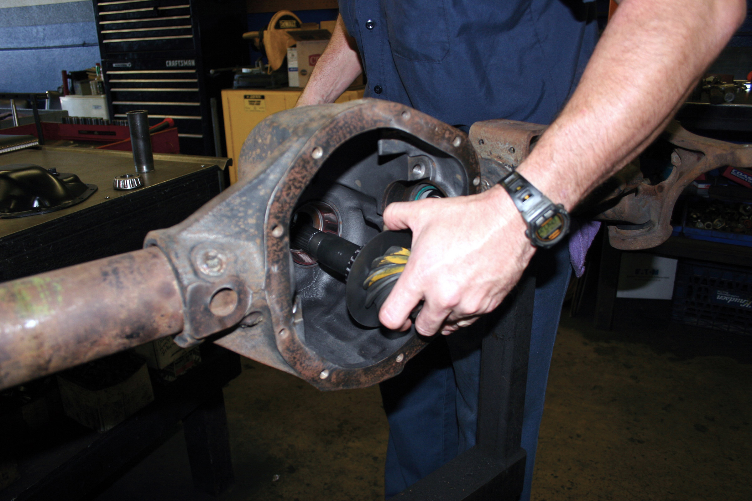
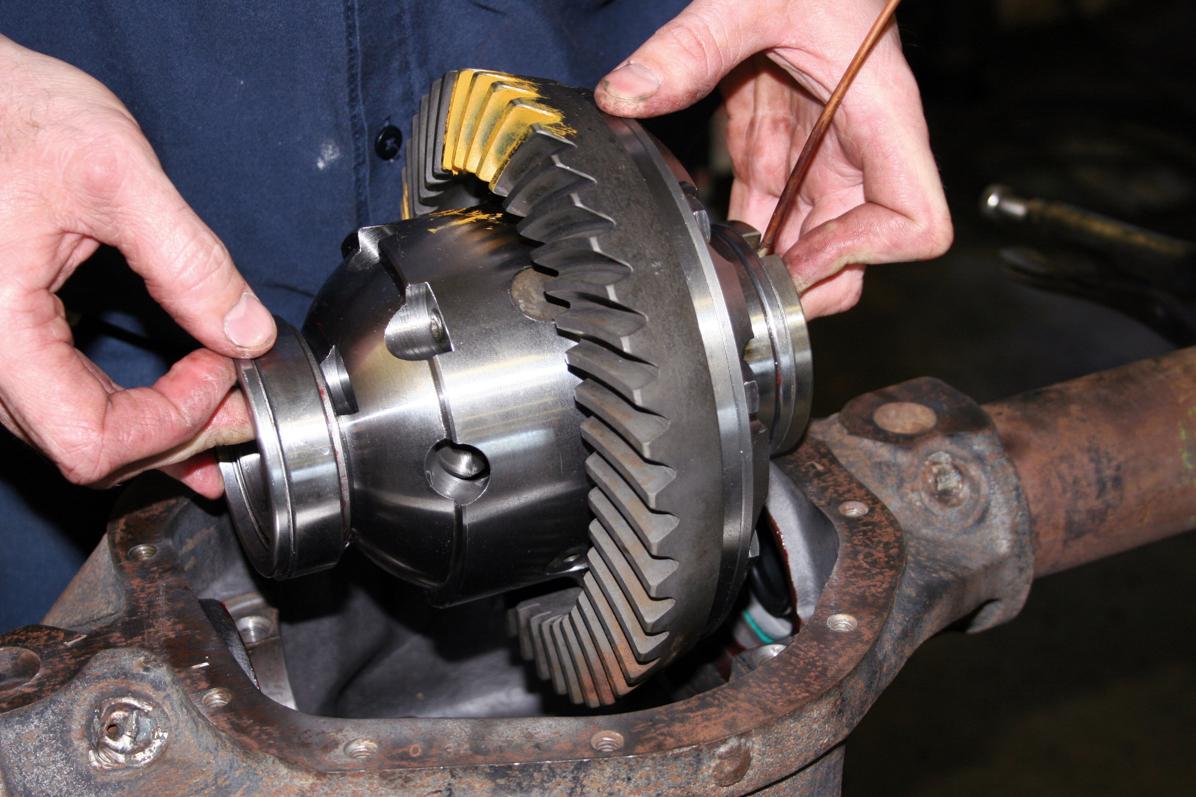
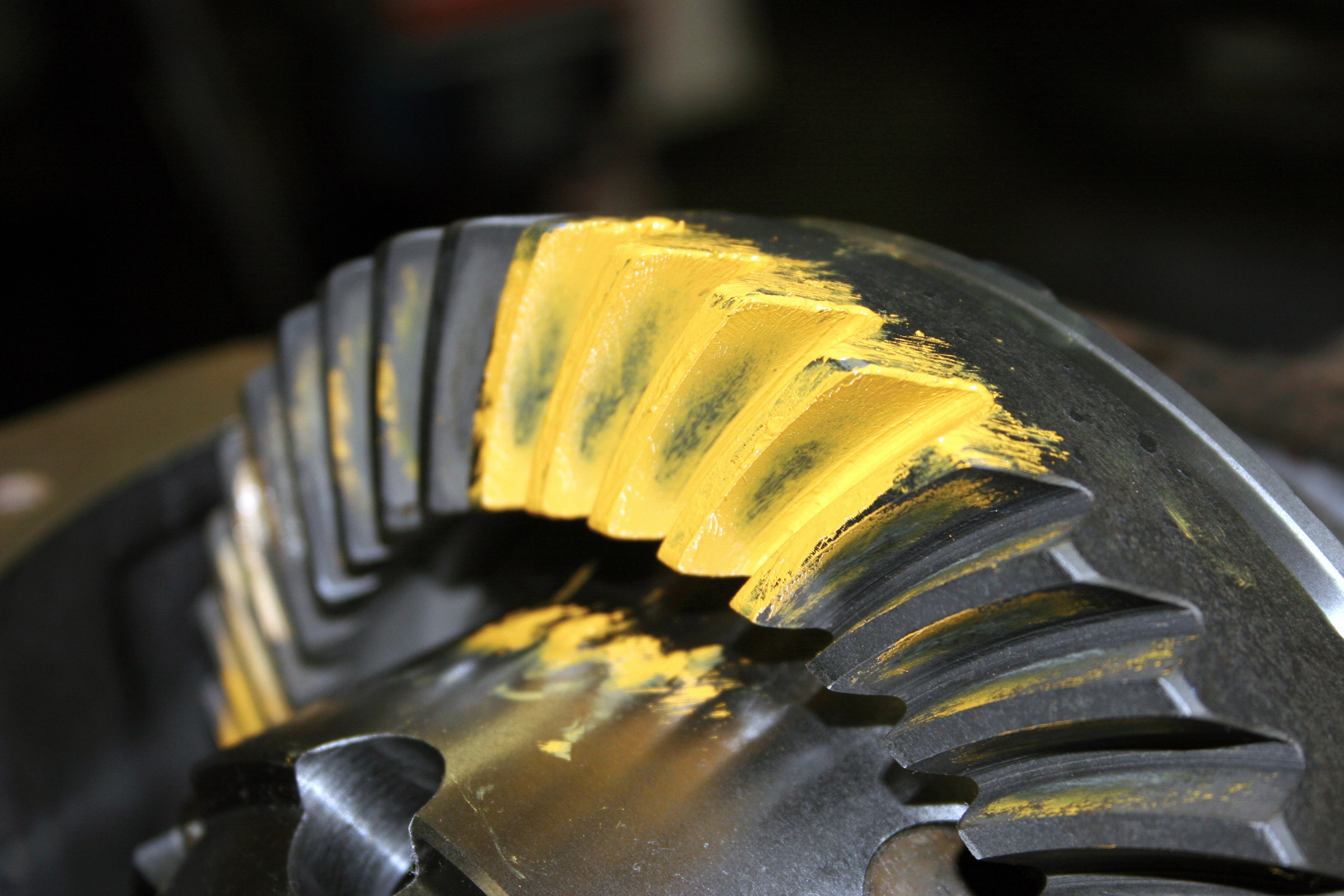
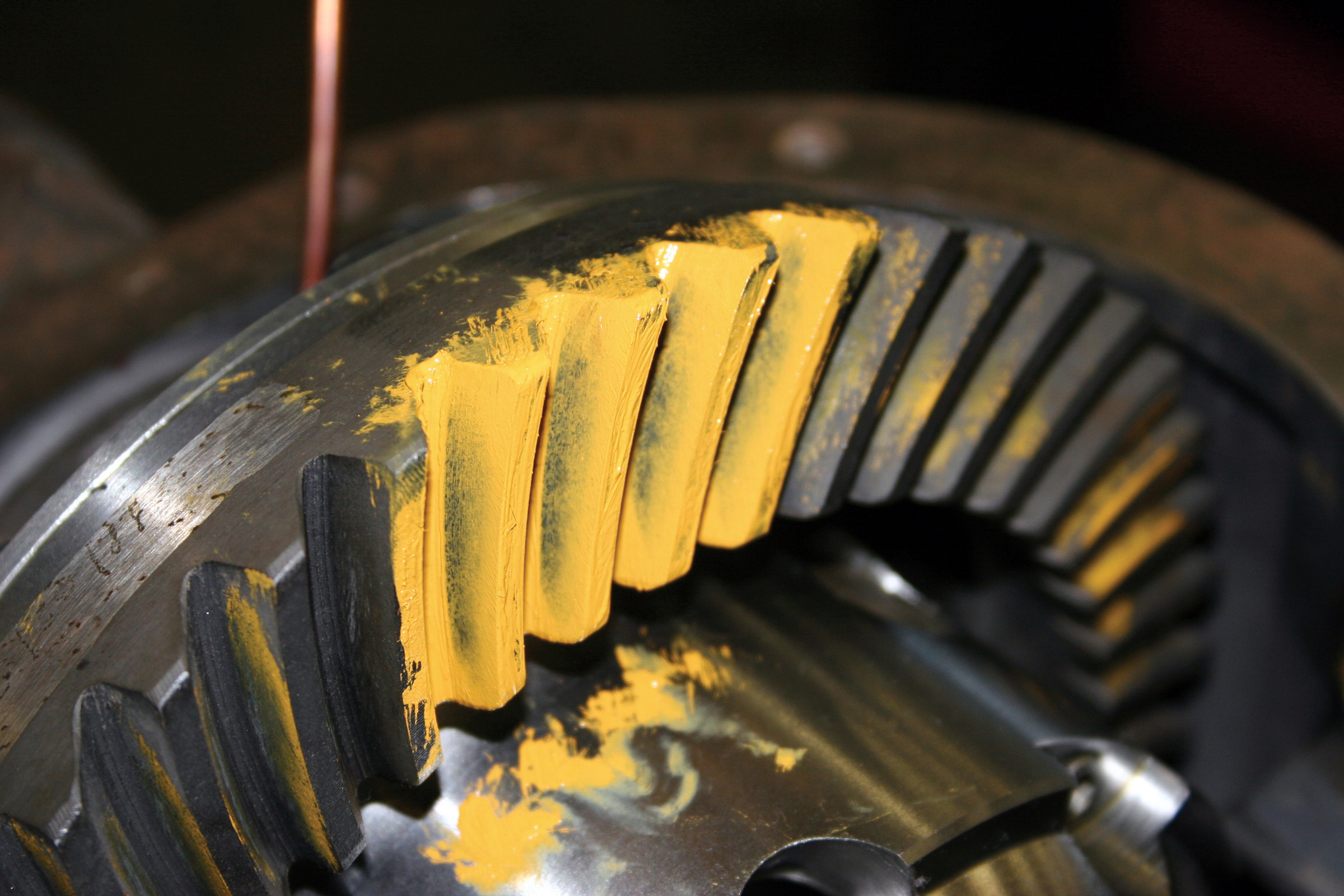
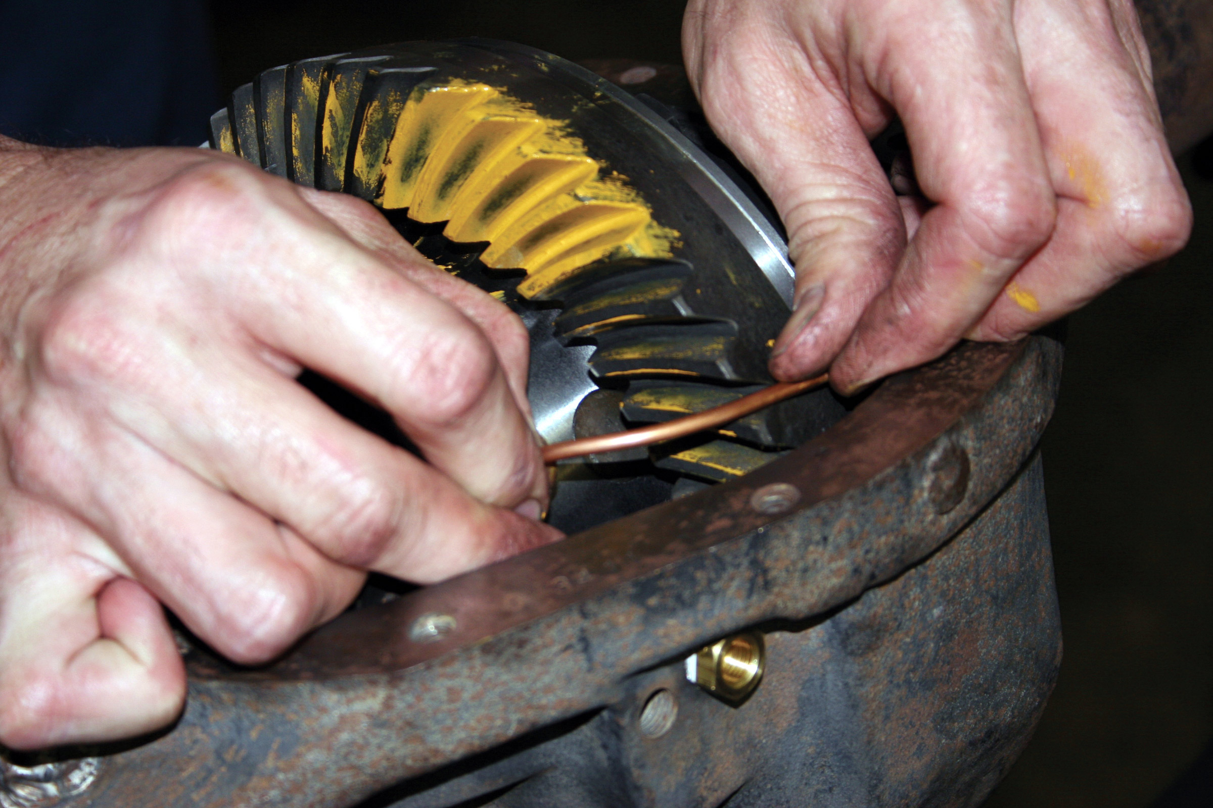
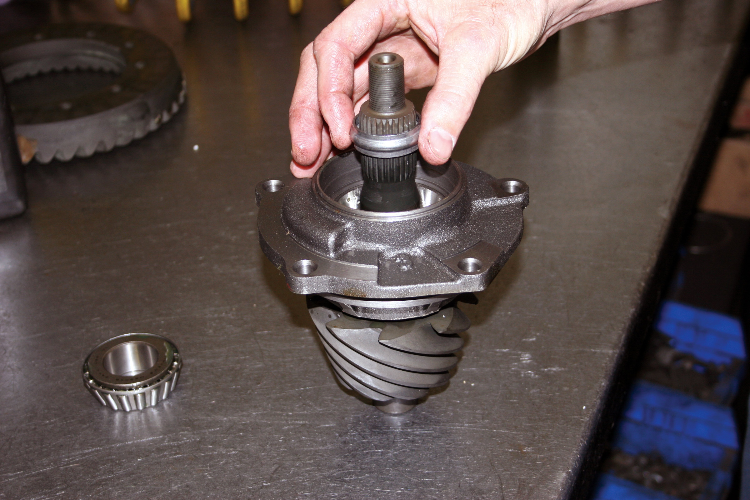
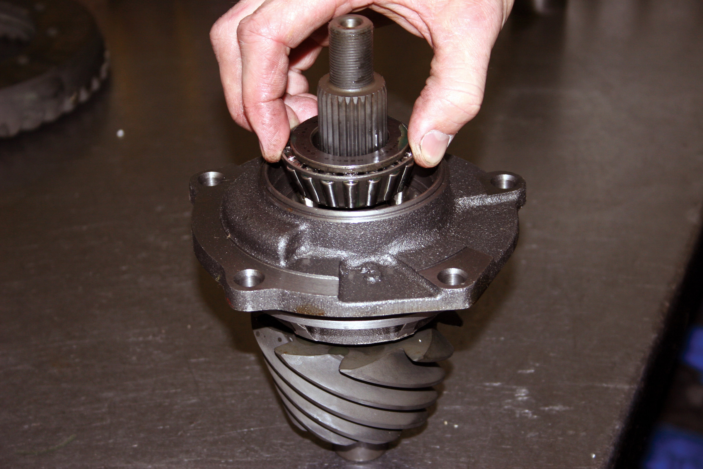
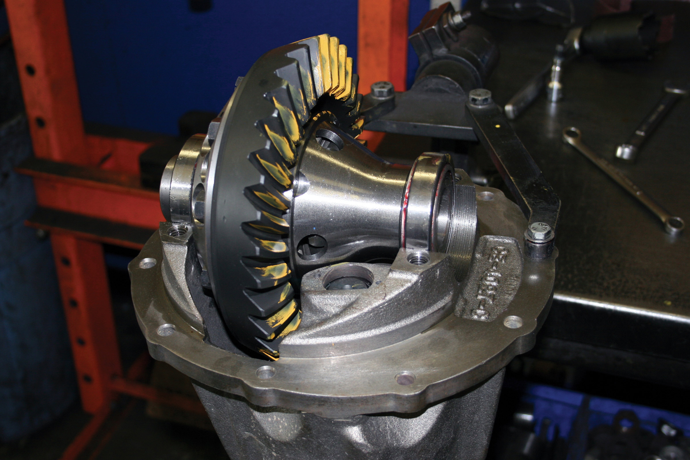
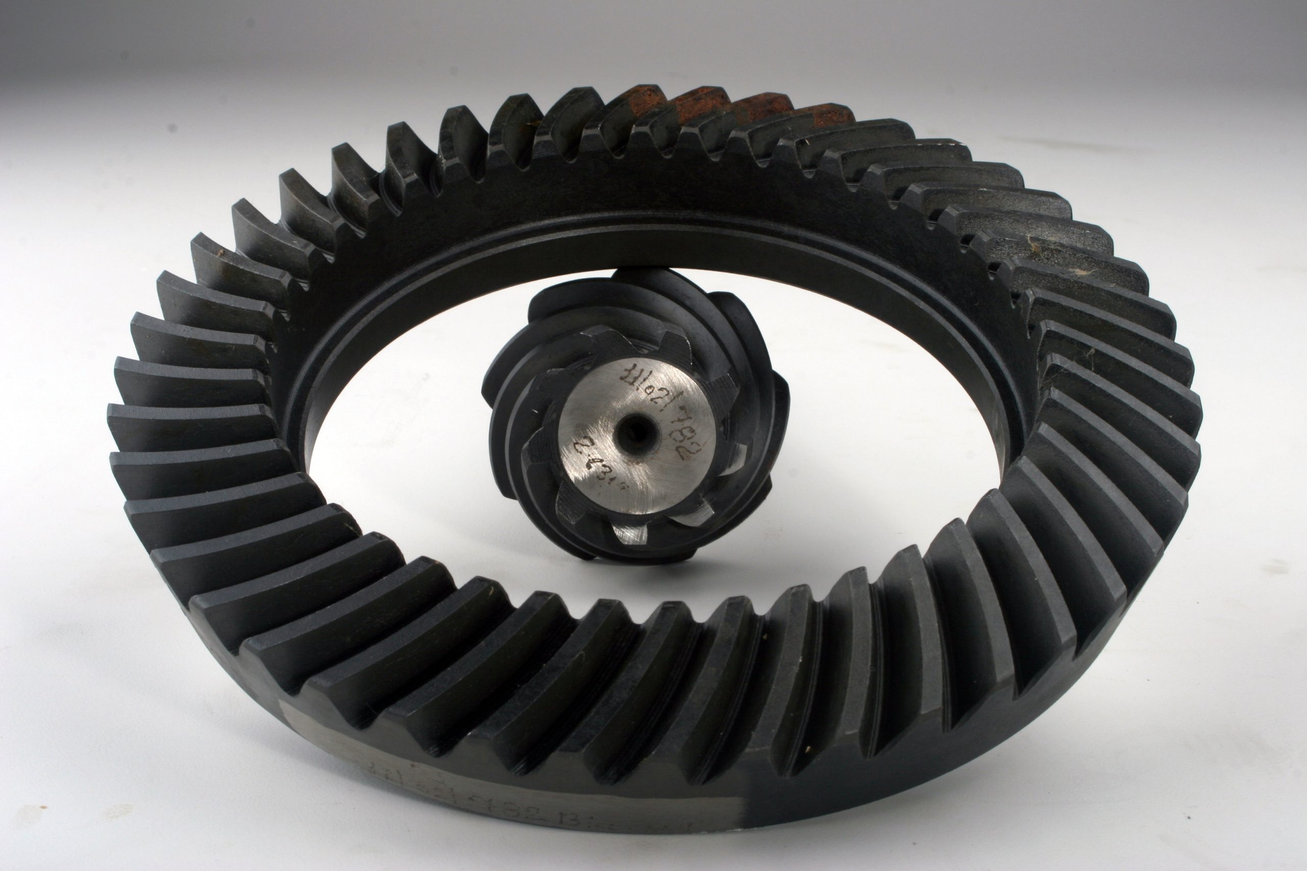
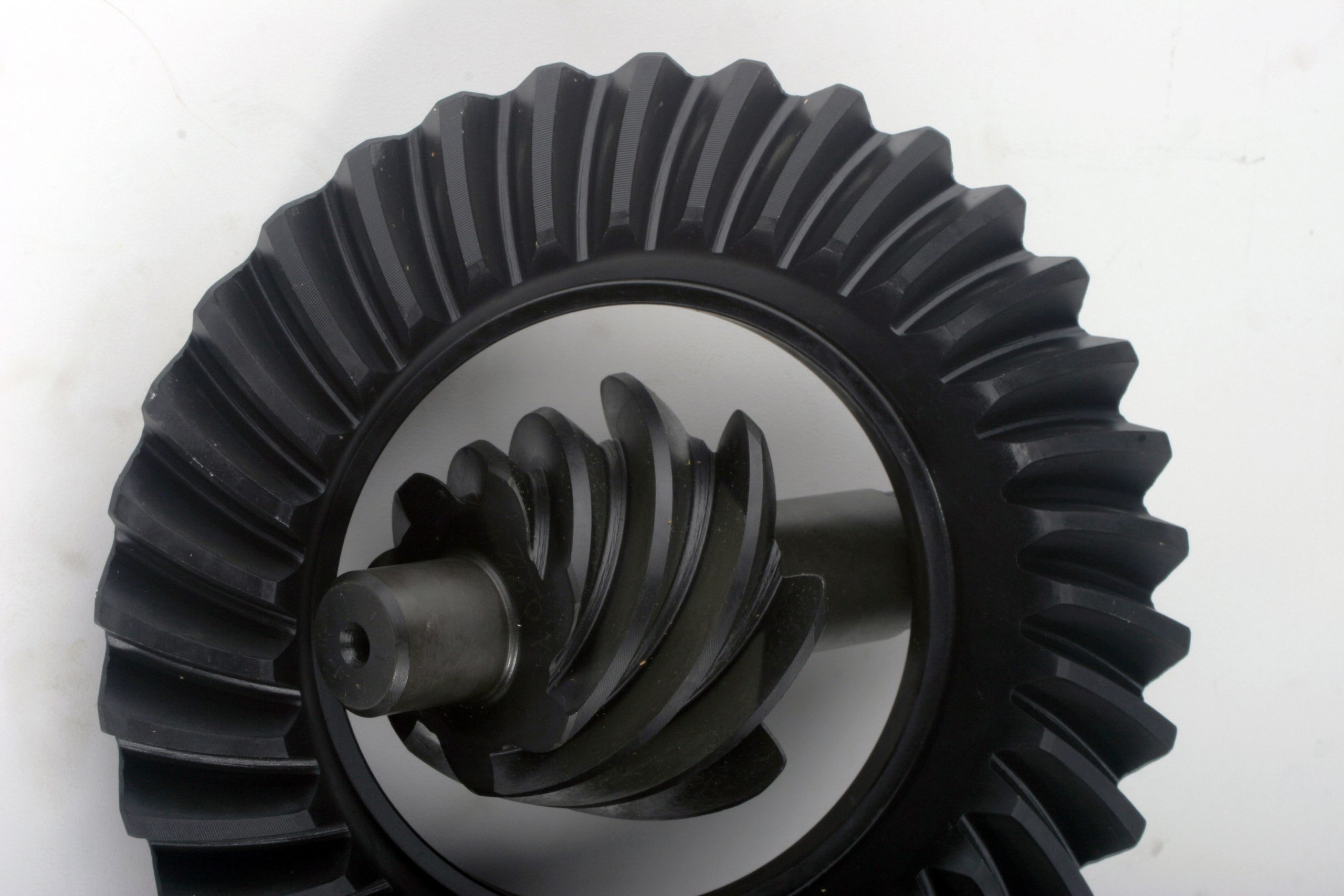
GEARING DOWN
To discuss gearing, we must first come to terms with gear jargon. Let’s see, higher is lower, so does that mean you go faster or slower? Gearing is expressed as a ratio–the ratio between the driven gear and the driving gear. In the case of differential gearing, we talk about the ratio formed by ring-and-pinion gears. The pinion gear is the driving gear, since it is motivated by engine torque routed to it through the driveline. The ring gear is turned by the pinion gear, so it is the driven gear. To learn the ratio, we divide the number of teeth on the pinion gear into the number of ring-gear teeth. Hence, if the ring gear has 30 teeth and the pinion gear has 11 (30 / 11 = 2.72), we have a 2.72:1 gear set, more commonly known as 2.73s due to rounding off. Let’s look at another set of ring and pinion gears with 39 and 8 teeth, respectively (39/8 = 4.875, or a ratio of 4.88:1). So which is a higher gear set, 2.72 or 4.88? Well, the 4.88s are the higher ratio numerically, but they are actually the lower gears when measured in terms of road speed verses engine rpm. The 4.88s also produce the greatest torque multiplication. Perhaps this analogy will help to make it clearer: The lowest/slowest gear in a transmission is first gear, but numerically it will have the highest, or largest, number. If our two ratio examples were in a transmission, the 4.88:1 would be first gear, while the 2.73:1 would be about third gear. So let’s agree to call the higher numerical ratios the lower gears.
It was not that long ago that gearing was pretty simple–but limiting. Most truck tires were measured in inches, and if you installed tires that were 10 percent larger in diameter, you would install ring-and-pinion gears that were 10 percent lower. Many manufacturers’ gears went only as low as 4.10:1. The world has changed, of course. Final-drive ratios have become very deep, but the larger part of the picture is the availability of overdrive transmissions combined with low first-gear ratios. The five-speed NV4500 with a 6.34:1 first-gear ratio and .73:1 overdrive is just one example that comes to mind. The 700R4 is also a hot transmission now, due to the aftermarket. It has a 3.06:1 first-gear ratio and a .07:1 overdrive and is a good choice for the auto crowd.
Aftermarket manufacturers such as Advance Adapters, JP and others make adapters to bolt these to nearly any engine or transfer case we can imagine. Likewise, many companies offer low-range transfer case gears in the 4:1 to 5:1 range. Some awesome crawl ratios are now easily achieved while retaining an acceptable highway gear. Crawl ratio is the final reduction after all gearing. It is easily calculated by simply multiplying all the ratios together. Take a 6.34 first-gear ratio, a 5.0 low range and 4.88 gears and you get 154:1! Crawl ratios starting at or lower than 45:1 are acceptable for all but the most serious of rock crawlers. Now that we have deep first gears, overdrives and 5:1 transfer cases, we no longer have to bias our final-drive choice in favor of either a low crawl ratio and lots of engine rpm on the road or decent highway rpm and steeper gearing off-road.
These factors don’t necessarily negate the need to change gears when going to larger rubber; we just want to give you some other things to think about rather than simply referring to some old gearing chart from the ’80s. Those old charts still work, despite new math. However, they do not allow for modern transmissions and a very creative and aggressive aftermarket full of alternate tranny and T-case gearing and the ability to swap almost anything anywhere.
Rather than bog you down with a bunch of mind-numbing formulas for converting metric-size tires to inches or calculating engine rpm verses mph for a given tire and gear, among many other needed calculations, we’re going to point you to the internet. We sat here compiling all the math and our brains froze over. However, many of the gear and tire companies have really cool calculators that allow one to quickly compare all the gearing considerations and options. We have listed just a few for you.
