


THE AUTO BUILDER
Featured
- All Post
- _000 HIGH PRIORITY
- Trucks
- Swaps
- Performance Boats
- Builders
- 00 Sidebars
- Manufacturers
- _000 Home Sliders
- 05 Publications
- Builds
- Cars
- 01 Post Status
- Back
- Street Rods
- Hot Rods
- Late Model
- Drag Race
- Handling
- Compact Cars
- Fuel System
- Electrical
- Exhaust
- Transmission / Drivetrain
- Suspension
- Steering
- Brakes
- Wheels and Tires
- Interior
- Exterior
- Accessories
- Chassis
- Engine
- Power Adders
- Transmission / Drivetrain
- Suspension
- Steering
- Brakes
- Wheels and Tires
- Interior
- Exterior
- Accessories
- Chassis
- Engine
- Fuel System
- Power Adders
- Electrical
- Exhaust
- Brakes
- Wheels and Tires
- Interior
- Exterior
- Accessories
- Chassis
- Engine
- Electrical
- Exhaust
- Fuel System
- Transmission / Drivetrain
- Suspension
- Power Adders
- Steering
- Exterior
- Accessories
- Power Adders
- Chassis
- Engine
- Electrical
- Exhaust
- Fuel System
- Transmission / Drivetrain
- Suspension
- Steering
- Brakes
- Wheels and Tires
- Interior
- Power Adders
- Chassis
- Engine
- Electrical
- Exhaust
- Fuel System
- Transmission / Drivetrain
- Suspension
- Steering
- Brakes
- Wheels and Tires
- Interior
- Exterior
- Accessories
- Engine
- Fuel System
- Electrical
- Power Adders
- Exhaust
- Transmission / Drivetrain
- Suspension
- Steering
- Brakes
- Wheels and Tires
- Interior
- Exterior
- Accessories
- Chassis
- Back
- Fuel System
- Electrical
- Exhaust
- Transmission / Drivetrain
- Suspension
- Steering
- Brakes
- Wheels and Tires
- Interior
- Exterior
- Accessories
- Chassis
- Engine
- Power Adders
- Back
- Transmission / Drivetrain
- Suspension
- Steering
- Brakes
- Wheels and Tires
- Interior
- Exterior
- Accessories
- Chassis
- Engine
- Fuel System
- Power Adders
- Electrical
- Exhaust
- Back
- Brakes
- Wheels and Tires
- Interior
- Exterior
- Accessories
- Chassis
- Engine
- Electrical
- Exhaust
- Fuel System
- Transmission / Drivetrain
- Suspension
- Power Adders
- Steering
- Back
- Power Adders
- Chassis
- Engine
- Electrical
- Exhaust
- Fuel System
- Transmission / Drivetrain
- Suspension
- Steering
- Brakes
- Wheels and Tires
- Interior
- Exterior
- Accessories
- Back
- Engine
- Fuel System
- Electrical
- Power Adders
- Exhaust
- Transmission / Drivetrain
- Suspension
- Steering
- Brakes
- Wheels and Tires
- Interior
- Exterior
- Accessories
- Chassis
- Back
- Fuel System
- Electrical
- Exhaust
- Transmission / Drivetrain
- Power Adders
- Suspension
- Steering
- Brakes
- Wheels and Tires
- Interior
- Exterior
- Accessories
- Chassis
- Engine
- Back
- Transmission / Drivetrain
- Suspension
- Steering
- Brakes
- Wheels and Tires
- Power Adders
- Interior
- Exterior
- Accessories
- Chassis
- Engine
- Fuel System
- Electrical
- Exhaust
- Back
- Chrysler
- Subaru
- Plymouth
- Mercury
- Chevrolet
- Volvo
- Cadillac
- Volkswagen
- Pontiac
- GMC
- AMC
- BMW
- Buick
- Jeep
- Oldsmobile
- Lincoln
- Mitsubishi
- Ford
- Dodge
- Acura
- Honda
- Nissan
- Toyota
- Back
- 05 Post Imported
- 20 Post Missing Images (All)
- 25 Post Missing Images (Partial)
- 15 Post In Progress
- 30 Post Internal Review
- 40 Post On Hold
- 50 Post Approved
- 10 Post Images Imported
- 27 Post Missing Content
- 17 Post Missing TXT Files
- 18 Post Missing PDF Files
- Back
- 05 Pub HCI Hot Compact Imports
- 15 Pub 4x4 4x4 Builder
- 20 Pub SR Super Rod
- 25 Pub FB Ford Builder
- 30 Pub AR American Rodder
- 35 Pub RD Rodders Digest
- 40 Pub OTR On the Road
- 55 Pub BSCENE Buckaroo Scene
- 10 Pub CR Chevy Rumble
- 50 Pub TB Truck Builder
- 60 Pub FPB Family Power Boat
- 45 Pub SRB Street Rod Builder
- Back
- 10 High Priority - CR Chevy Rumble
- 15 High Priority - 4x4 4x4 Builder
- 20 High Priority - SR Super Rod
- 25 High Priority - FB Ford Builder
- 30 High Priority - AR American Rodder
- 35 High Priority - RD Rodders Digest
- 40 High Priority - OTR On the Road
- 45 High Priority - SRB Street Rod Builder
- 50 High Priority - TB Truck Builder
- 55 High Priority - BSCENE Buckaroo Scene
- 60 High Priority - FPB Family Power Boat
- 05 High Priority - HCI Hot Compact Imports
- Back
- Exterior
- Accessories
- Power Adders
- Chassis
- Engine
- Electrical
- Exhaust
- Fuel System
- Transmission / Drivetrain
- Suspension
- Steering
- Brakes
- Wheels and Tires
- Interior
- Back
- Steering
- Interior
- Accessories
- Power Adders
- Exterior and Hull
- Engine
- Fuel System
- Electrical
- Outdrives
- Back
- J.F. Launier
- Bobby Alloway
- Chip Foose
- Steve Sellers
- Boyd Coddington
- Rad Rides by Troy
- Ring Brothers
- Cal Auto Creations
- George Barris
- Jesse James
- Jack Fuller
- Bob Cullipher
- Jerry Nichols
- Carl Casper
- Back
- Chassis
- Engine Swaps
- Interior Swaps
- Driveline
- Back
- Street Trucks
- OffRoad Trucks
- Fuel System
- Electrical
- Exhaust
- Transmission / Drivetrain
- Power Adders
- Suspension
- Steering
- Brakes
- Wheels and Tires
- Interior
- Exterior
- Accessories
- Chassis
- Engine
- Transmission / Drivetrain
- Suspension
- Steering
- Brakes
- Wheels and Tires
- Power Adders
- Interior
- Exterior
- Accessories
- Chassis
- Engine
- Fuel System
- Electrical
- Exhaust
- Back
- 01 Sidebar Left
- 01 Sidebar Right
HOW TO BUILD A DEUCE HIGHBOY
There Are Many Angles for Building a Deuce Highboy, but This One Uses All Over-the-Counter Parts
Author

John Dianna
Photography by Scott Killeen
Approaches to Building a Street Rod
Make no mistake, there are numerous approaches that can be taken to complete just about any street rod project for just about any price. While the combination offered here is, by design, an entry-level one, if taken to the extremes, it could even accumulate a cost of up to six figures. It could also be less than half that amount.
A Cost-Effective Alternative
The point of this presentation is to provide a less expensive alternative while still enabling an enthusiast to complete the vehicle of his choice, which—in this case—is the venerable ’32 Ford. There are any number of used street rods on the used-car market. Some are actually for sale and priced accordingly while others are simply advertised to see what the market will bring. And while we are advocating the construction of many different types of street rods, when it comes to an affordable alternative, there is no denying the attraction of the fenderless roadster.
Availability of Parts and Cost Estimates
With fenders or not, an early-’30s roadster is easy to build, and there are a great number of parts available for them. Some manufacturers are offering a roller for under $12,000, considering the use of a crate motor (and if you are handy, you could conceivably bring the overall cost of the project to around $25,000). Using selected components from various manufacturers, we would estimate a completed project cost to be $25,000 to $38,000. A work in progress could better all these numbers as you can then cherry-pick the parts as you go along. Many manufacturers offer exceptional deals at various shows throughout the Midwest, southern states, and the East Coast. They sell show specials that beat even the prices quoted in magazines, such as the one you are holding. Over-stocked items, discontinued part numbers, and new introductions are frequently sold at far less than the going rate. If you are not picky, you could accessorize your project, attend events, and still save on the project, and we haven’t even mentioned using vintage or used parts from swap meets and the Internet.
The Debate on Entry-Level Costs
As you can imagine, there is a great deal of controversy, even in our own office, about what an entry-level car would cost to build. Many leading car constructors claim that it takes 1,000 hours of labor, over and above the cost of the parts. You do the math. At a shop rate of $50 per hour, labor will cost $50,000 on top of the $20,000 or so you spent for the frame, body, chassis, drivetrain, and associated parts to go, stop, and steer the thing. For openers, that’s $70,000! If you are married with a family, that could be darn similar to selling refrigerators to Eskimos. We have even heard the idea of assembly line-built roadsters being sold out the door for under $30,000. Whether or not it would be worth all the effort or even be possible, I don’t know. If you look around, many more reputable shops would rather sell parts. However, those who are committed to building cars over the long haul have booked their work years in advance. It is not uncommon to hear a shop owner tell a customer he can’t touch a car until a particular time because he has nearly three dozen complete ground-up builds lined up before he can start.
The Reality of Turnkey Builds
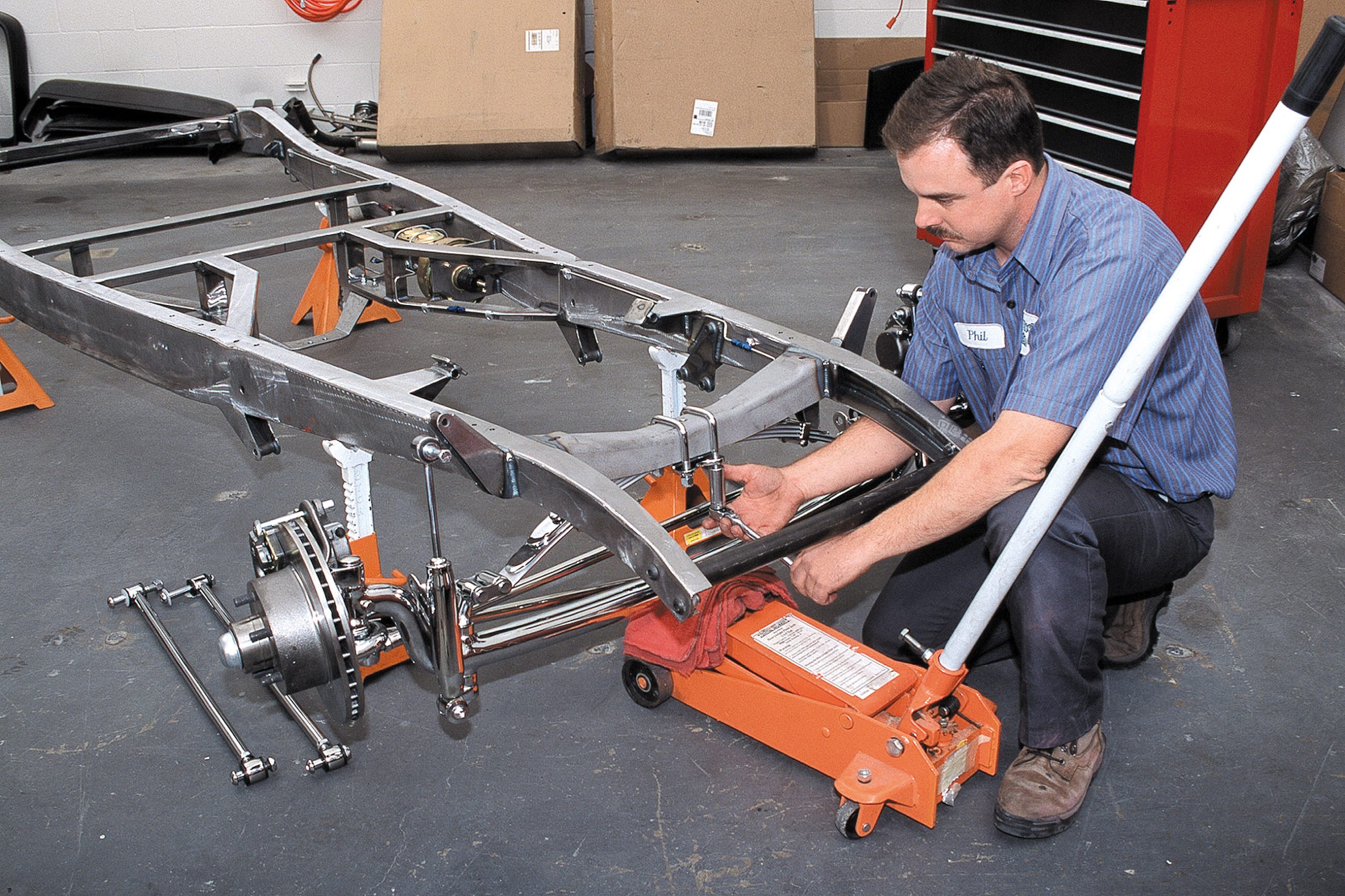
This kind of demand for turnkey cars does little to reduce the hourly shop rate or drive down the price of tin. On the contrary, everything is getting more costly. The most logical choice for an inexperienced car builder is to buy your buildable car through a reputable shop so that during the life of the project, they will help push the project toward completion by taking on the jobs that are beyond the capability and available equipment of the novice car builder. This also guarantees that the vehicle being built is a project buildup and not something that was thoughtlessly purchased along the way.
Roadsters and Alternative Options
Roadsters are not for everybody, nor can they be driven throughout tough weather climates for as long during the year as cars in more tropical climates. Although a roadster is less expensive to build, particularly a highboy, it shouldn’t be the go/no-go deciding factor as there are actually better package deals from a variety of sources for different cars. One comes to mind that we are thinking of building ourselves, and that is the ’32 highboy sedan. It already has a top, but there is the cost of the windows, window registers, and more body to finish and paint, and the interior will possibly cost slightly more. Summed up, it’s doubtful that we’re talking more than $1,500-$2,000 to finish the car the right way, so it really boils down to the acquisition price and how much of the work you can do yourself. There could be other sleeper cars as well.
The Build Process and Final Investment
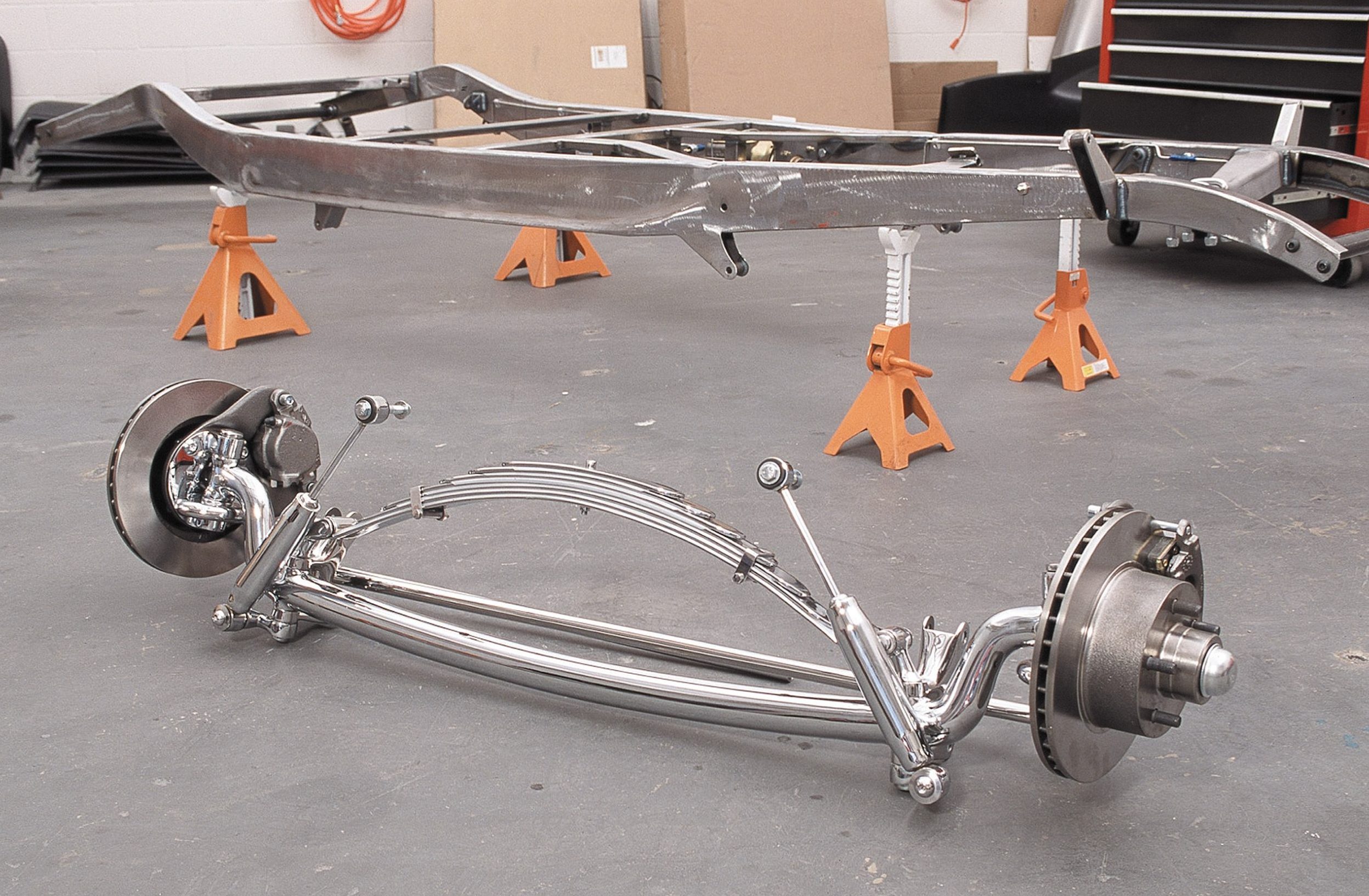
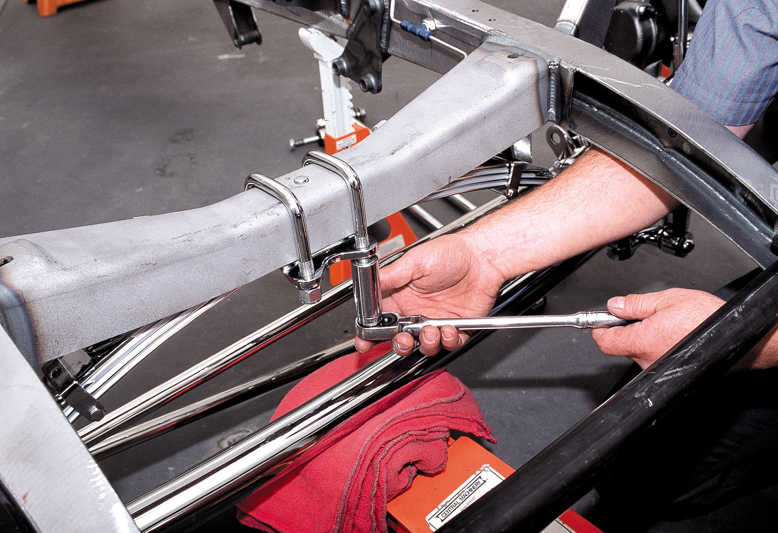
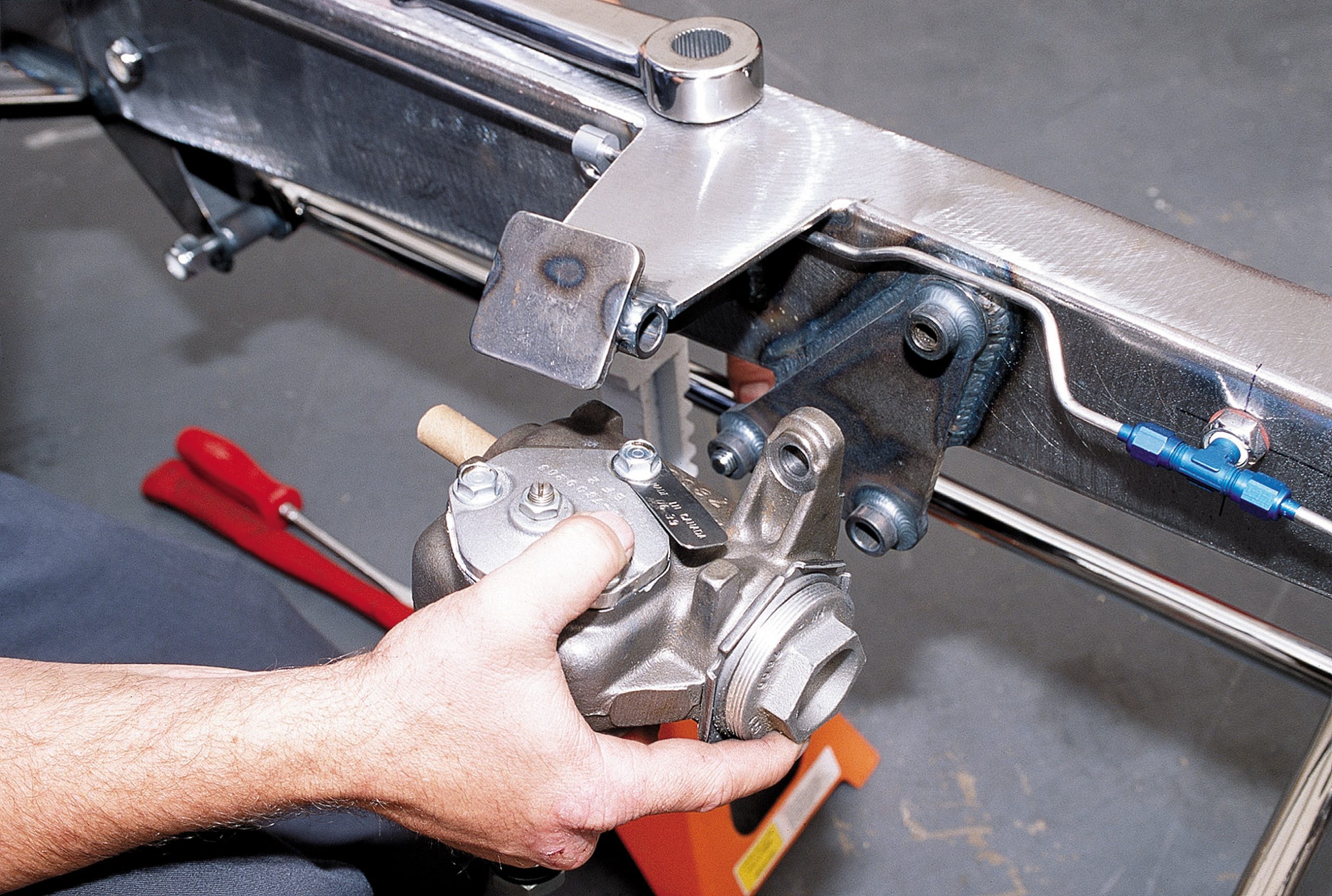
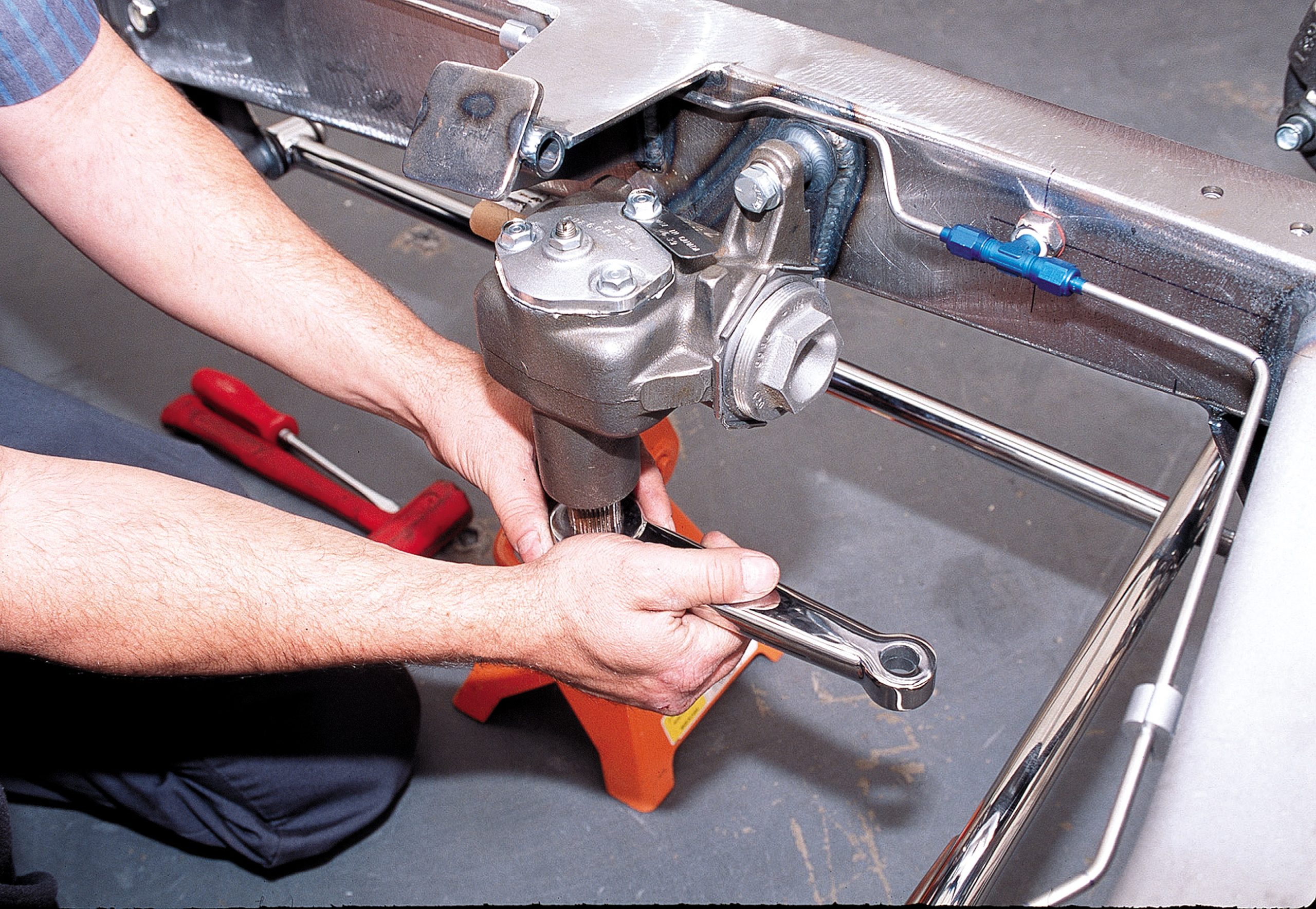
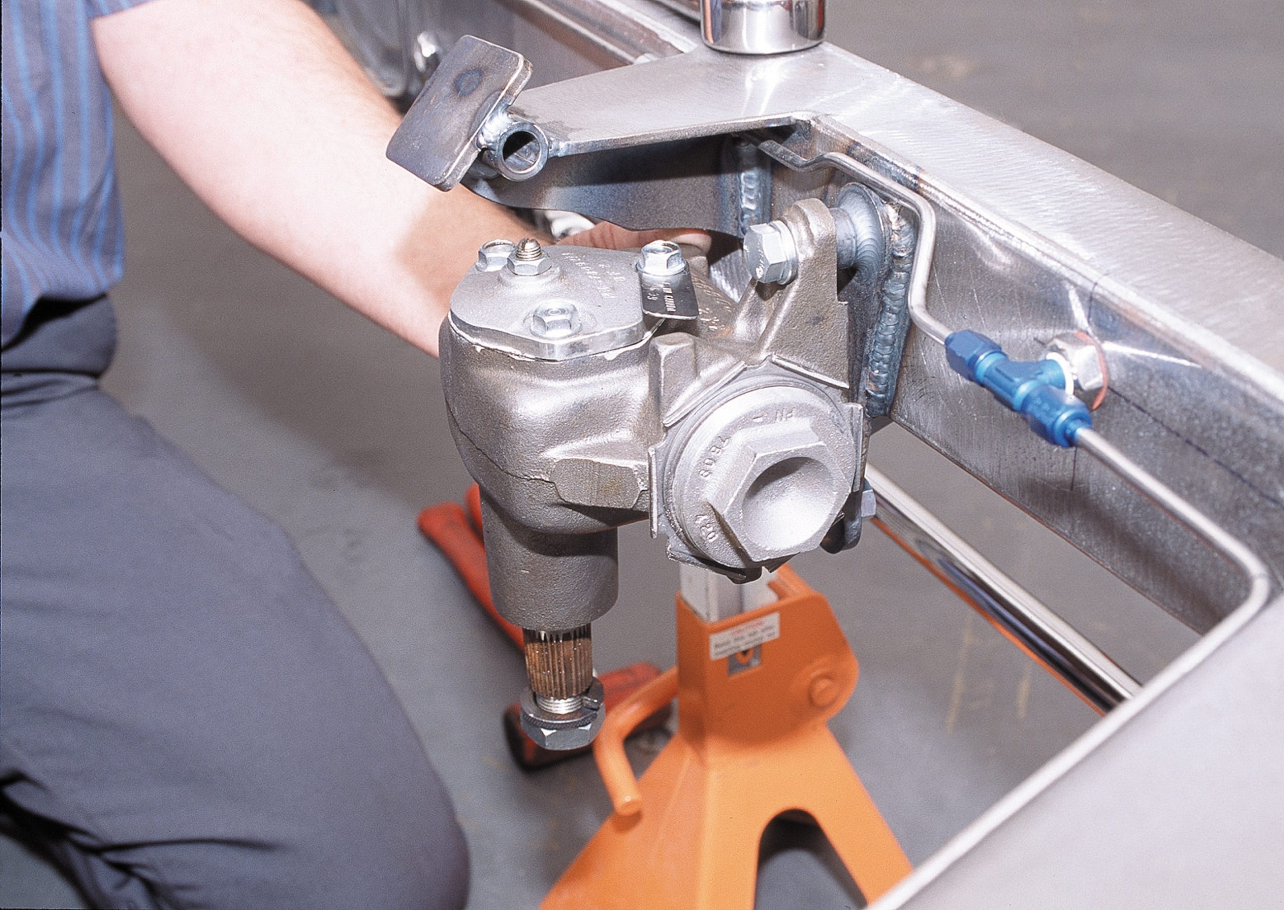
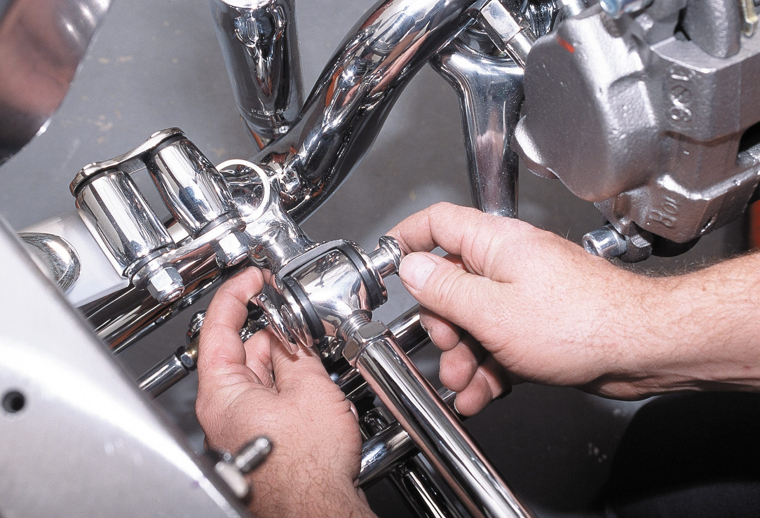
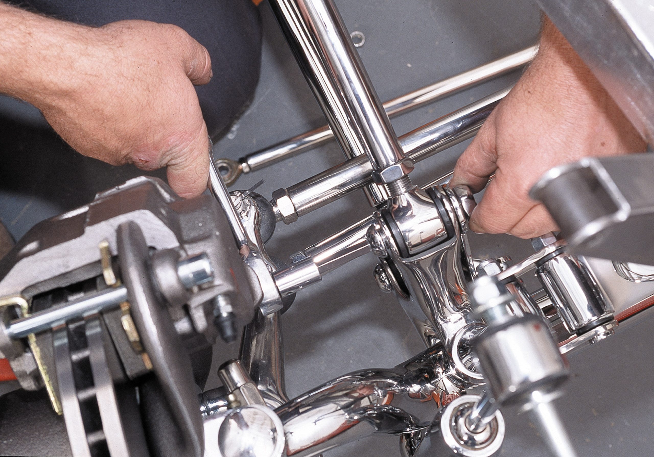
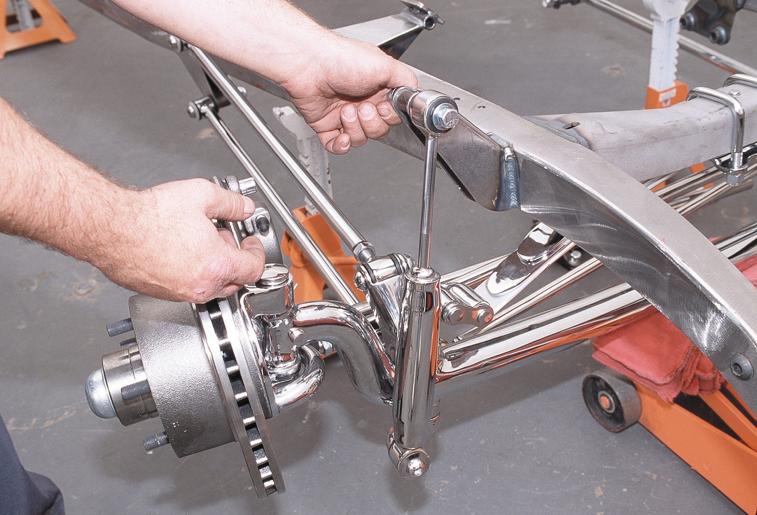
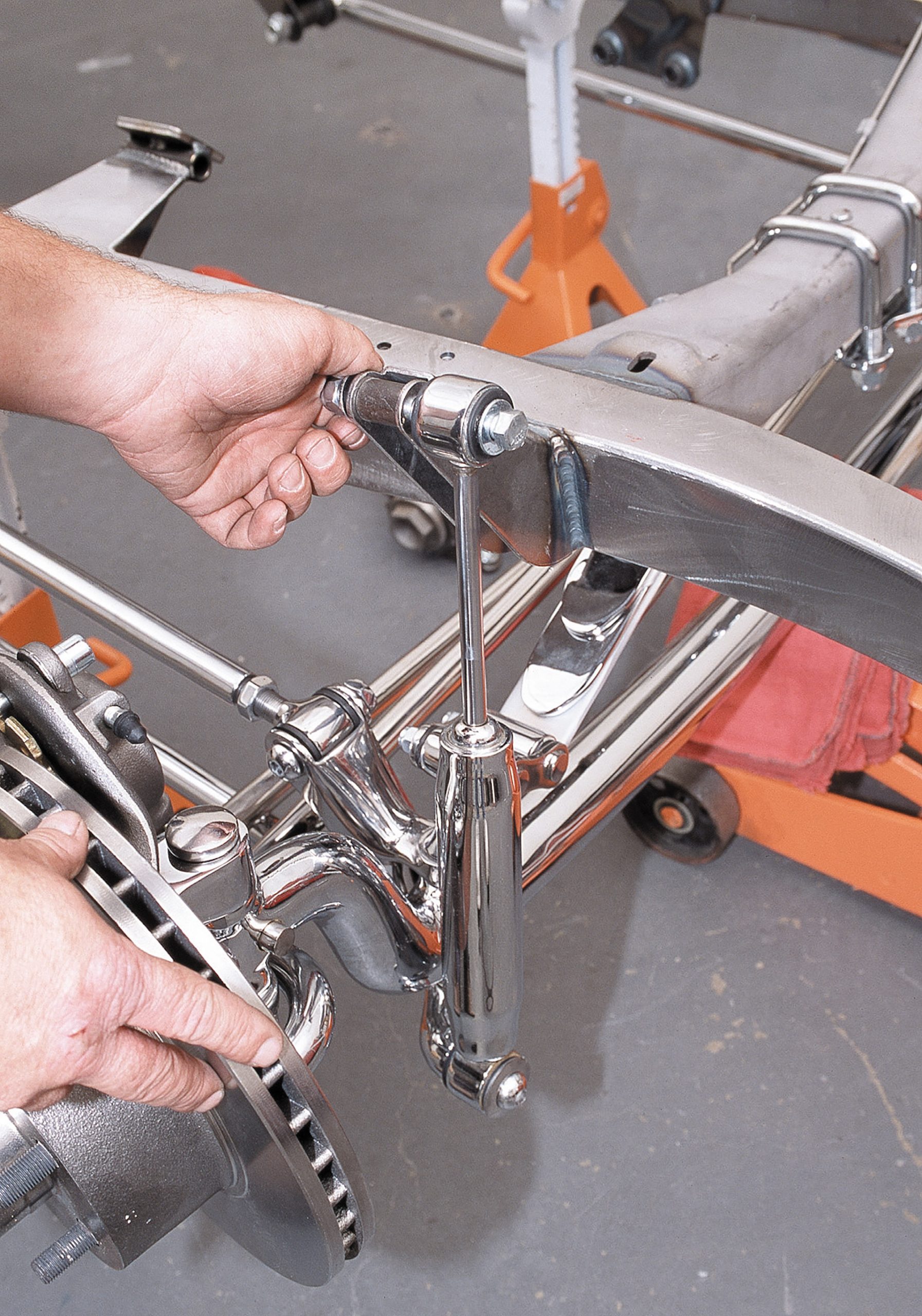
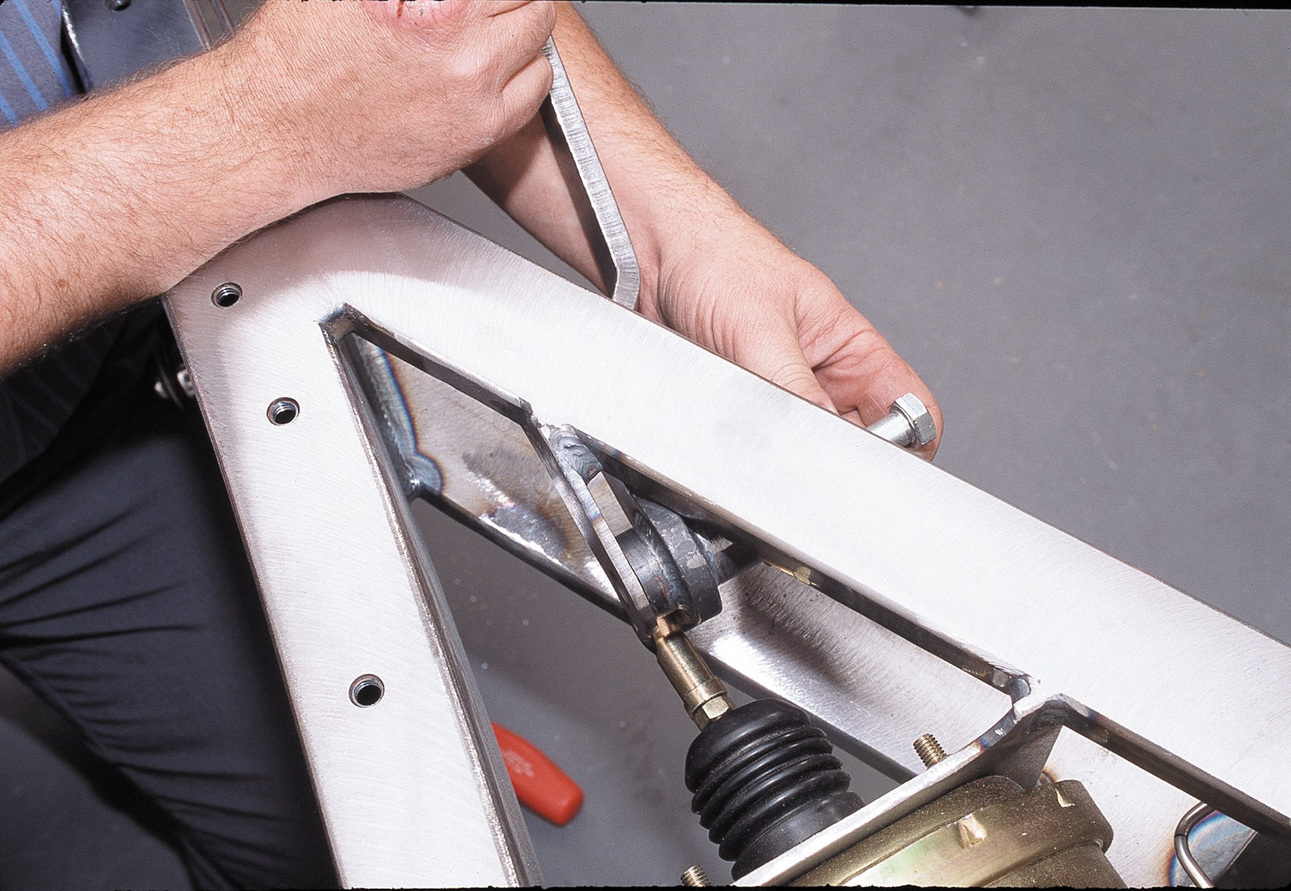
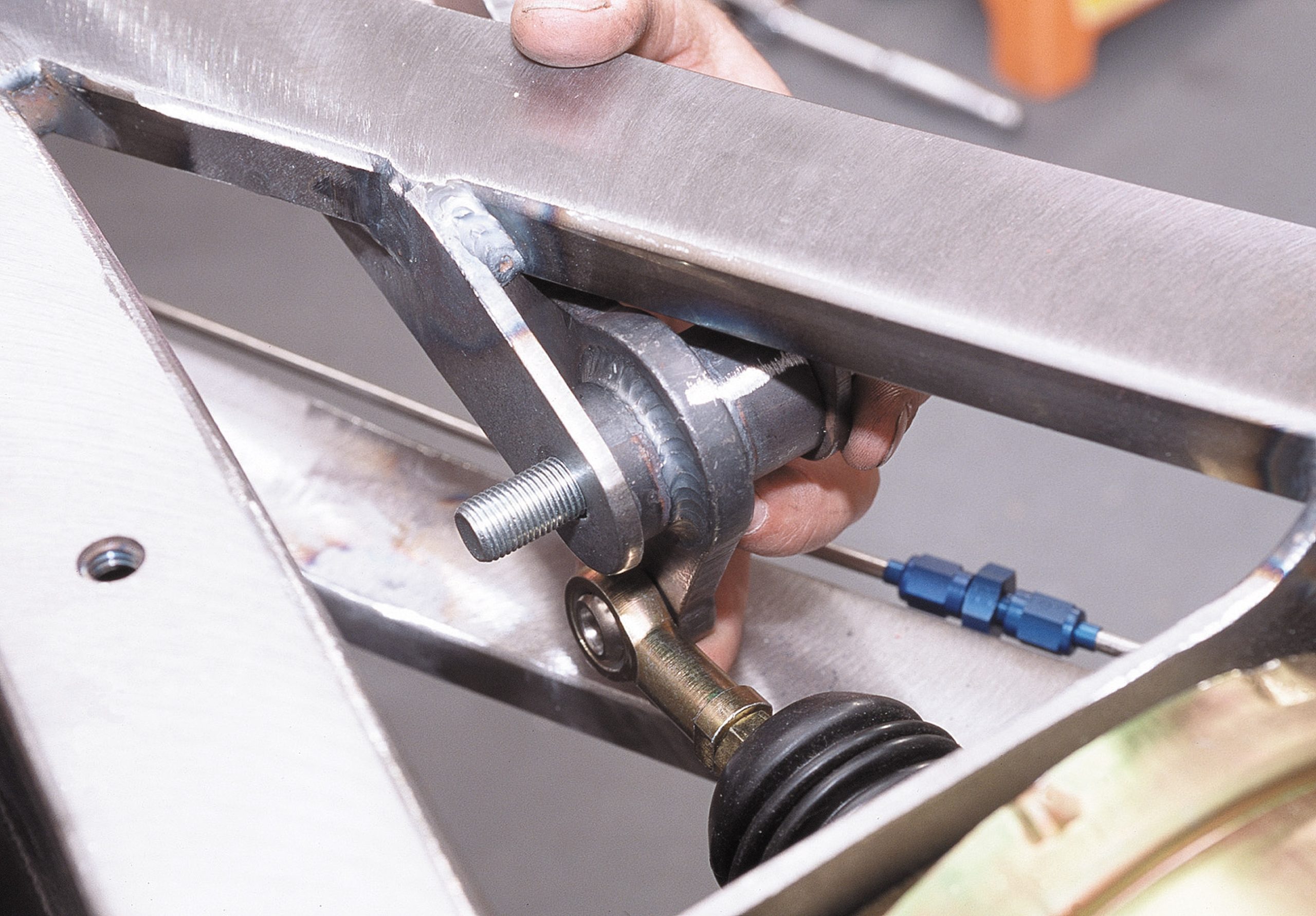
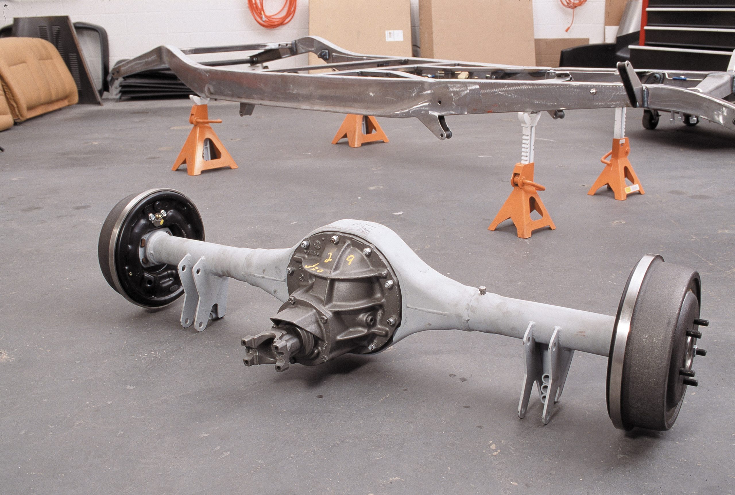
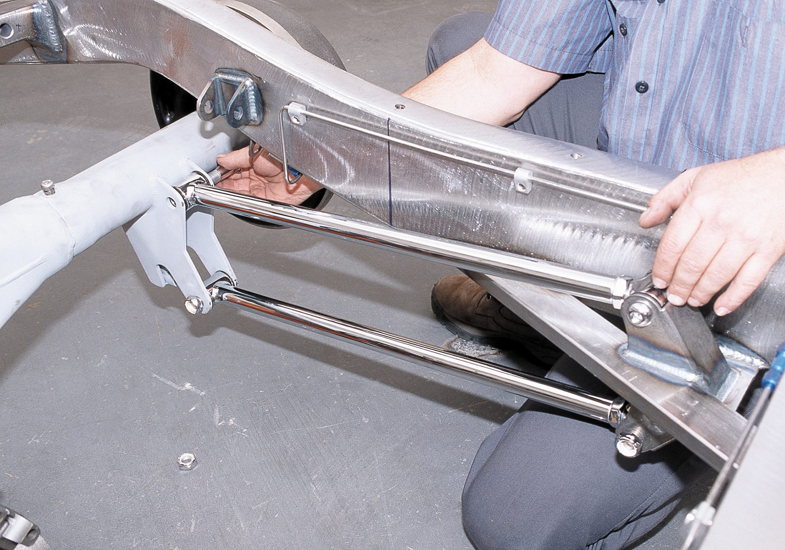
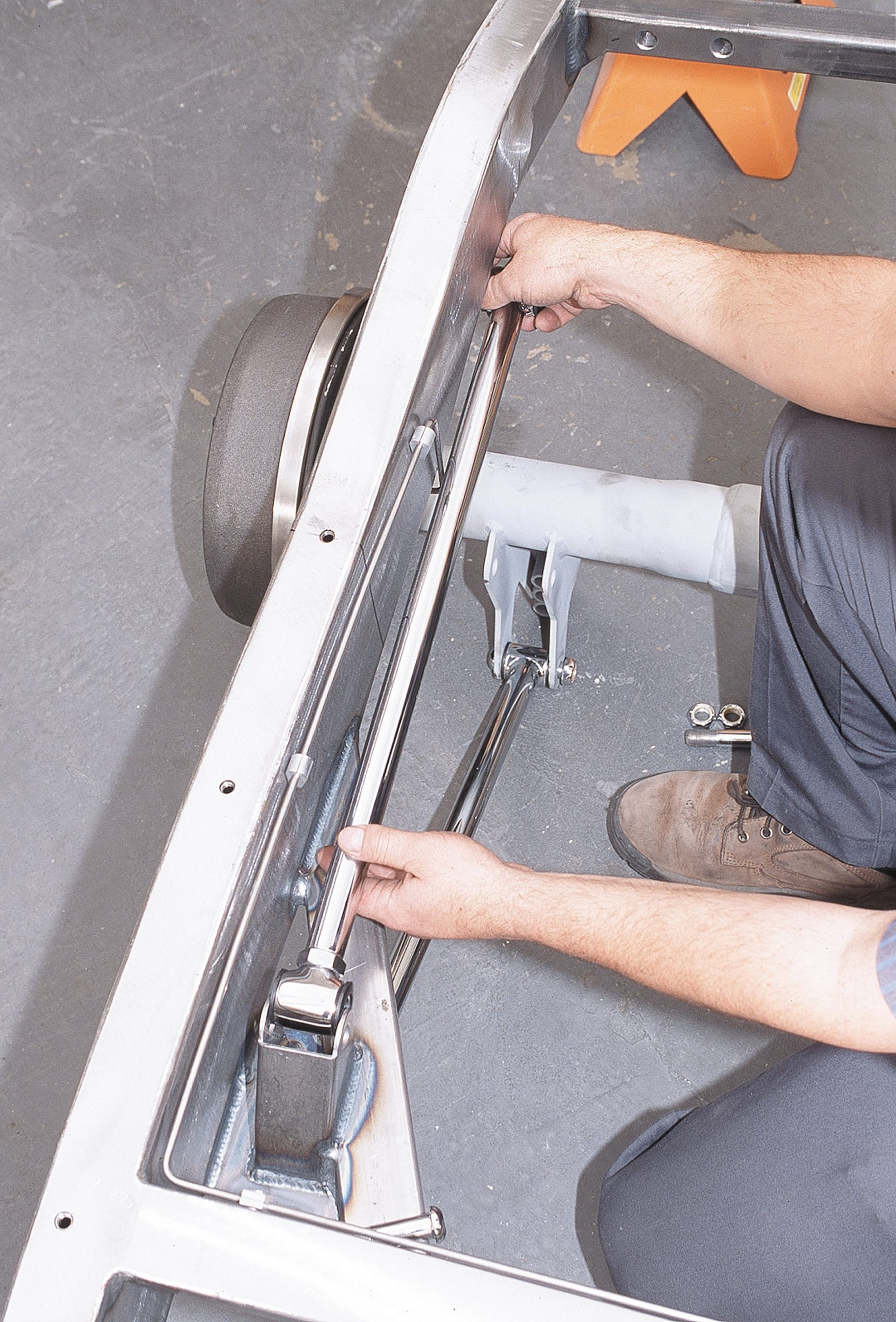
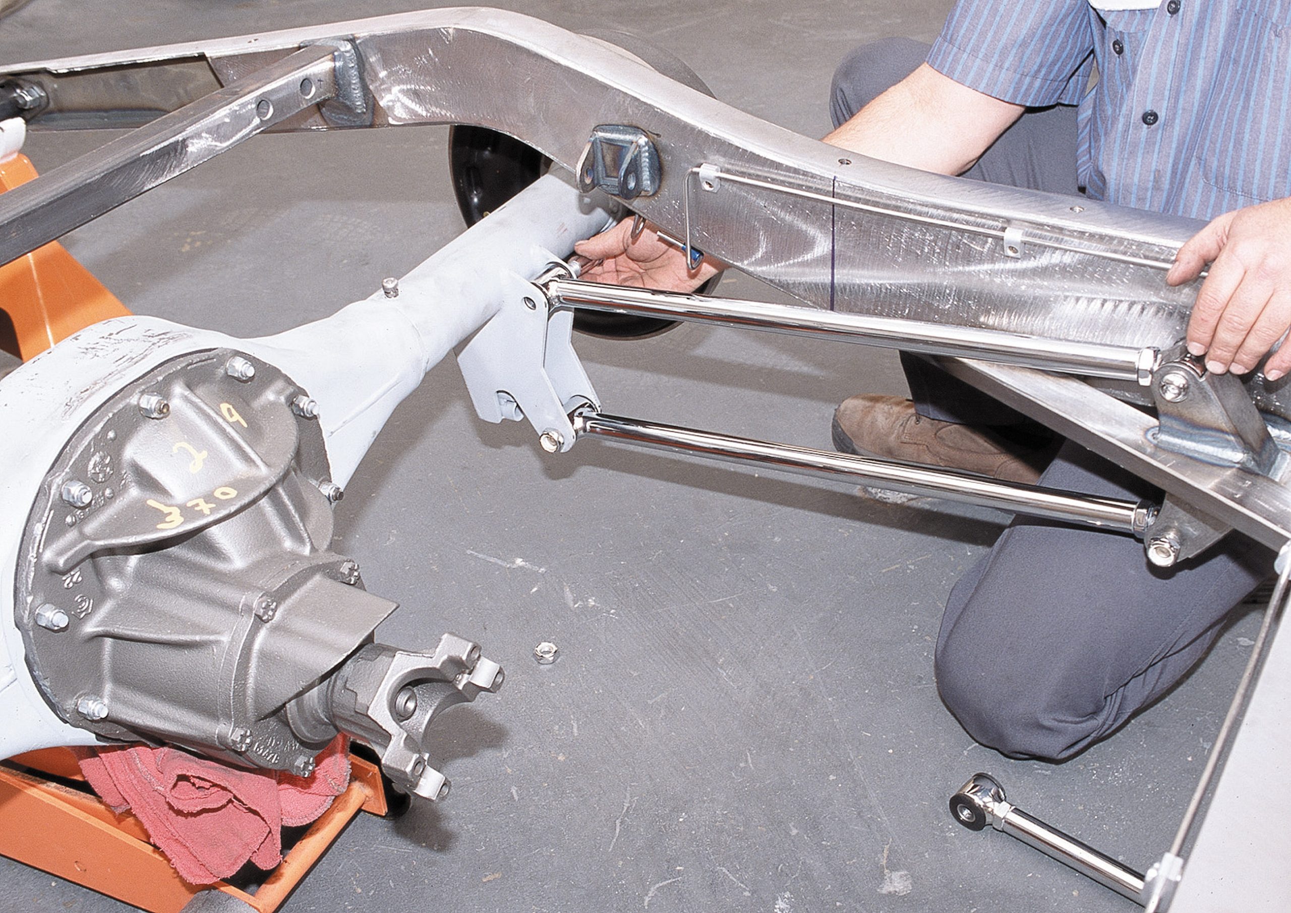
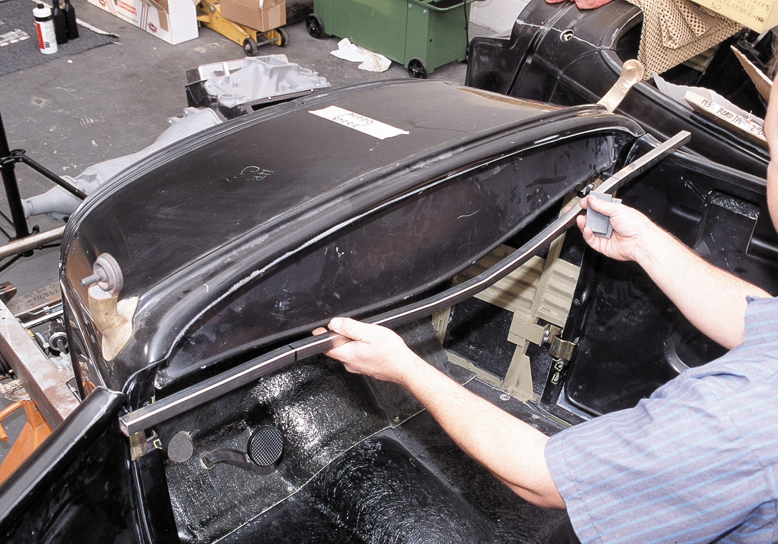
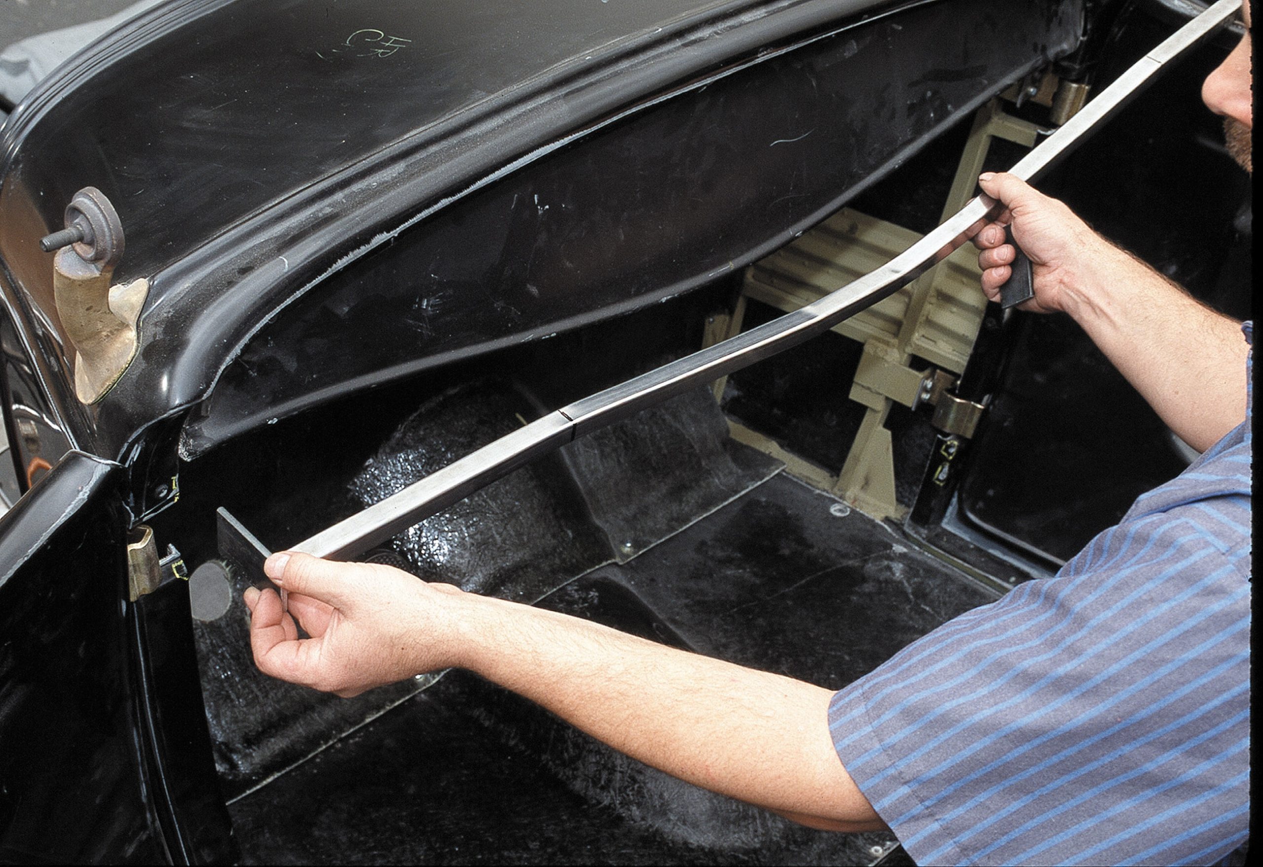
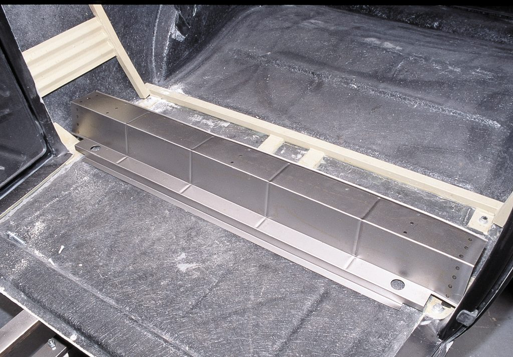
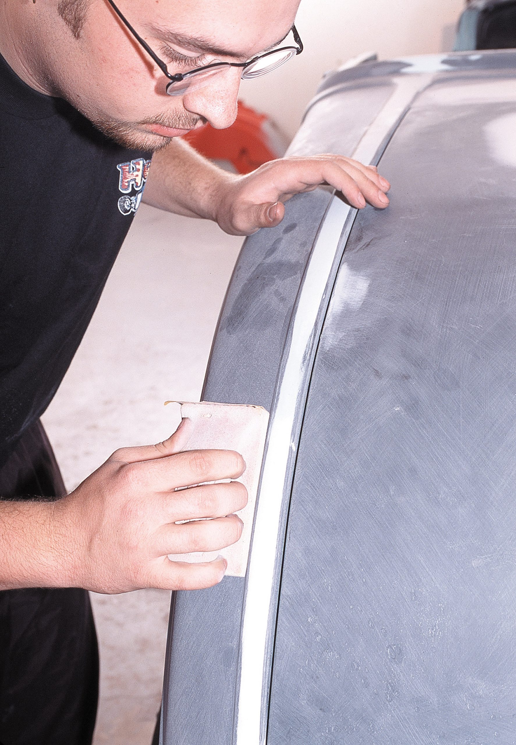
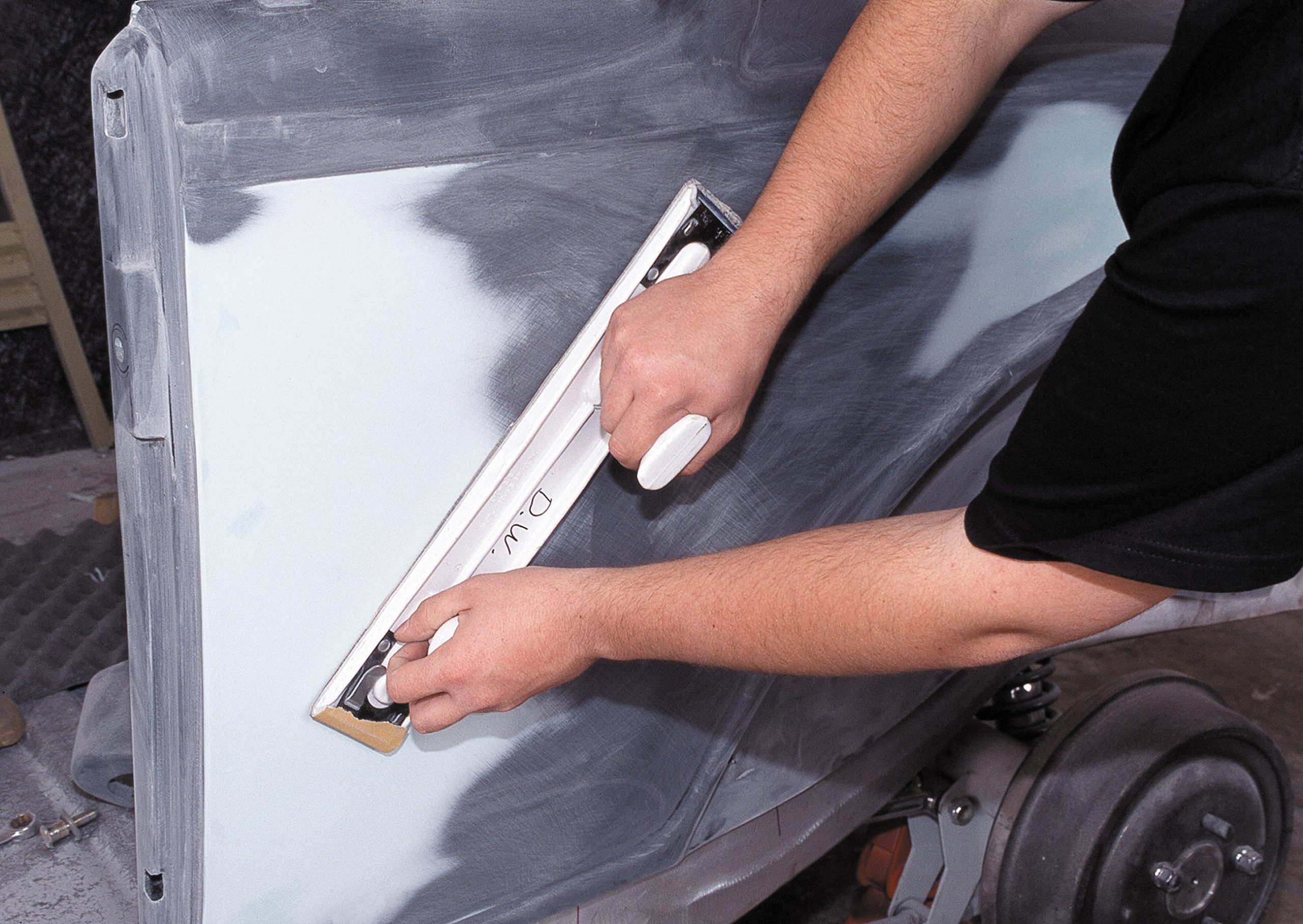
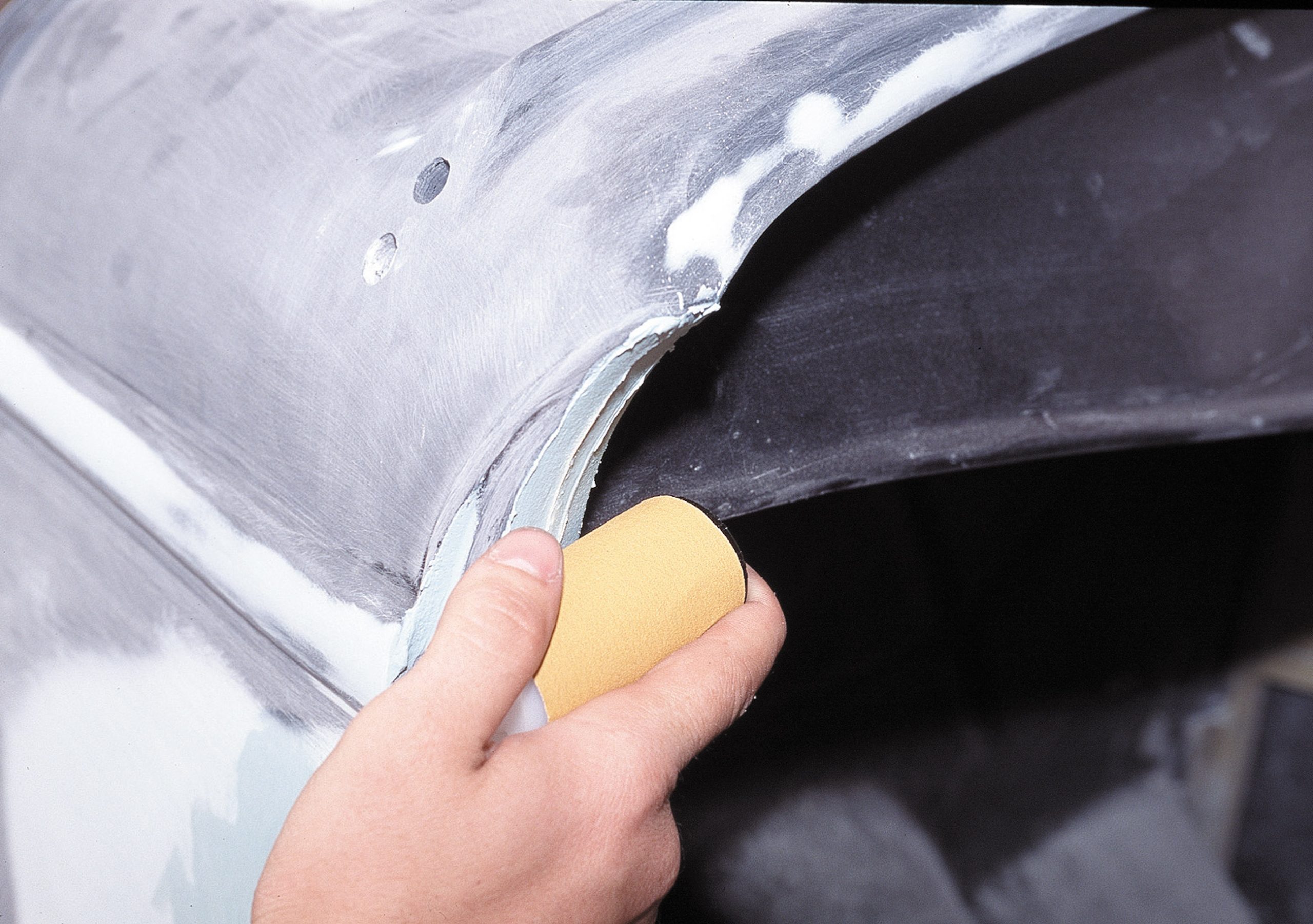
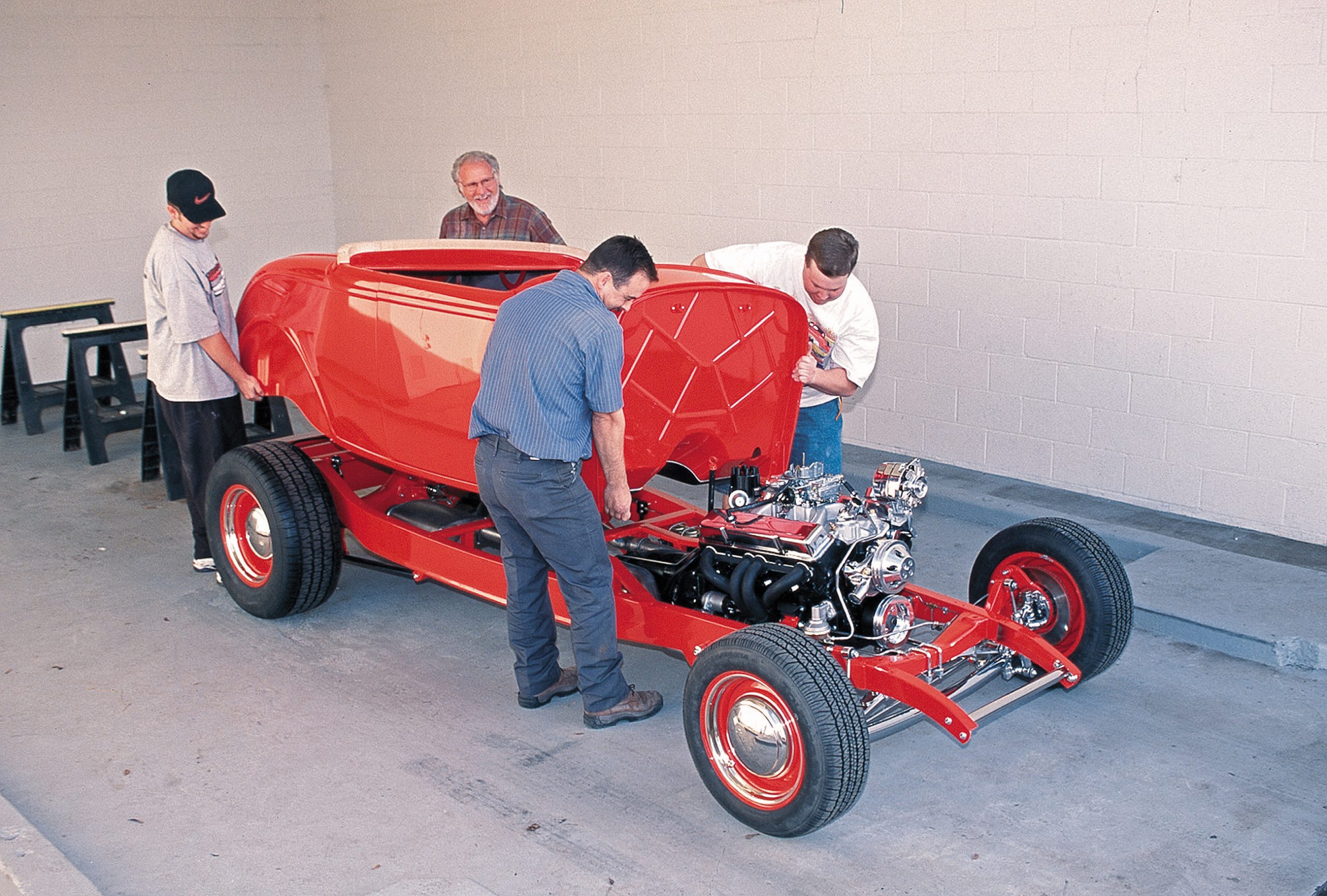
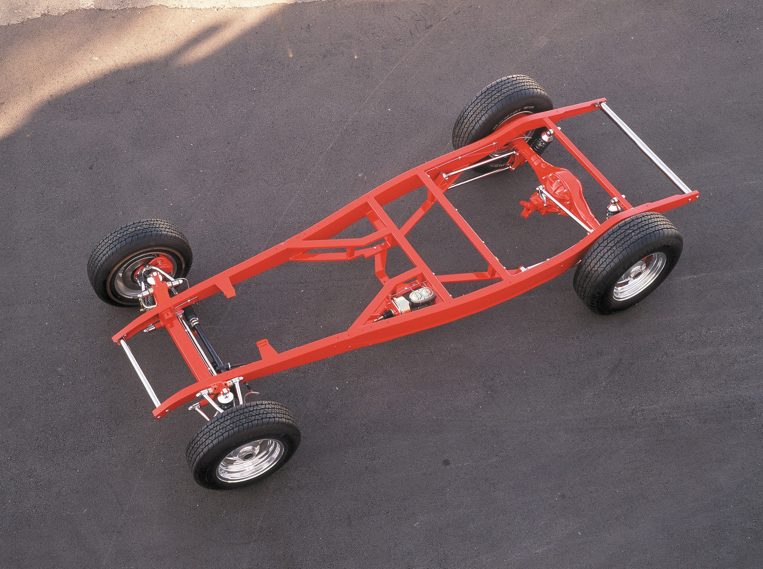
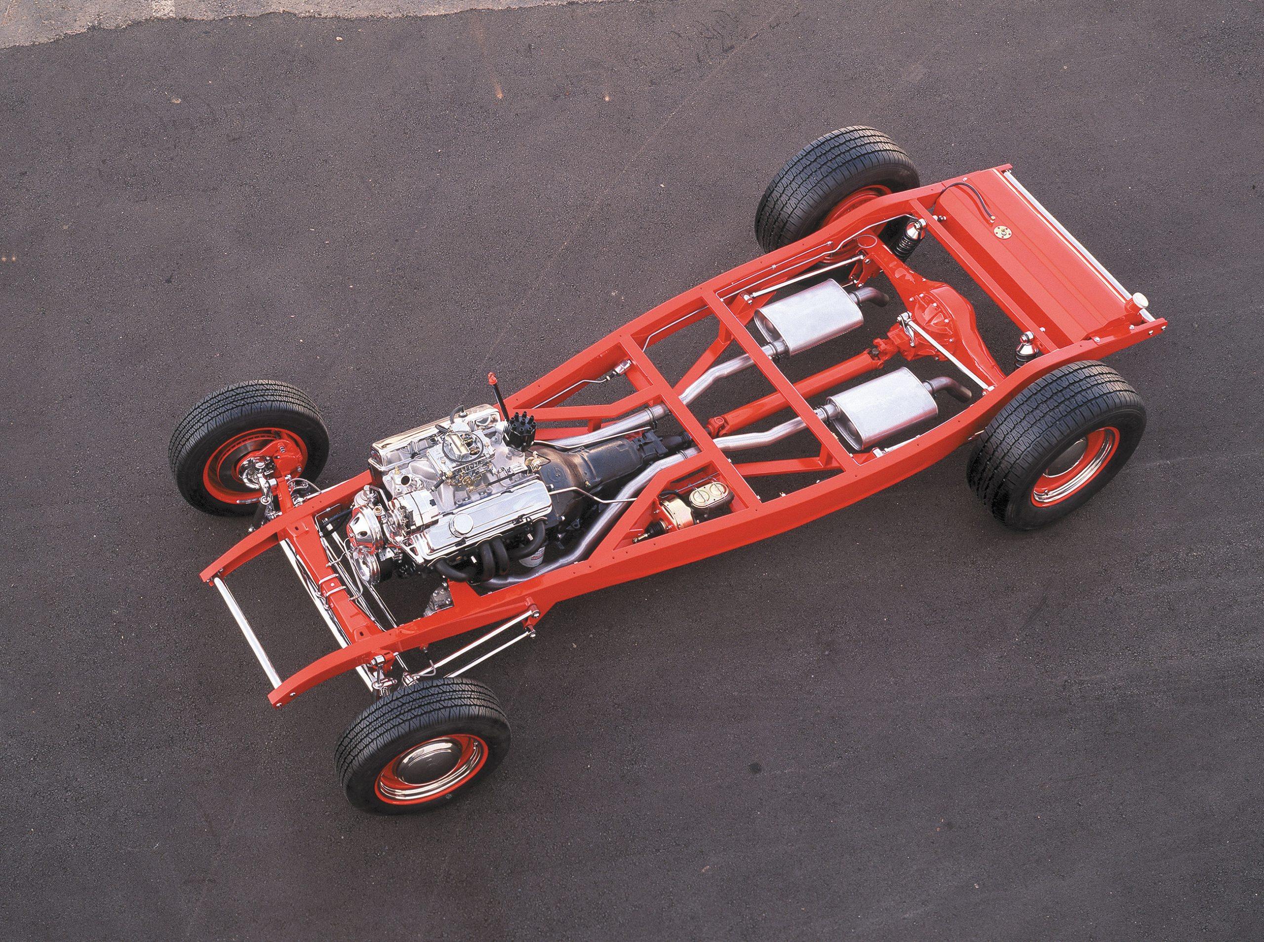
None of the following is meant as a step-by-step process as much as what the process would entail if you were to build a roadster like this one. For the most part, it is well within the reach of most street rodders with average or better mechanical skills and budget. We’ll tell you—in an effort to put all of this in the proper context so that you might better figure what your overall investment would cost—that this particular car was built at a shop and would be sold for around $40,000 when complete.
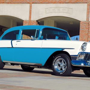
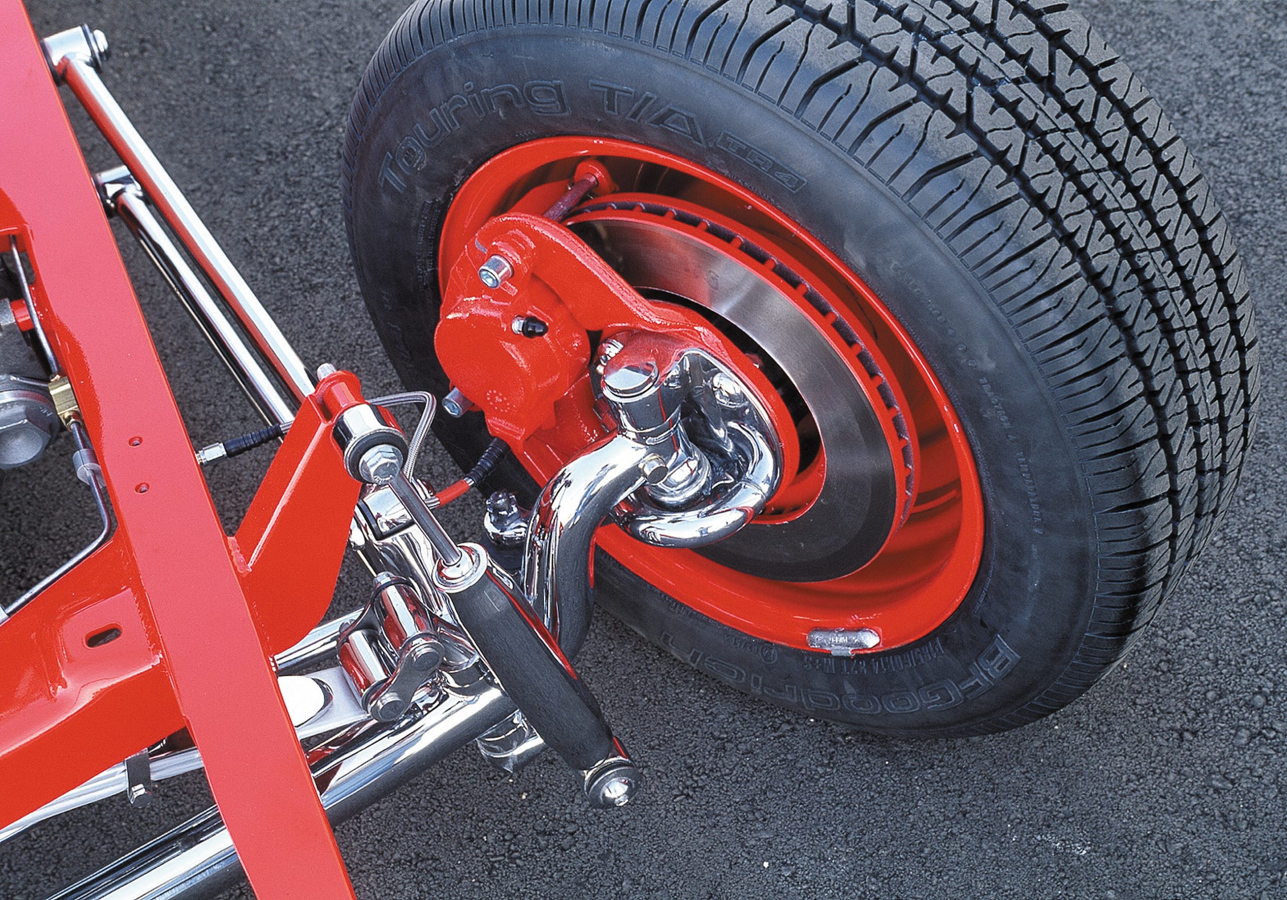
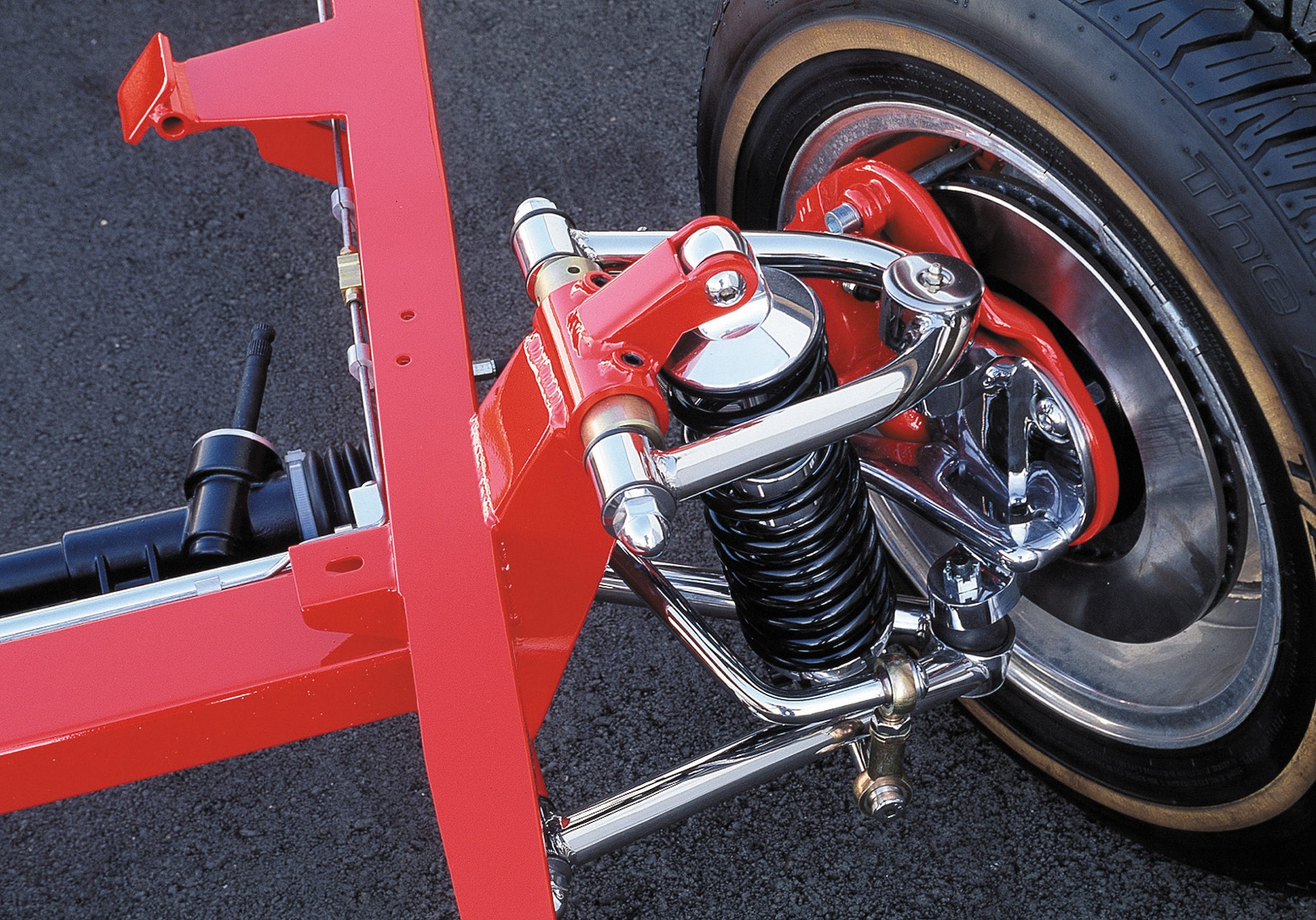
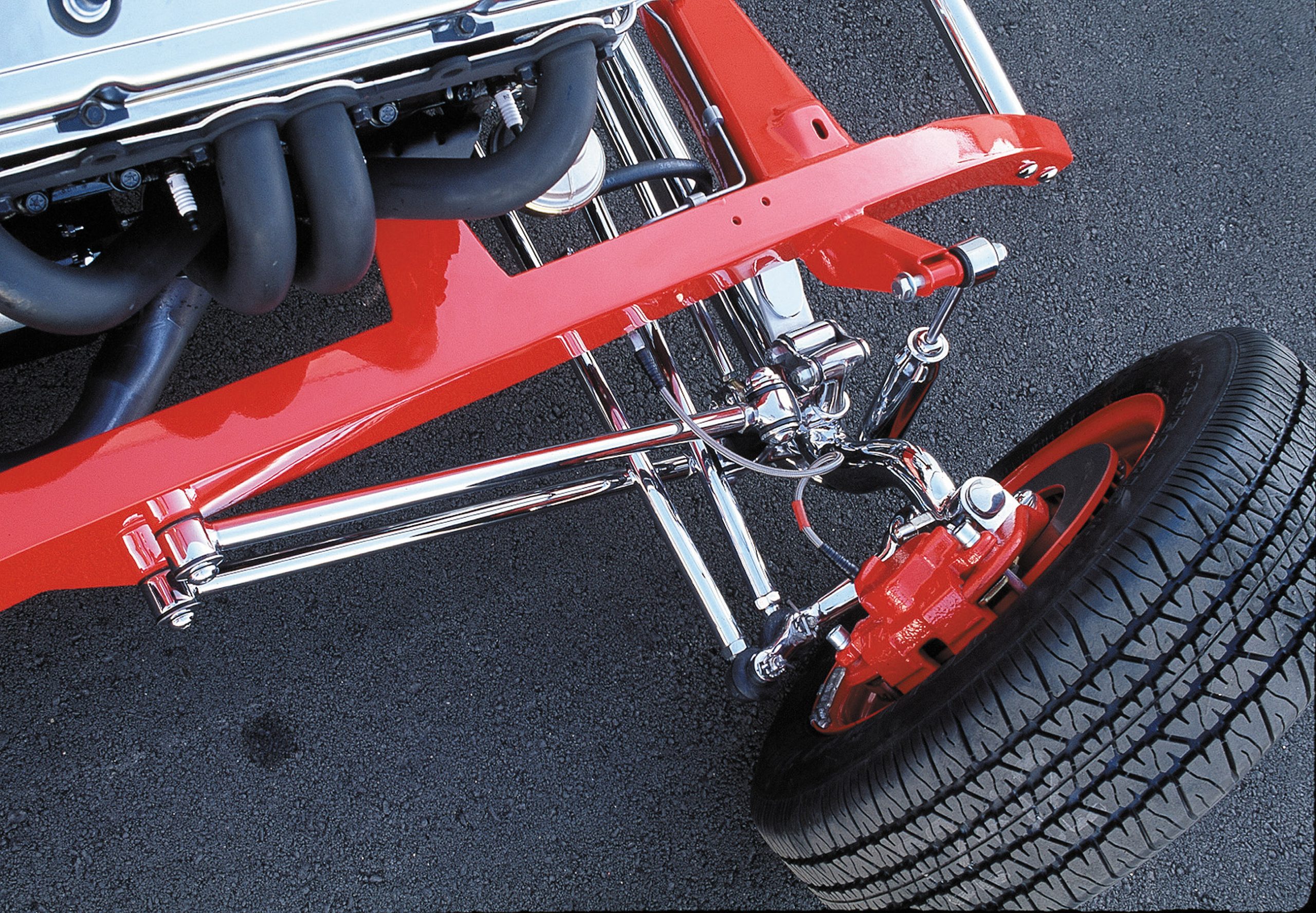
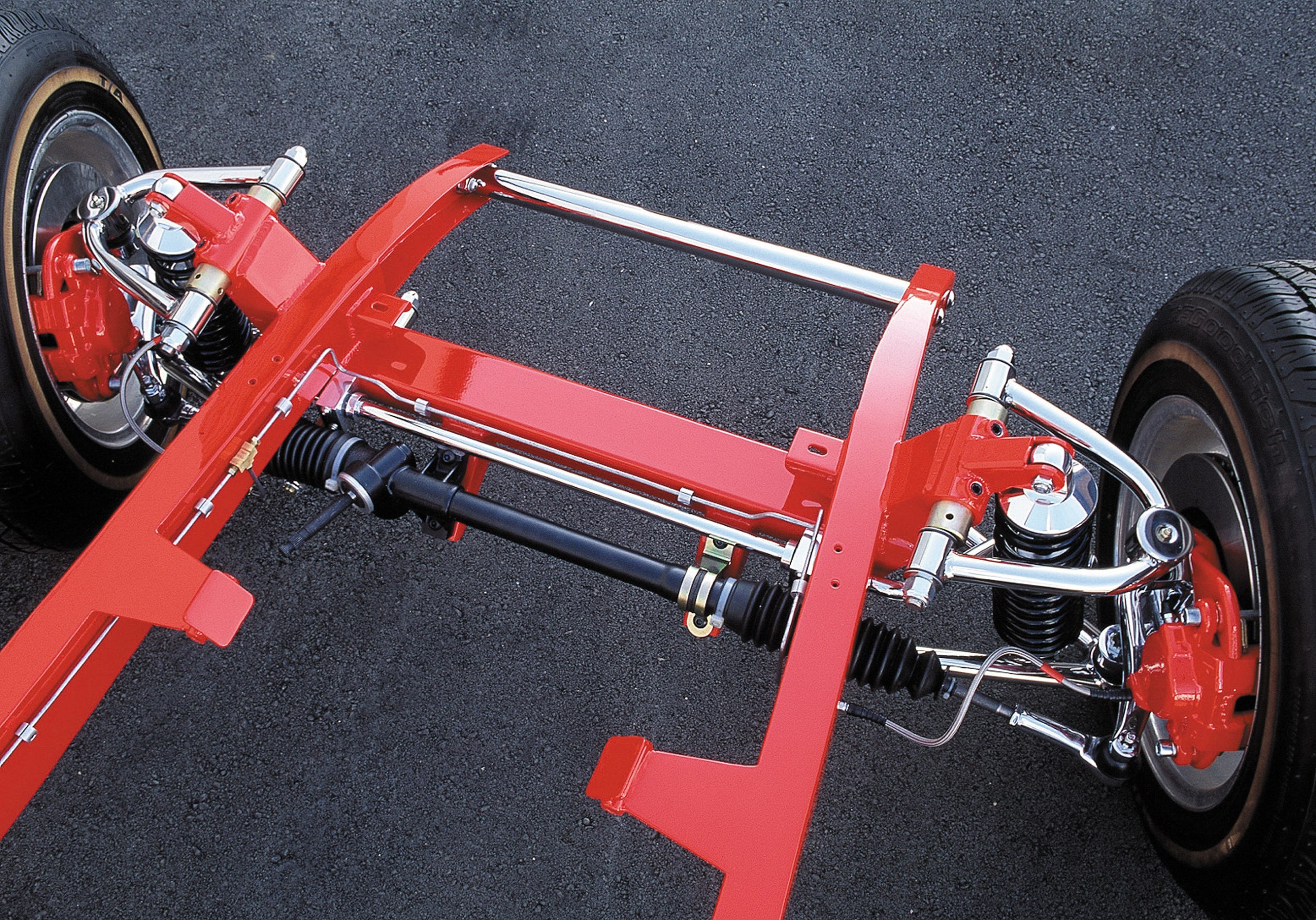
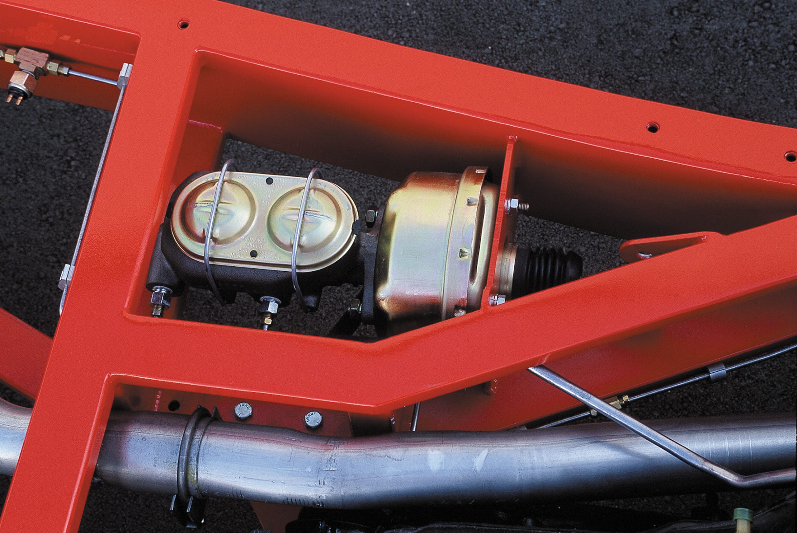
The Appeal of a Deuce Highboy Roadster
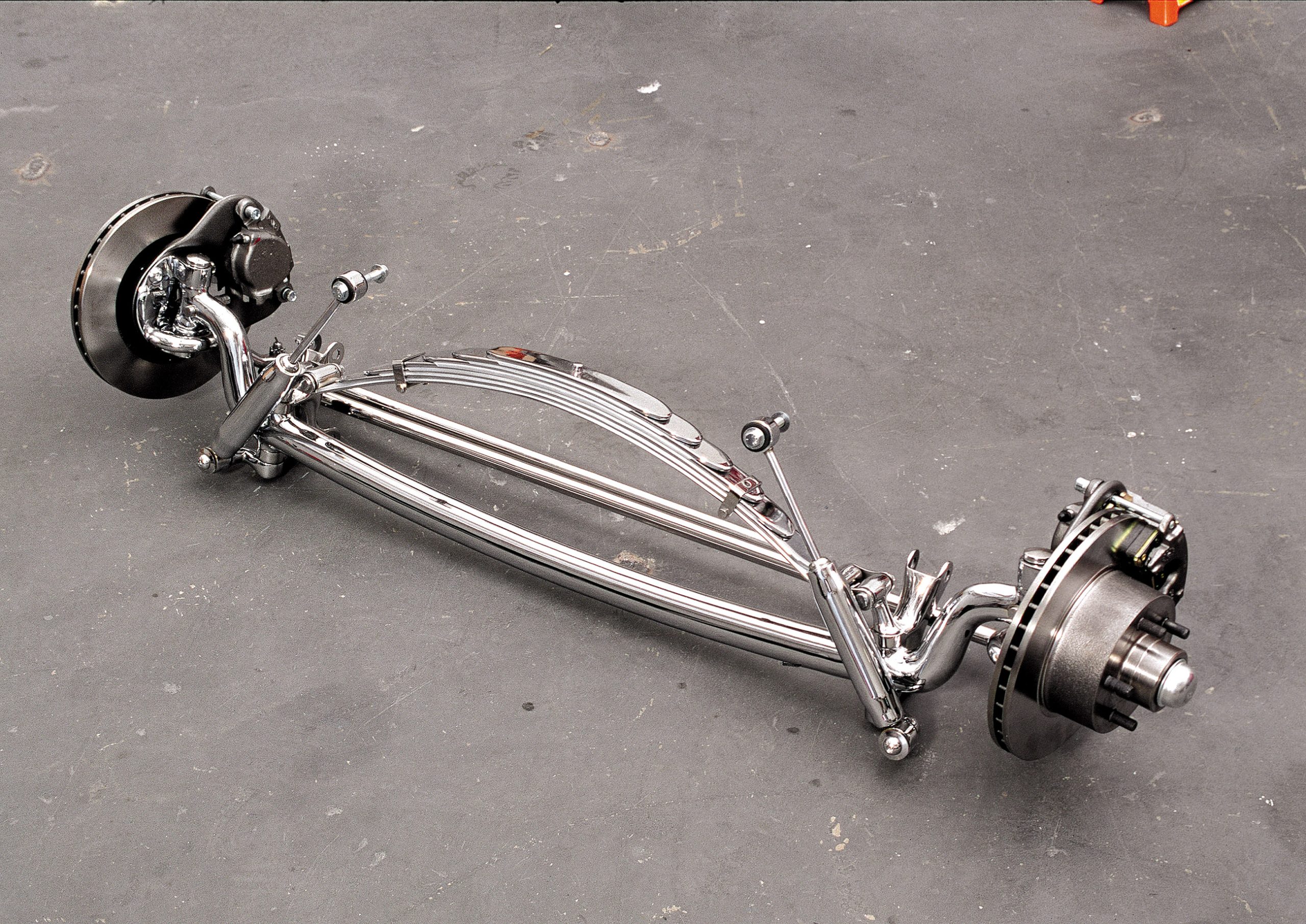
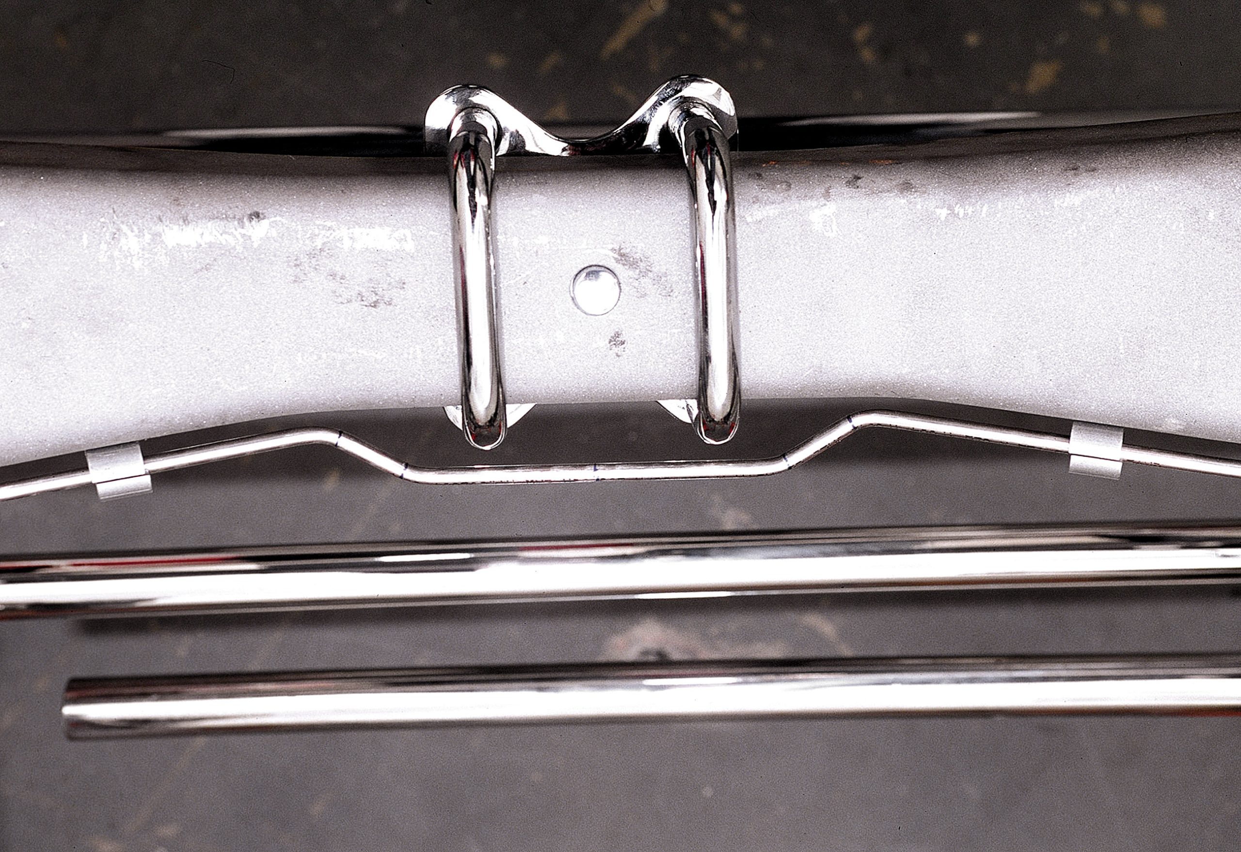
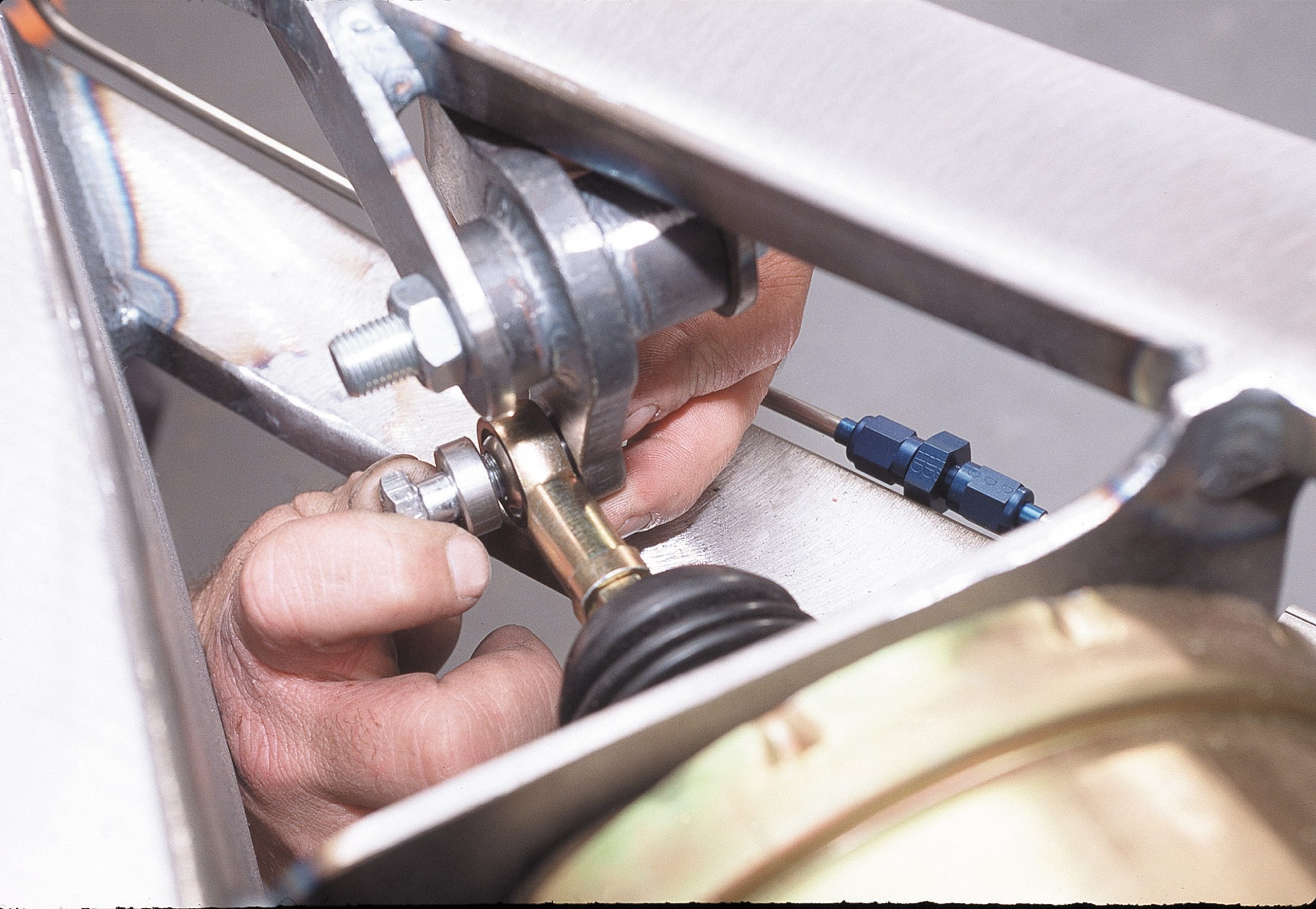
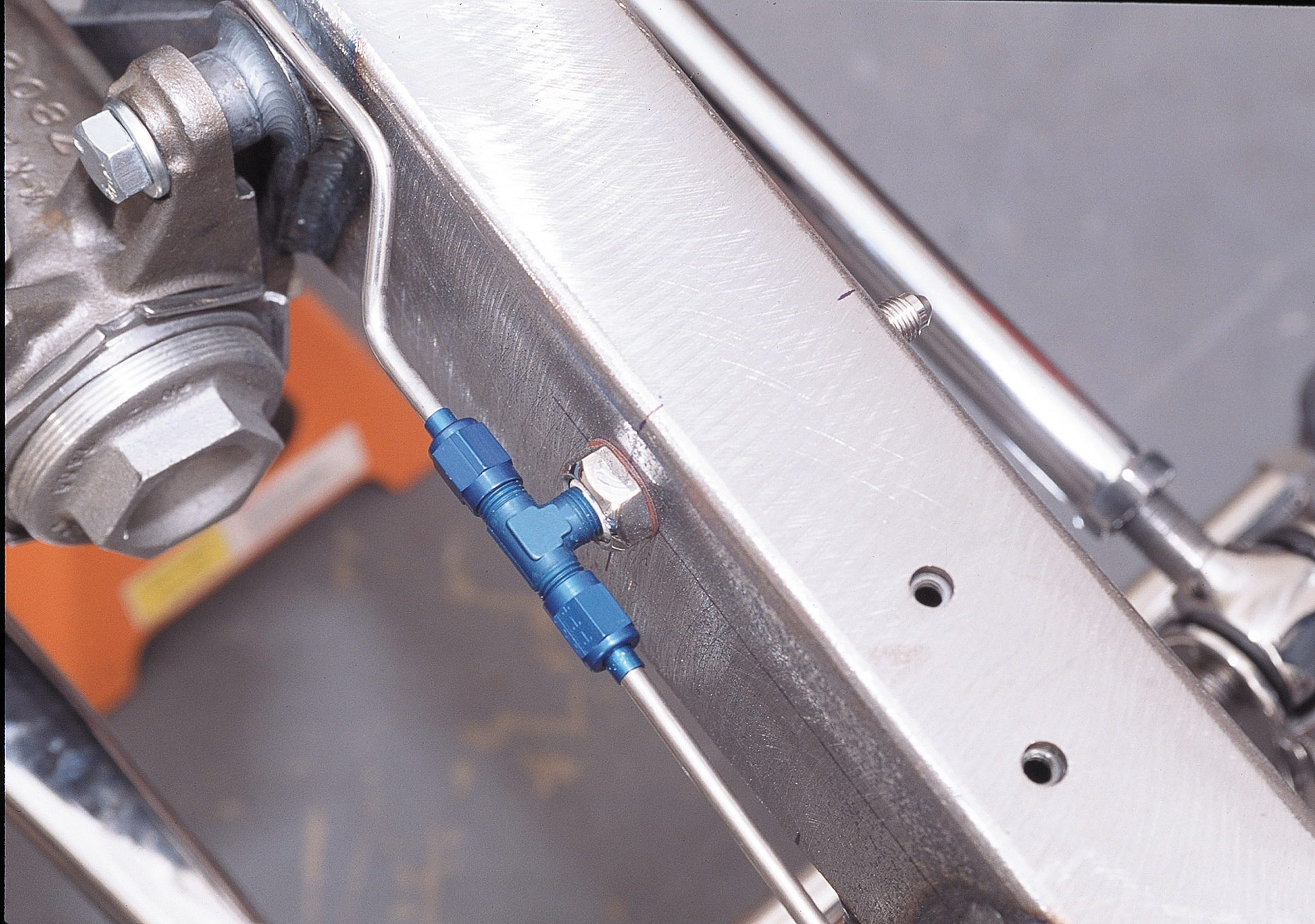
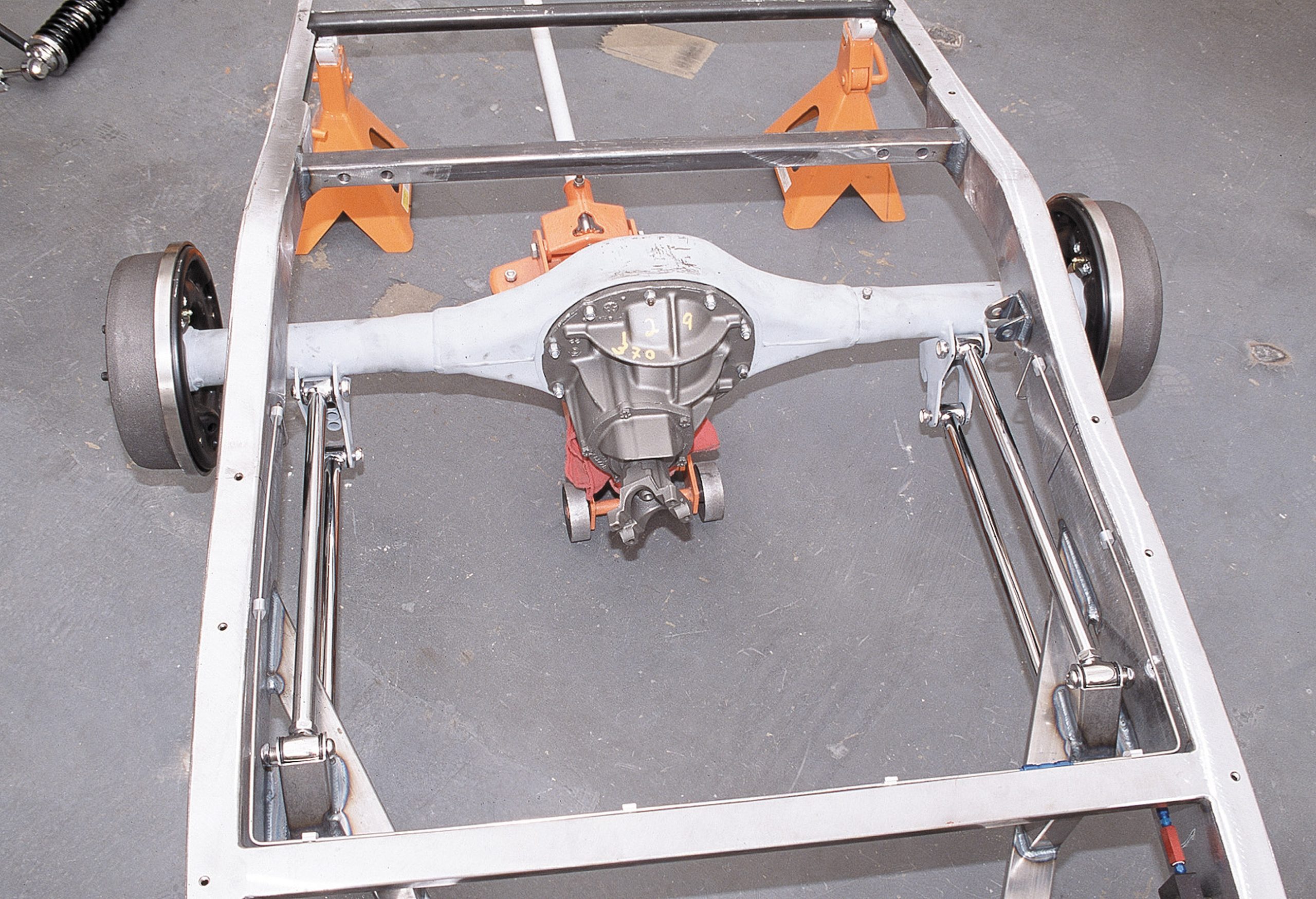
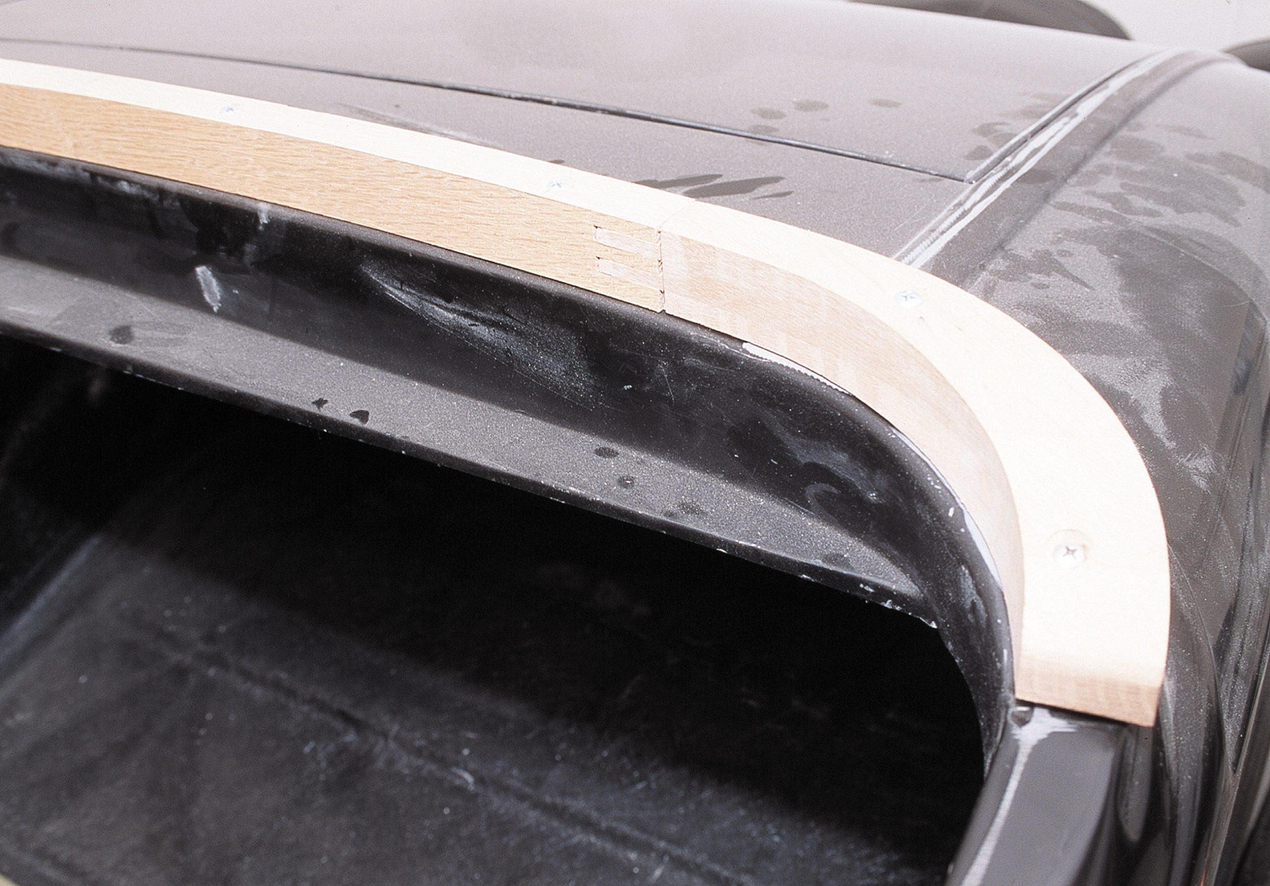
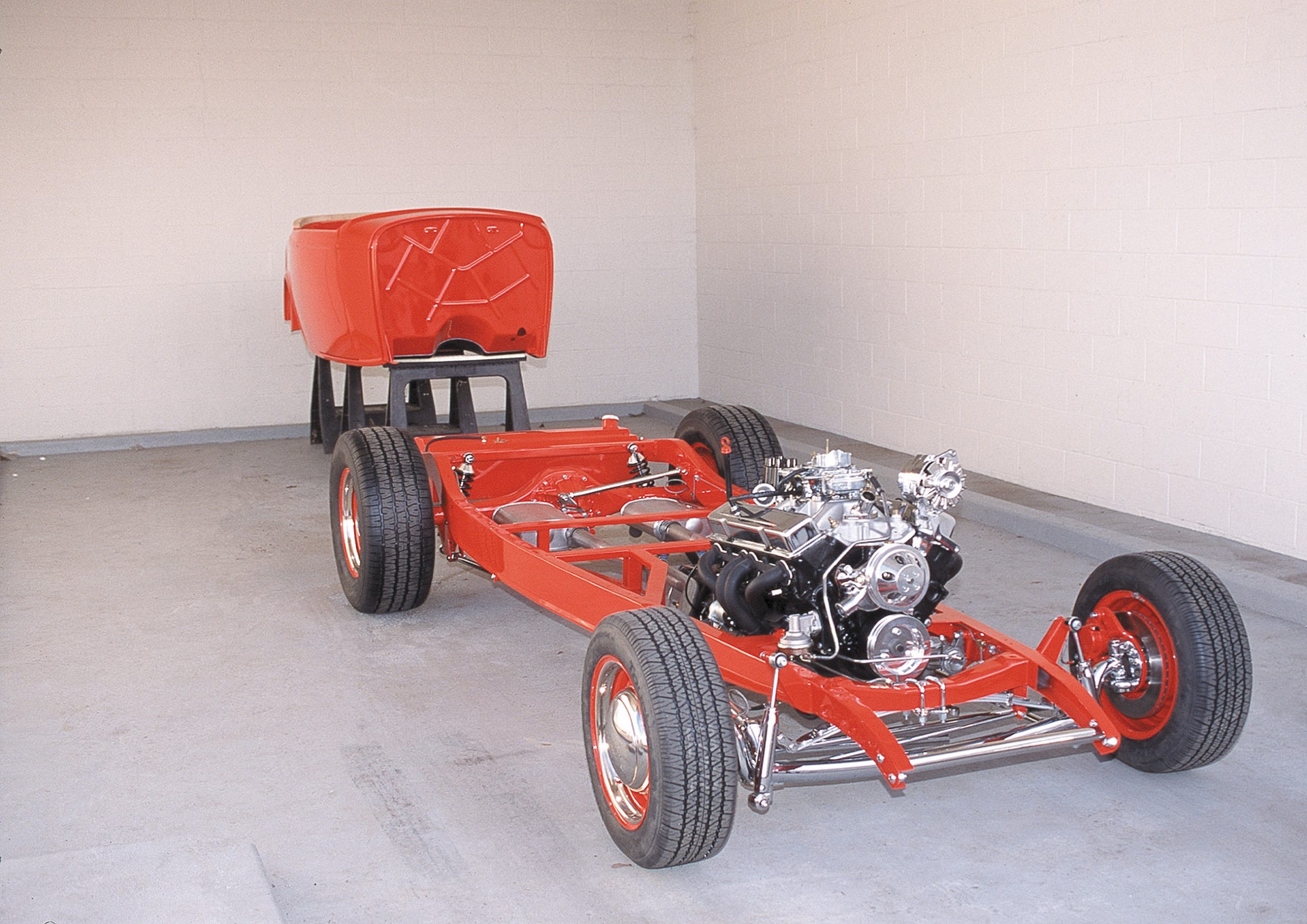
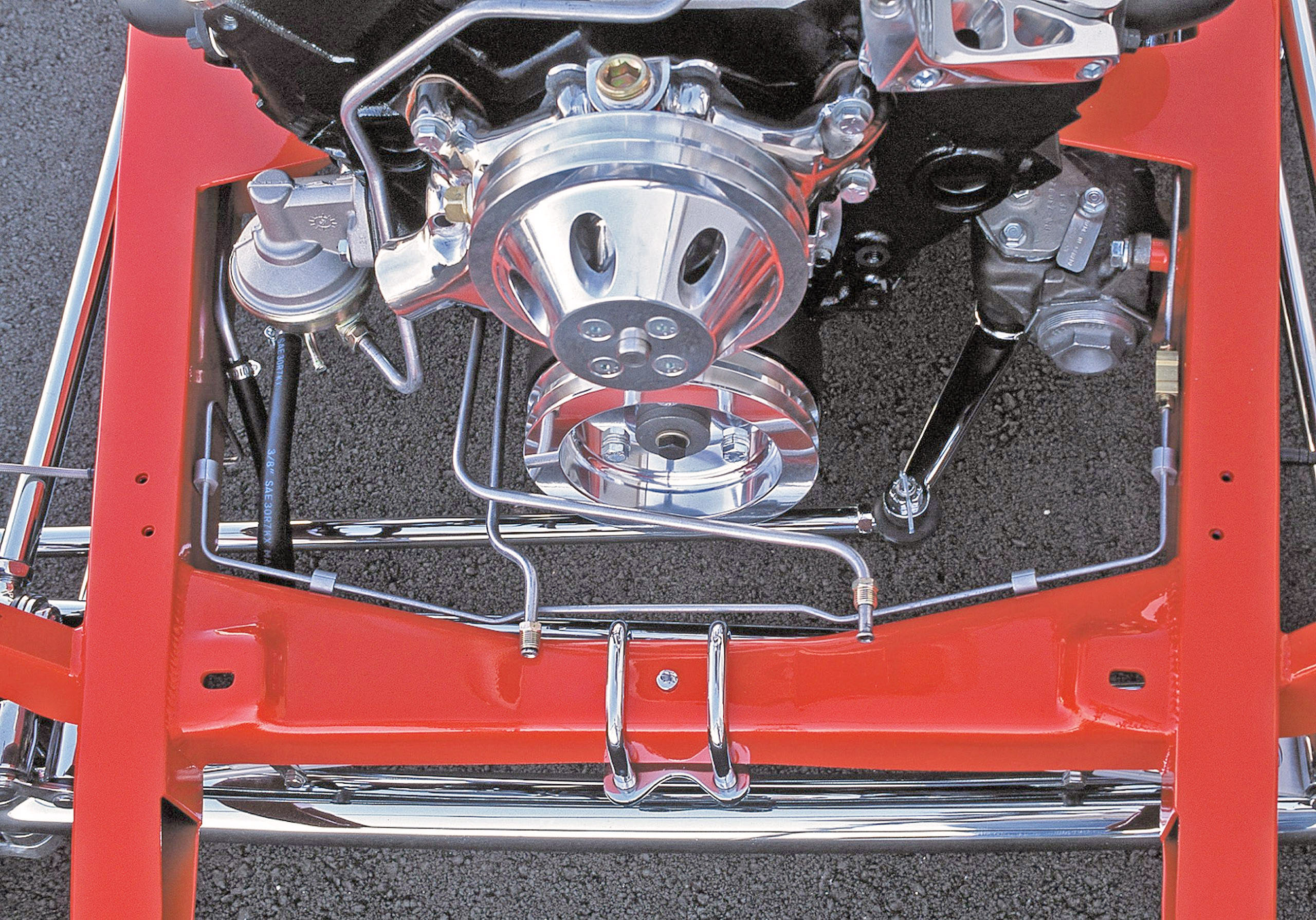
Certainly, there are more sophisticated roadsters than this one, but who’s to know the difference when you’re motoring through town behind the wheel of your very own Deuce highboy roadster? The attention to detail in this car is pictured on the following pages. You can be the judge, but I know that I’d be proud to drive it anywhere.
1. Pictured are the bare frame (background) and the assembled front suspension. As can be seen in the lead photograph, the frame and suspension package come in component form, not assembled.
2. The front suspension assembly is basically ready for installation. It is positioned by either a four-link or hairpin linkage and front Panhard bar.
3. Balancing the assembly on a floor jack will put it into position. An extra pair of hands will make the task easier and a lot safer.
4. The spring assembly is held into the front crossmember with a pair of U-bolts and spring clamps. Attach these first.
5. Once the spring is in position and its locating bolt is aligned with the crossmember, the U-bolts and spring clamps can be securely tightened.
6. The Vega-type steering box is held in place with three bolts attached to a well-gusseted frame bracket.
7. The steering box bracket tabs are drilled and tapped to accept the retaining bolts and lock washers. These should be tightened to secure the box to the frame.
8. The serrated Pitman arm is neutrally attached to the steering box shaft and retained with the appropriate retaining nut.
9-10. The cross-steering arm is attached to the Pitman arm by a tapered shaft on a tie rod end. The shaft is retained by a castle nut and cotter pin. The cross shaft attaches to the right front steering knuckle.
11-12. The drag link attaches both front wheels and is controlled by the cross-steering arm. The Panhard bar is the third link from the right in the photo.
13. The Panhard bar retains the front-end assembly in a centered alignment. Its heim joint attaches to the left frame bracket and the right side of the axle.
14-15. The upper bar of the four-link attaches to the batwing. The rod end is fitted with urethane and should be attached first to the axle. Rough alignment adjustments can be made, but final adjustments will be made more accurately once the front and rear assemblies can be triangulated. The normal castor angle should be approximately a 5-degree tilt toward the rear.
16. The upper and lower four-link attachment is made at the frame. A soft mallet may be required to insert the bolts while aligning the bolt holes.
17-18. Once all of the components are in place, the attachment points and rod ends can be tightened. Eyeball or use a measuring tape to pull everything into alignment, but only snug the adjustable points as final adjustments will be made at a later time.
19-20. Mount the front shocks ahead of the front axle. Attach the upper shock eye by inserting a bolt through the shock-mounting bracket. In this case, the shock mounts toward the front of the shock-mounting bracket.
21. The lower shock installation utilizes the spring perch bolt and the lower shock bracket that bolts to the bottom of the through-the-axle spring perch bolt. The shock attachment stud is positioned toward the front. Check for proper shock clearance and ensure that there is no binding throughout axle travel.
22. The brake pedal assembly is held above the frame in a relative location to where it will be installed. Brackets welded to the frame accommodate the bushed collar.
23-24. A heim joint is threaded onto the master cylinder actuator arm, located directly in front of the power booster. The booster assembly itself mounts directly to a sturdy attachment plate welded between the crossmember structure.
25-26. The brake pedal assembly is slid into place between flanges and is attached to the frame mounting brackets via a through-bolt. This enables the brake pedal to travel freely through its fulcrum.
27. The heim joint mounted on the actuator rod is then attached to the lower pivot arm, which enables the brakes.
28. The brake line plumbing is an area that requires time and patience and cannot be rushed. Precise measuring of bends, flares and turnouts is important for a neat, finished look, and it’s also necessary to fit all the components within small spaces.
29-30. Here’s a typical example of cramped quarters with lots of hardware, all neatly fit together. The AN fittings must be flared and bent at precise lengths for proper fit. The brake switch and proportioning valve are neatly aligned and fit between proper bends so that the lines continue along their path to the next juncture.
31-32. Special factory-fit banjo ends are attached to braided stainless lines that connect each brake caliper to the fittings mounted to and attached through the frame. A wide variety of fittings are available for unusual installations or routing requirements.
33. Carefully route outside of the frame braided lines so that they do not interfere with moving suspension members. Enough slack should exist so that the lines are not bound at full travel.
34-35. At the rear are options in hard-mounting the brake lines. Here a tab is used along with a short bulkhead fitting that is attached on both sides of the tab. Careful attention must be paid while cutting and compound-bending the line so that the flare seats squarely in the fitting.
36. The soft braided line from the rear backing plate is then attached to the through-the-tab fitting mounted to the frame. Double-check for proper line slack and no interference.
37. When considering the cost of the project, a solid rear axle housing is tough to beat on all counts. Here a complete Currie axle assembly is ready for installation. Assembled units are available, or you can save the labor by purchasing each individually, including a pre-assembled third member of your gear choice.
38. With the help of a floor jack or some friends, place the rear axle assembly under the frame in its relative position. From here, the suspension members can be bolted in place without having to drag the chrome connecting arms across the garage floor.
39. The upper and lower four-link bars should be mounted loosely to the axle brackets already welded in place on the housing tubes. If you do not order the axle housing with the frame, these brackets will be needed, along with the recommended width of the axle tubes from one backing plate flange to the other.
40. Frames will vary, as will the design of certain components. Rod end bushings are used to properly space the front mounting brackets and firmly attach the suspension arms without binding.
41-42. The upper and lower arms can now be attached to both the forward and axle-mounted brackets. Attach the arms and move the rear axle assembly within the frame as required.
43. As illustrated, the housing is not properly centered here. Move the housing side-to-side accordingly, and bolt the forward arms in place.
44. With the housing positioned in its proper location, the attaching bolts will easily fit through the brackets. Should they require a bit of coaxing, use a soft mallet and install the self-locking attachment nuts.
45. The rear installation is not quite complete. While it is roughly centered within the frame, it now requires a centering device in the form of a Panhard bar to keep it there.
46. A bracket from the manufacturer is mounted to the frame. Here is a look at the left frame attachment bracket prior to frame component assembly.
47-48. With the axle housing assembly installed, the housing bracket for the centering device can be bolted in place. Here is the center attachment point for the Panhard bar. This is how housing alignment is retained within the frame and bolted to the third member. The adjustable bar will then be inserted at both brackets.
49-50. Install the bar and adjust the rod ends so that the bar will fit between the brackets. Eyeball the position of the housing, adjust the bar accordingly and insert the mounting bolts.
51. Using a tape measure, split the difference (from side to-side) between the backing plate and the outside framerail. Adjust the Panhard bar to retain these measurements. The housing should then be centered.
52. The completed suspension linkage is installed, along with the four-link and Panhard bar. Next comes the suspension.
53. The simplest and most cost effective (not to mention good-looking) method of suspending a street rod is with the use of coilover shock absorbers. Varying spring rates allow for better ride quality and ride height adjustment. Some shock valving is adjustable, and so is the spring-installed height on the shock itself.
54. The rear crossmember allows you to vary the angle at which the shock is mounted. The innermost upper mounting position allows the shock to operate at more of an angle and is believed to better dampen the axle arc within which the housing seems to operate. In the outer location, the shocks are more perpendicular to the axle housing.
55-56. The bottom shock-mounting location is adjustable by selecting one of three mounting positions. This will provide you with adequate ride height. Position the top of the shock on the mounting shaft, and raise or lower the axle housing where you believe it sits correctly. Mount the bottom of the shocks accordingly. Minor ride height adjustment is obtainable at the shock/spring should minor adjustment be necessary.
57. With the housing-to-frame clearance adjusted to a height that you feel is a good beginning point, bolt the shocks in place and tighten them securely.
58. The rearend assembly is completely installed, adjusted and centered. During the actual construction, you will go through this process twice, once for fit and again for final assembly on a painted frame. We will show you the final assembly without going into the bolt-up procedures.
59. Little tricks during the construction will keep you from repeating steps. Here you can see alignment marks made to the frame and body so that each time the body is separated from the frame, it goes back to the same place.
60-61. Wescott’s bodies require an under-dash metal stiffening support to be mounted to the cowl structure. This provides improved dash support and a place to mount the top portion of the steering column. Square tubing is bent to the shape of the lower dashpanel. Its length is measured in place, and attachment tabs are welded to both ends. The crossbar is then welded to the metal cowl structure, completing the support.
62. A seat attachment mounting brace is installed to the floor. This bracing will vary depending on the type and style of interior seating selected. Check with your body manufacturer to see what is available prior to fabricating something that you don’t need or is less expensive and easier to purchase. Requirements will vary here.
63. The wood bow attached to the body will accept a convertible top. If no top will be used, this element can be eliminated, and the body can be manufactured smooth, requiring no additional fabrication or fill work.
64. The body attachment holes are drilled and tapped in the framerails. Transferring these alignment holes to the body can be done by making tapered pins or scribe dowels that screw into the frame holes yet protrude just above the framerail. The Wescott’s body comes with mounting pads molded into the body with attachment holes located at the four corners. Lower the body over the four locating dowels and onto the pointed inserts that will mark the gelcoat, allowing you to accurately drill each body hole location.
65. For a proper and sturdy fit, the body must rest flat on the framerails. This often requires shimming the body to the frame. Automotive front-alignment shims are used so that the door alignment is satisfactory. Pictured is an illustrated note depicting shim thickness for each pad location so that this tedious job only has to be done once.
66. A handful of automotive front-end shims of varying thicknesses are used to properly mount the body to the frame.
67-68. The four corners of the body mounting locations usually require shimming. To determine the thickness of the shim, loosely attach the front bolts and begin checking them. Look for body revel alignment and make sure that the doors open and close once the body is tightened to the frame.
69-70. The transmission tunnel panel must be aligned and fitted. Trim as necessary while fitting it into place. Once installed and fit properly so that it lays flat into the existing floor opening, attach it to the floor with screws.
71. Through-holes, such as the steering column hole and brake pedal holes, should be carefully and precisely positioned and cut to proper size. Excessive clearance is not desirable as you will see it in the firewall area, not to mention experience excess road noise and water.
72. Once the body has been fit to the frame and all mounting hardware is fit to the body, it is ready for hours of block-sanding, filling and more block-sanding. All fiberglass parting lines are eliminated using a sanding wheel or rough sandpaper mounted on a carrier of some type and cut by hand. Any obvious irregularities are filled with body filler and sanded. Sanding carriers can be made and/or purchased. Pictured are but a few of the commercially available and homemade versions.
73. Smaller curved areas can be best approached using a shorter, pliable carrier that will contour to the existing bodylines.
74-75. For larger, flatter areas that are still too small for a long board, a homemade paper carrier using a cut length of 2×2 wood works well. The sanding pattern should be done with the wood turned toward one direction and altering both the tool and the sanding direction 90 degrees.
76. A flat, 1/4-inch-thick piece of hard sanding rubber works well around revels, in door edges and in any area that requires getting into small crevices. Like all other sanding techniques, begin the process by first wiping the body to remove any old wax, and begin wet-sanding using 80-grit paper. In stages, you will eventually be blocking with 200-grit paper.
77-78. Long boards are available in varying lengths and in both rigid and pliable face. Choose one that best suits your needs and covers the greatest amount of area. Again, reversing directions and sanding angles provides for a smoother, flatter surface. The sanding lines will also provide better grip for the primer/filler to adhere. DuPont offers a wide variety of products for most any application or specific job. Like all painting and body materials, using more lighter coats will result in a no-blemish finish that provides a flat luster.
79. Edges and corners are particularly a chore as you tend to sand off all the material. Build up the area lightly, as with the rest of the body, and sand using light pressure. Here an edge is being finished using glue-backed paper applied to a curved carrier of wood or plastic. Even a well-finished fiberglass body will require a full week of flat out block-sanding, filling and more block-sanding. Ultimately, using a sanding coat of contrasting fogged-on color will enable you to achieve a smooth, flat surface.
80-81. Here is a front view of two very different front-end systems using the same basic frame. The dropped front tube axle, similar to the one used in this buildup, is the most straightforward and inexpensive of the two. The tube-type IFS systems are available in a number of configurations and provide an improved overall ride. They are more expensive, but they look better.
82-83. A rear view of the same two front-end systems shows a cleaner, less cluttered appearance with the A-arm suspension. For the IFS, the steering input comes from a rack-and-pinion design, available in both normal and power-assisted versions. This eliminates the cumbersome worm gear steering box and all the necessary suspension and steering rods. The rack mounts neatly behind the front crossmember.
84. Shown are detail photos of the finished master cylinder and brake booster installed compared to the earlier unfinished installation photos. The detail and contrasting colors are nicely done. The brake fluid reservoir uses a front and rear dual system and snap-on filler cap and is accessed through a removable panel in the floor. Extreme care must be exercised when handling brake fluid as it is highly caustic and will remove paint.
85. This is a similar brake line area to the one shown earlier. Now you can better appreciate the attention to detail that was mentioned. Note that this installation, while much the same, utilizes conventional brass fittings rather than the more expensive AN design. The AN-type fitting selection offers a wider variety of choices for a more custom installation. Except for the more bulky-looking fittings, the installation shown here looks just fine.
86-87. The finished rear axle and suspension installation are shown in detail with a noticeable improvement over the buildup photos. Once the exhaust system is installed, note the closeness of the components. All of this should be taken into consideration during the fit-up phase, which is the primary reason why this step is so vital to the overall finished look of the project.
88. So that all adjustments can more easily be accessed, now would be a good time to square the chassis and suspension so that the vehicle is tracking straight and moving components in parallel. Select measuring points to each corner of the frame, extremities of the chassis and side-to-side duplication of the wheelbase. Measure front to back and from side to side, and triangulate front to rear, going left to right and right to left. Each of the corresponding measurements should be within 1/8 inch. To arrive at exact measurements that are repeatable, adjust the suspension members in small increments and re-measure each time. Once squared, the chassis will roll freely as each wheel is in alignment, front to rear and side to side, with one another.
89-90. The chassis void fills up quickly once the exhaust is installed. The completed shots looking forward and from above clearly illustrate the careful planning, measurements and fitting of all the components. If any should touch, a resulting rattle will forever plague the vehicle operation until it is remedied. It is far easier to fix things now than later, when even more parts and pieces will be in the way.
91. The fuel tank is mounted in its stock location and finished with a stainless rear crossbar that bolts within the left and right framerails. The rear of this tank will be exposed. Another method is to mount the fuel tank in a vertical position behind the rear seat toward the front of the rather limited trunk area, reducing usable space even further. Companies, such as Tanks, sell a variety of fuel tanks for Deuces.
92. The cleaner appearance of the IFS front-end installation is one of the reasons why this system is so attractive to potential street rod builders. Not only are they popular, but they also perform better in a wider variety of road conditions. There is roughly a $400 price difference between a solid axle and a typical IFS system.
93. Here’s a completed front view of the old tried-and-true solid axle design. Although busier to look at, the basic system is quite fundamental in design. Road-handling characteristics are good, but not quite equal to that of a well-designed and properly installed IFS. The small-block Chevy engine nestles neatly between the framerails. Here block-hugging tubular headers and the drive accessories are mounted in place.
94-95. To place the body on the frame, you’ll need some help from a few friends. With a person at each corner, slowly walk the body over the rear of the chassis until it closely aligns with the mounting holes in the frame. The closer you can get to this location, the better your chances of keeping the paint in place will be. Once it’s down, you can proceed with the mounting procedure explained earlier.
96. Once you have chosen a radiator, it can be temporarily mounted to the front crossmember. As the surrounding body components are fitted around it, including the hood, you will have to adjust the upper positioning rods to achieve an ideal fit.
97. This is the fully assembled IFS frame, showing the whereabouts of all components integral to the frame and chassis. The engine, drivetrain, exhaust system and fuel tank will have no problems filling the exposed voids.
98. Here’s the completed chassis and frame showing everything, including the automatic 350 transmission and driveshaft. This is an unusual shot that rarely gets seen from this angle. It helps you appreciate the work and detail that go into making a basic street rod not so basic. Of course, you can pay for the labor to get this attention to detail, or you can save the money, upgrade component selection and spend the hours detailing it yourself. This is one sizable contribution to maintaining the least amount of investment in your home project. Good luck.