TheAutoBuilder.com

CIMTEX SUPER CAMEO: PART 6

Fabricating Engine and Transmission Mounts and the Driveshaft

Author

Picture of Bob McClurg

Bob McClurg

Story and Photography

…continued from Part 5

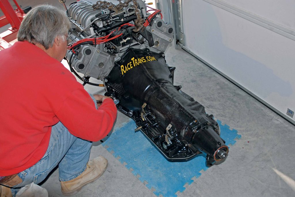
In Part 5 of our Cimtex Rods Super Cameo buildup series, we covered the actual building of our GM 4L80E electronic overdrive transmission, which will be backing up the Super Cameo’s Powerdyne twin-supercharged Corvette ZR1 engine. Also discussed were the tricky transmission electronics and the CompuShift electronic control module required to make this unholy alliance work. 

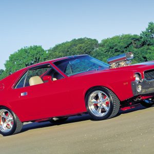
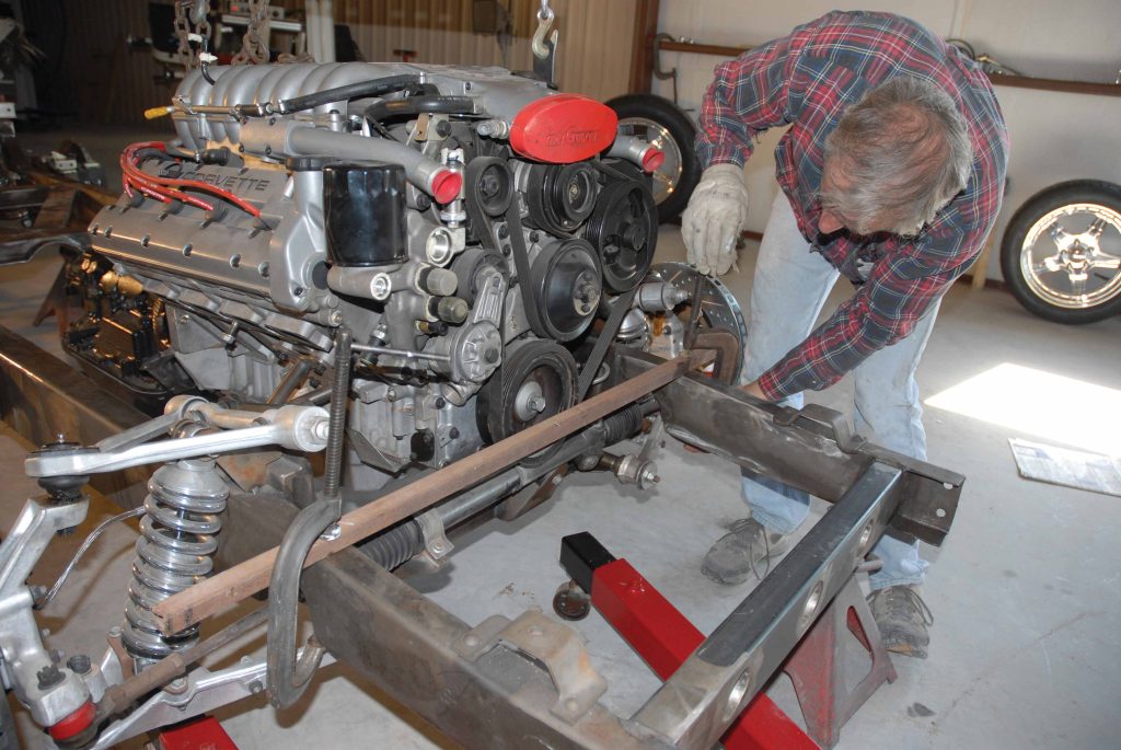
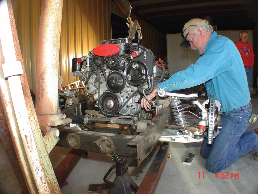
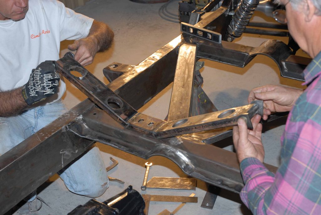
With that done, the time has come for the crew at Cimtex Rods in Jarrell, Texas, to actually install this potent ZR1/4L80E powertrain into the highly modified Flat Out Engineering/Corvette C4-equipped 1956 Chevrolet half-ton truck chassis. Of course, that required fabricating a new set of engine mounts, along with designing an adjustable transmission crossmember. Once the engine and transmission were securely in place, Tim and Darrell Cimbanin were able to have a custom aluminum driveshaft fabricated.  

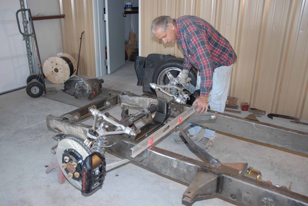
On paper it all sounded pretty good, but it would require a lot of time and thought, not to mention a generous supply of rectangular steel tubing, some flat stock and some round steel tubing.

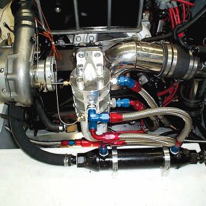
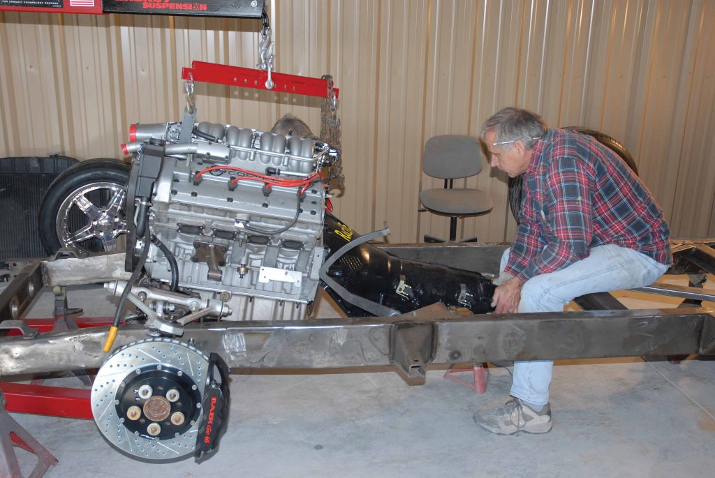
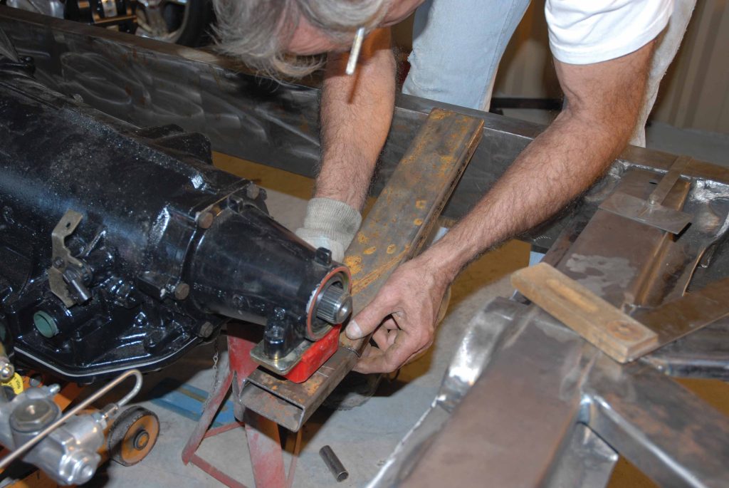
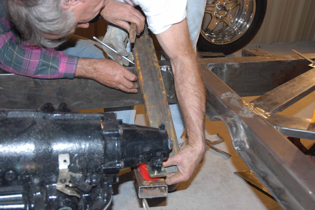
“After we bolted the Corvette ZR1 engine and Jimmy G. 4L80E electronic overdrive transmission together, we lowered it into the chassis,” said Darrell Cimbanin. “Early on, we had decided that we would be setting the engine back in the chassis a total of 6 inches, not only for better weight transfer but also to allow sufficient room to house the Be Cool four-core aluminum radiator and twin electric fans, the Turbonetics-Spearco intercoolers and the twin Powerdyne BD11-A silent-drive superchargers.”

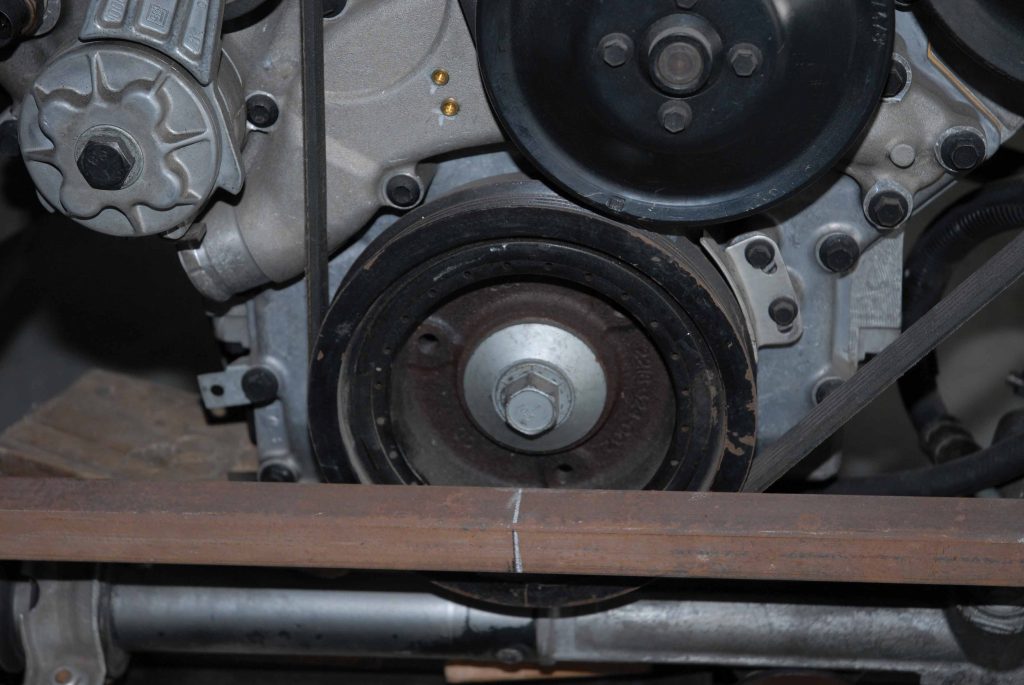
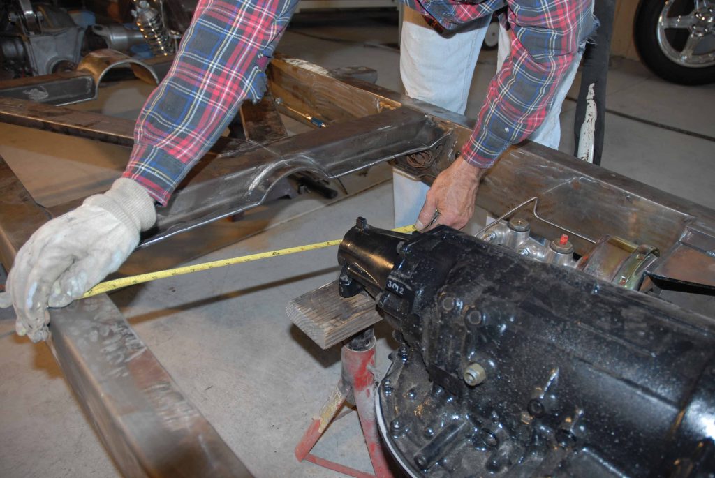
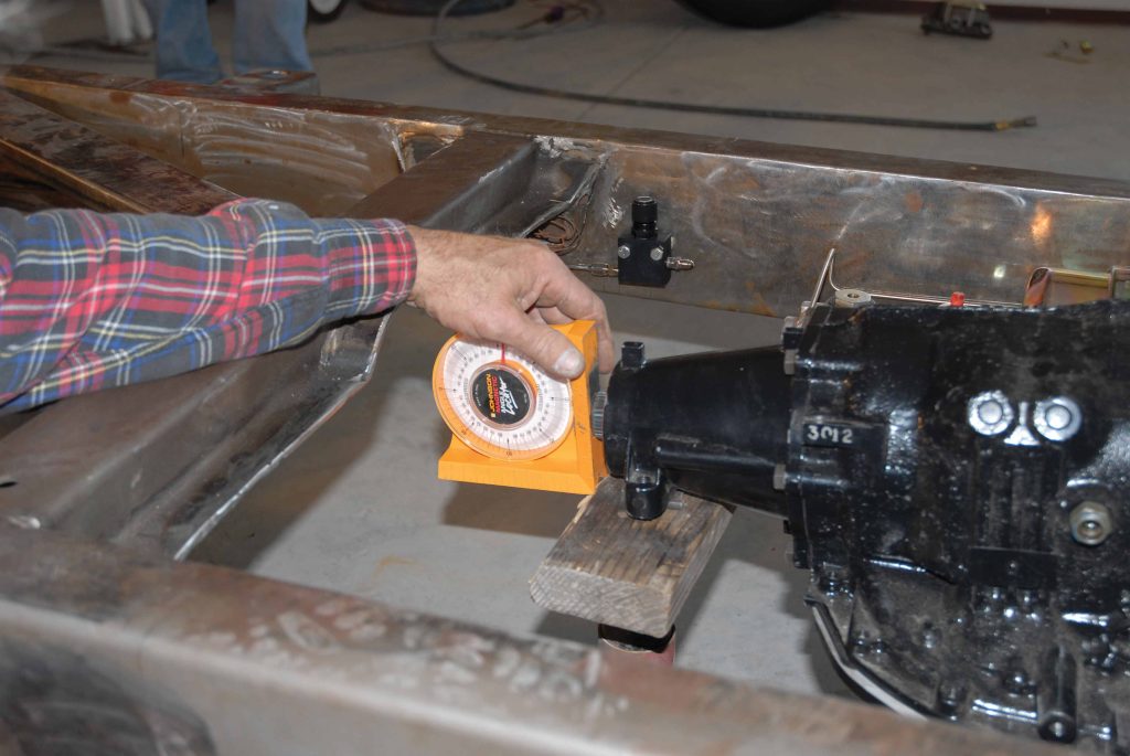
In order to accomplish this, the engine and transmission were first lowered into the chassis. Next the true centerline of the Corvette ZR1 engine was arrived at, using the crank bolt as a point of reference (15 inches center to center) and centering it between the front ?framerails. The centerline of the Jimmy G./GM 4L80E electronic overdrive transmission was likewise arrived at by measuring center to center off the tailshaft to the inside of the Super Cameo’s boxed-in framerails at 14-3/4 inches side to side.

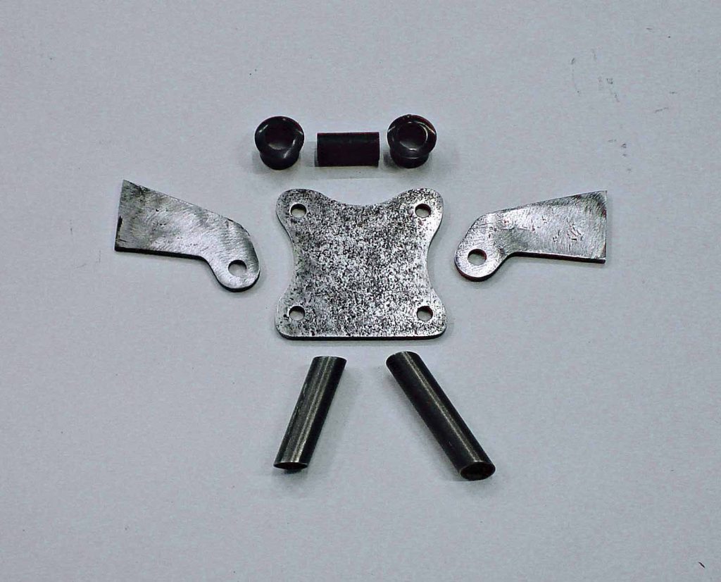
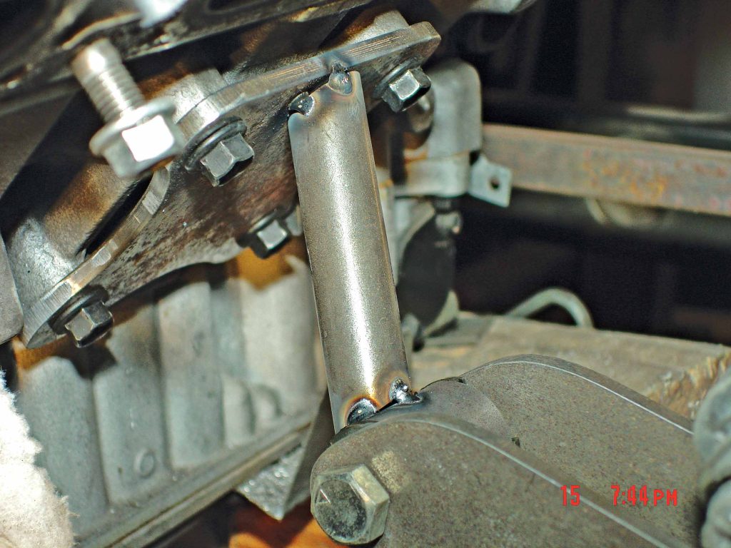
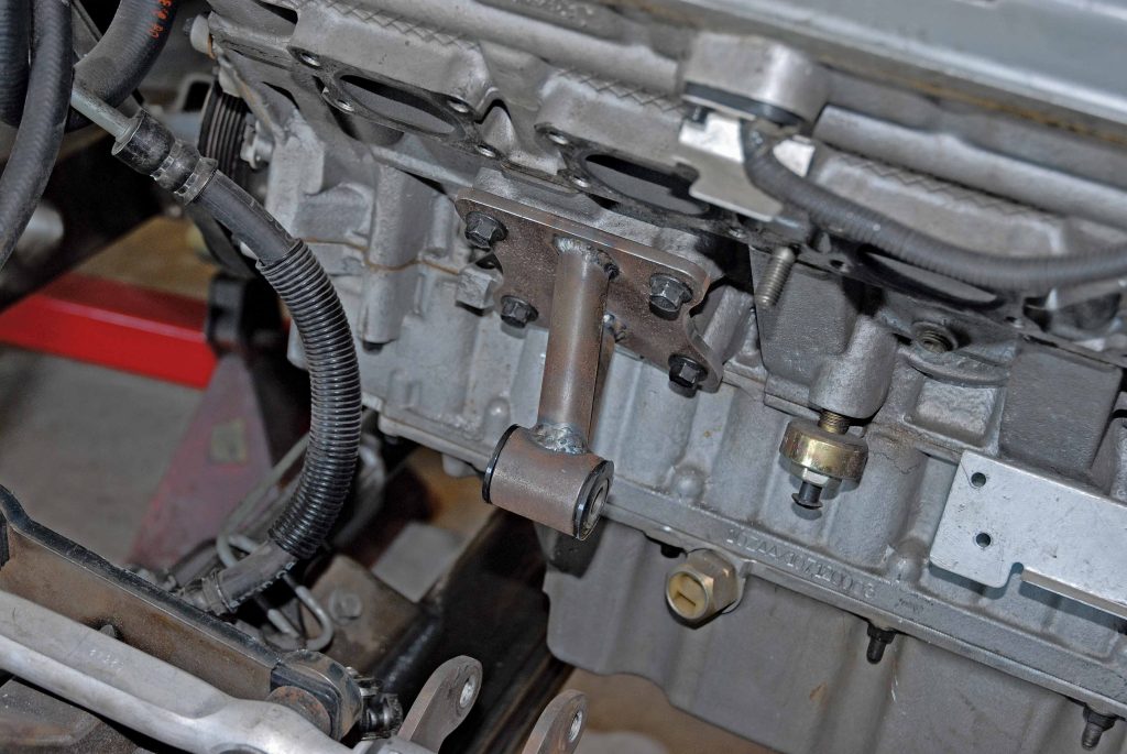
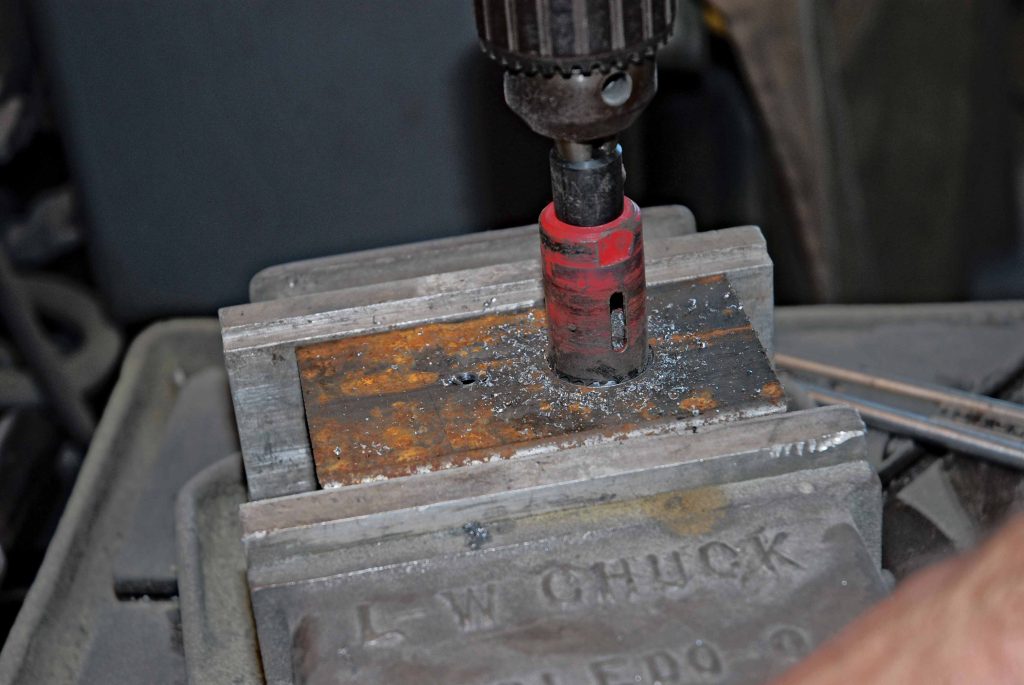
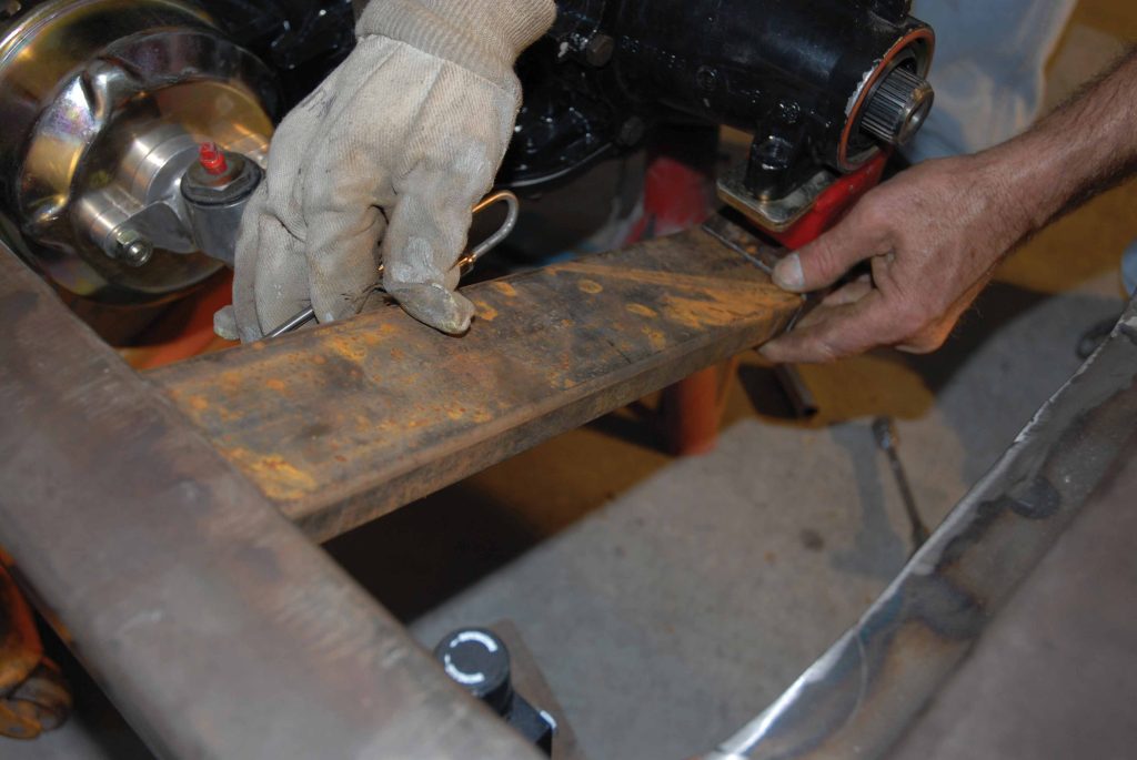
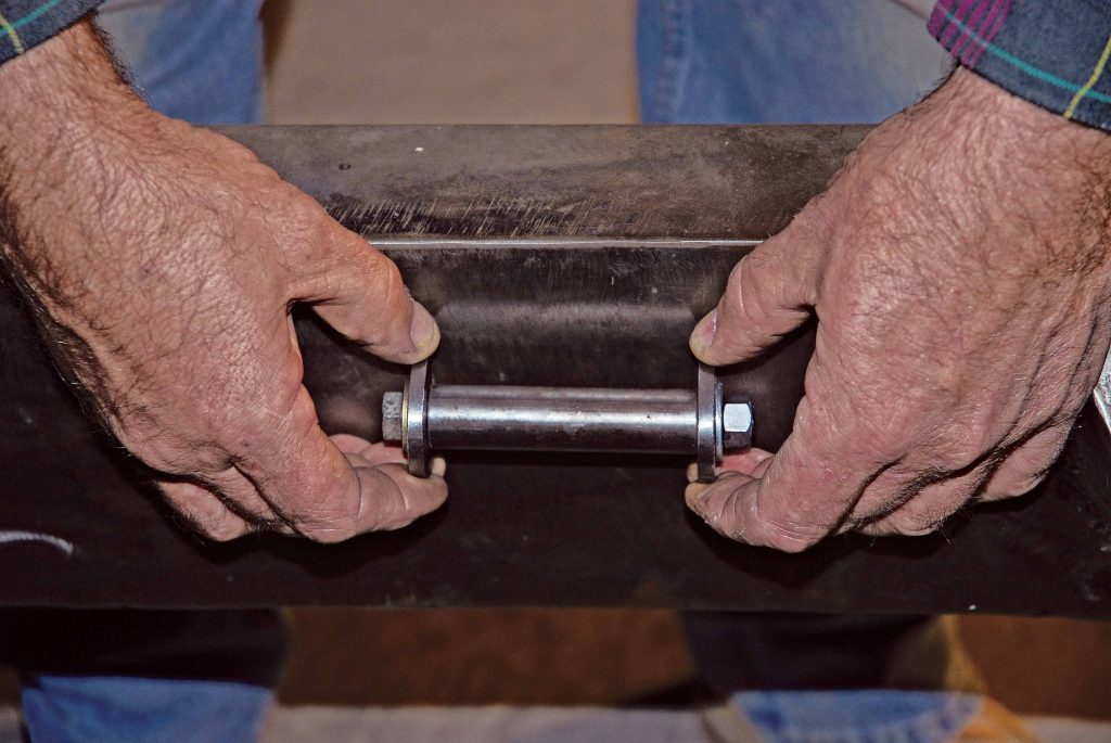
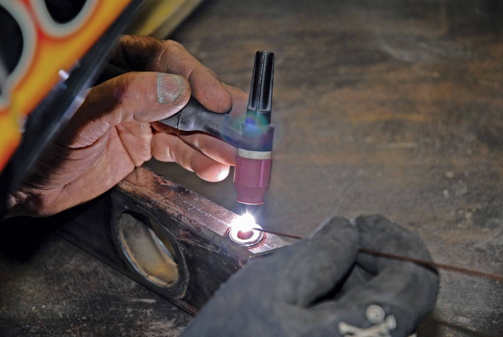
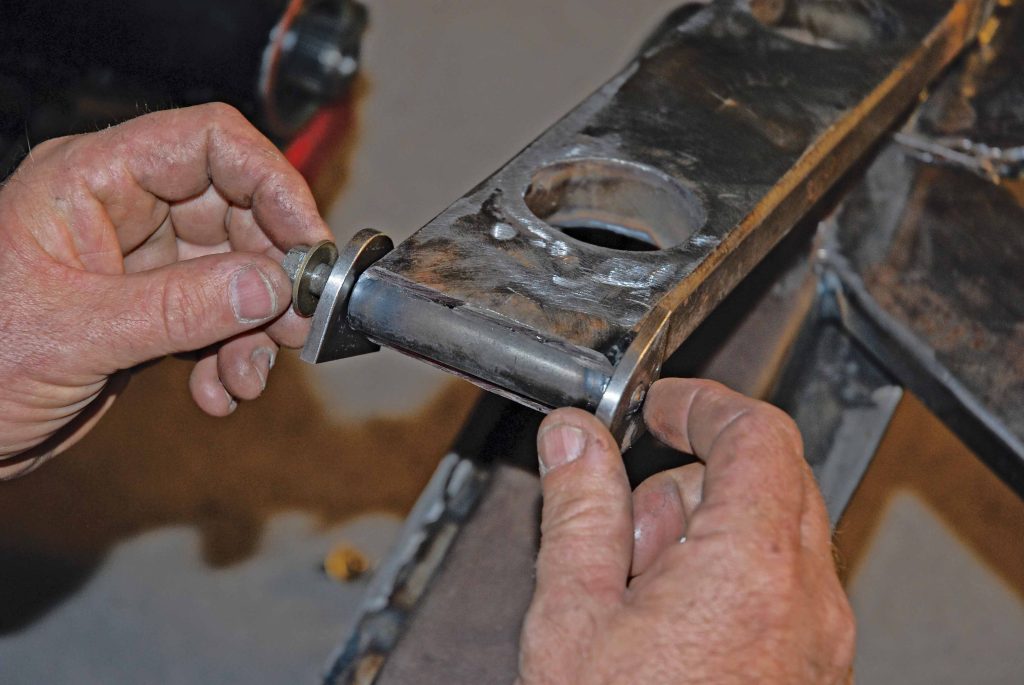
The actual motor mounts that secure this potent powerhouse in place consist of two pieces of rectangular 1/4-inch steel plates bolted to the engine using the OE Corvette ZR1 motor mount bolts. Welded to that are two 2-inch chromoly “fingers” in a “V” formation, welded to a piece of 1×1-inch round chromoly tubing with an Energy Suspension black graphite, polyurethane motor mount bushing pressed through it. These mounts bolt up to a pair of 1×2-1/2-inch mounting tabs welded to the inner rails of the chassis by a pair of 1/2×3-1/2×7/16-inch engine mounting bolts. It’s simple yet effective.

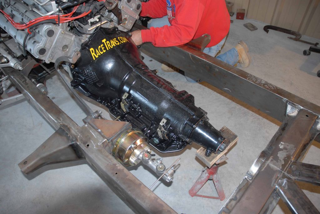
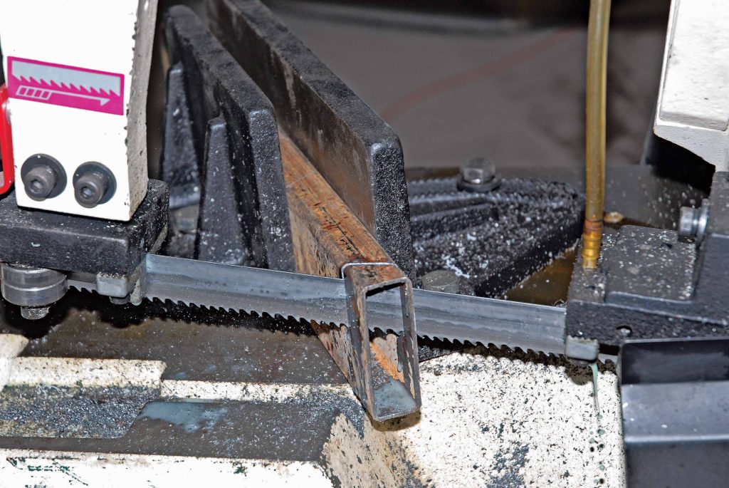
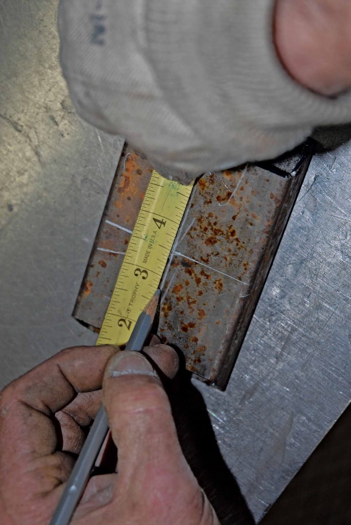
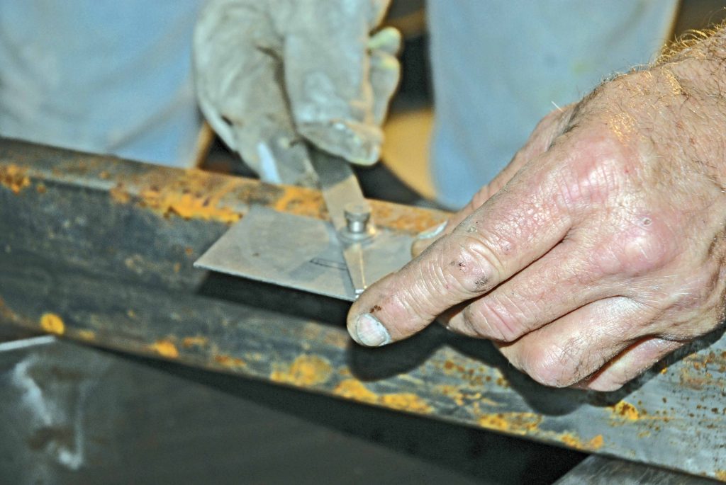
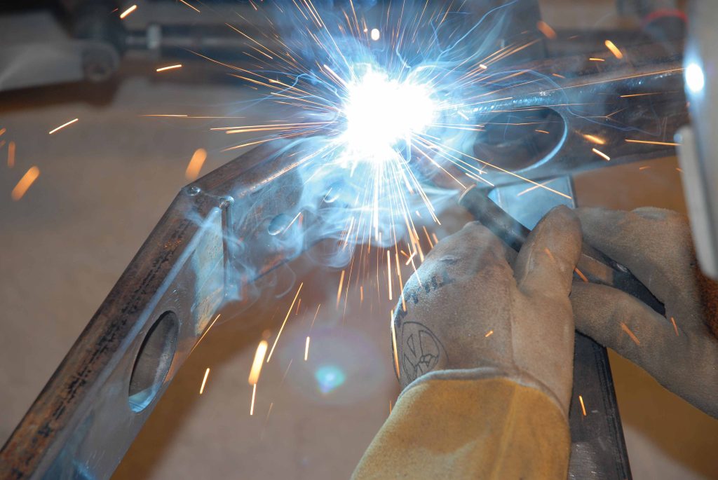
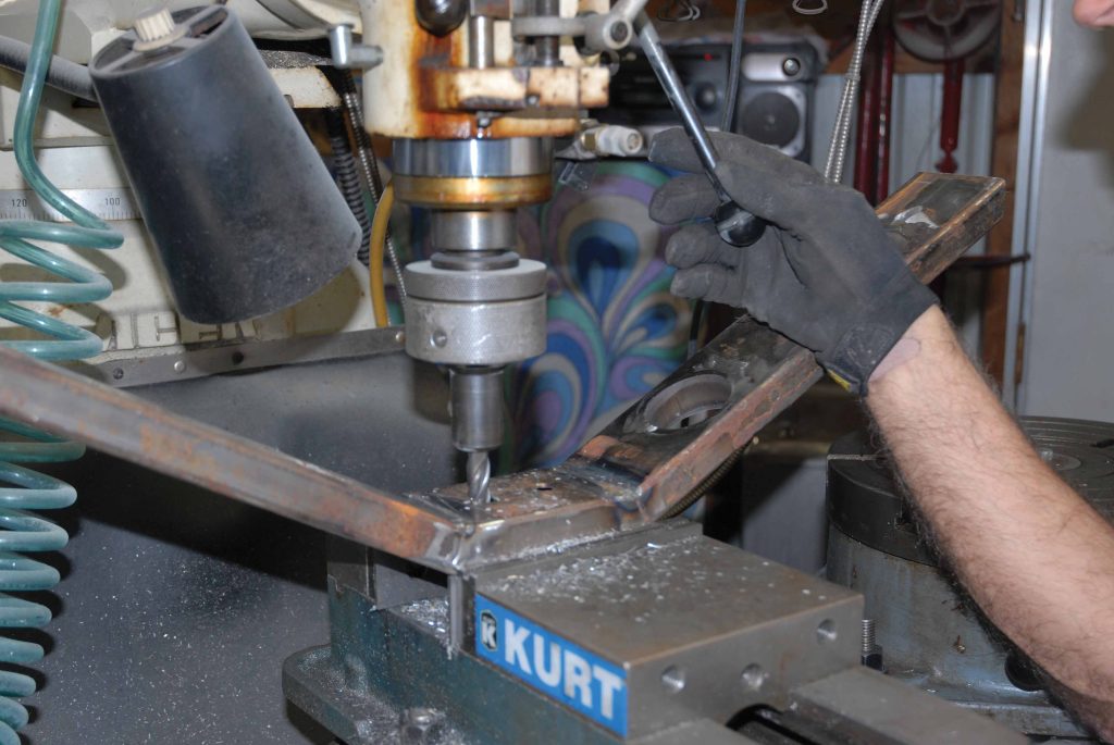
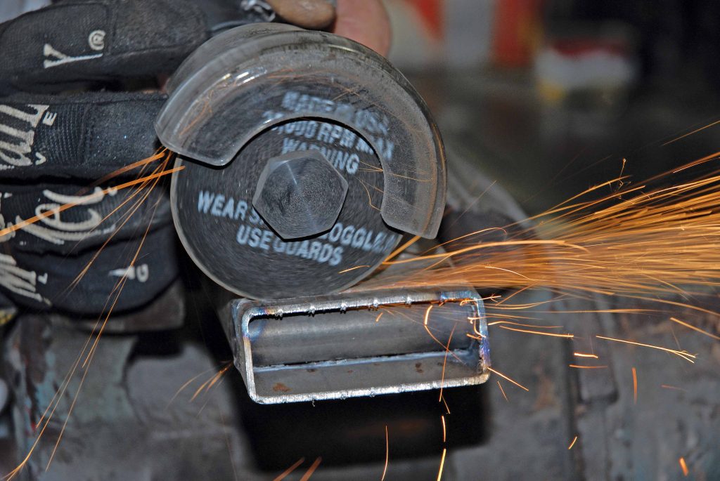
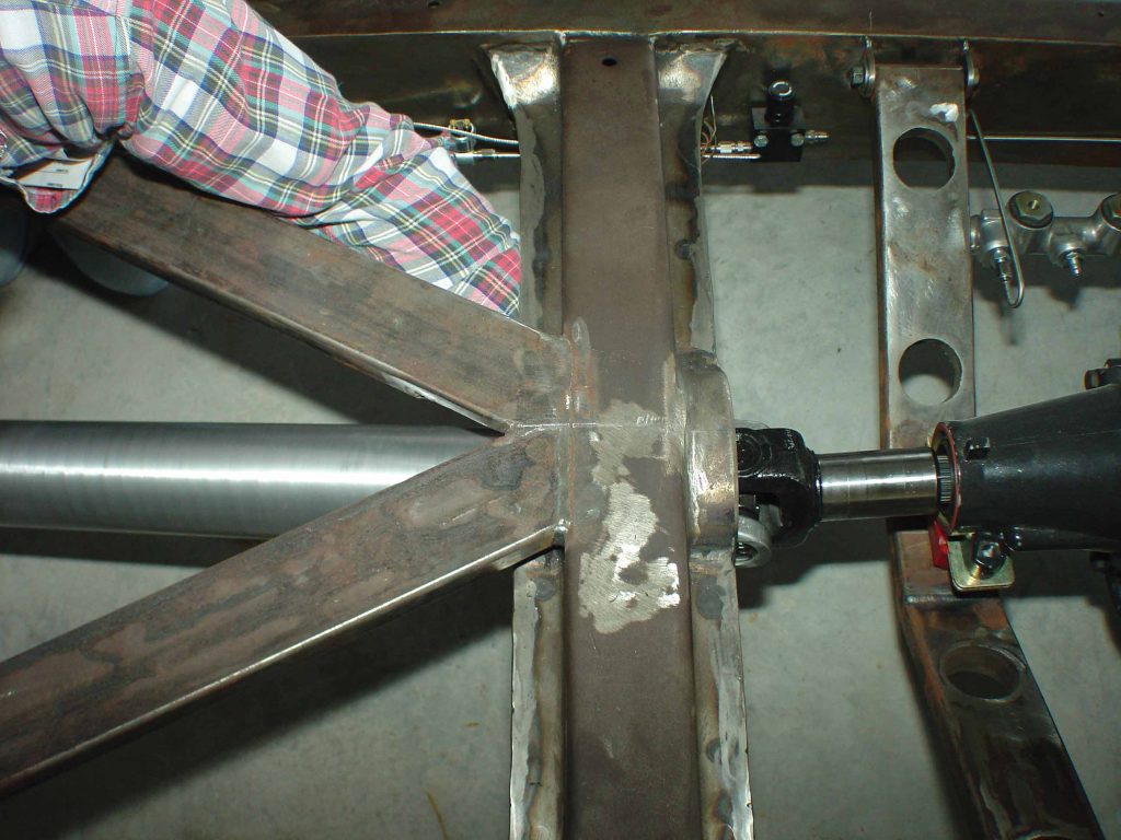
However, when it came to the transmission crossmember, things were a bit more complicated. From the get-go, several different transmission crossmember designs were discussed, including a trick sheetmetal design. But in the long run, something simple such as a 30-degree, U-shaped crossmember made out of a series of three pieces of 30-degree angle-cut, 1×3-inch rectangular box tubing measuring 13 inches on the side pieces and 5 inches on the center piece proved to be the most logical choice. 

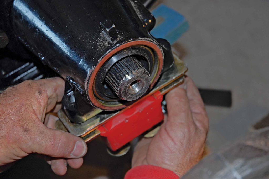
“The center of this mount (which uses an Energy Suspension-manufactured GM 4L80E isolator and polyurethane transmission mount, part No. 31108G) is slotted a total of 1-1/2 inches so that you can run a number of GM electronic overdrive transmissions, although we’re sticking with the GM 4L80E,” said Cimbanin. 

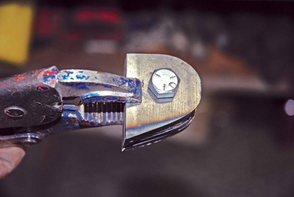
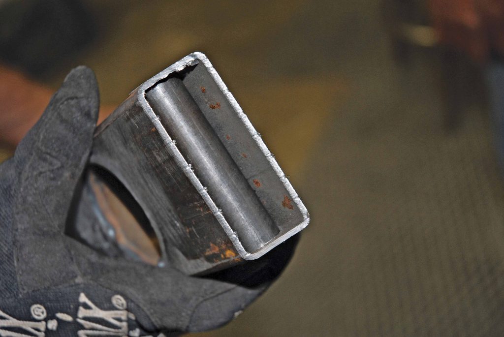
“We’ve also made this mount totally removable. Welded to each end of the crossmember is a piece of 3-inch steel tubing. The mount is bolted up to the chassis via a pair of 3/8x4x7/16-inch bolts secured to the chassis by a pair of custom-fabricated 1-1/2×2-inch mounting tabs. We’ve also placed a series of three         1-1/2-inch holes finished off with 1-1/2-inch-diameter round tubing welded in place. These holes not only improve the appearance of the transmission mount, but they also give it added strength!”

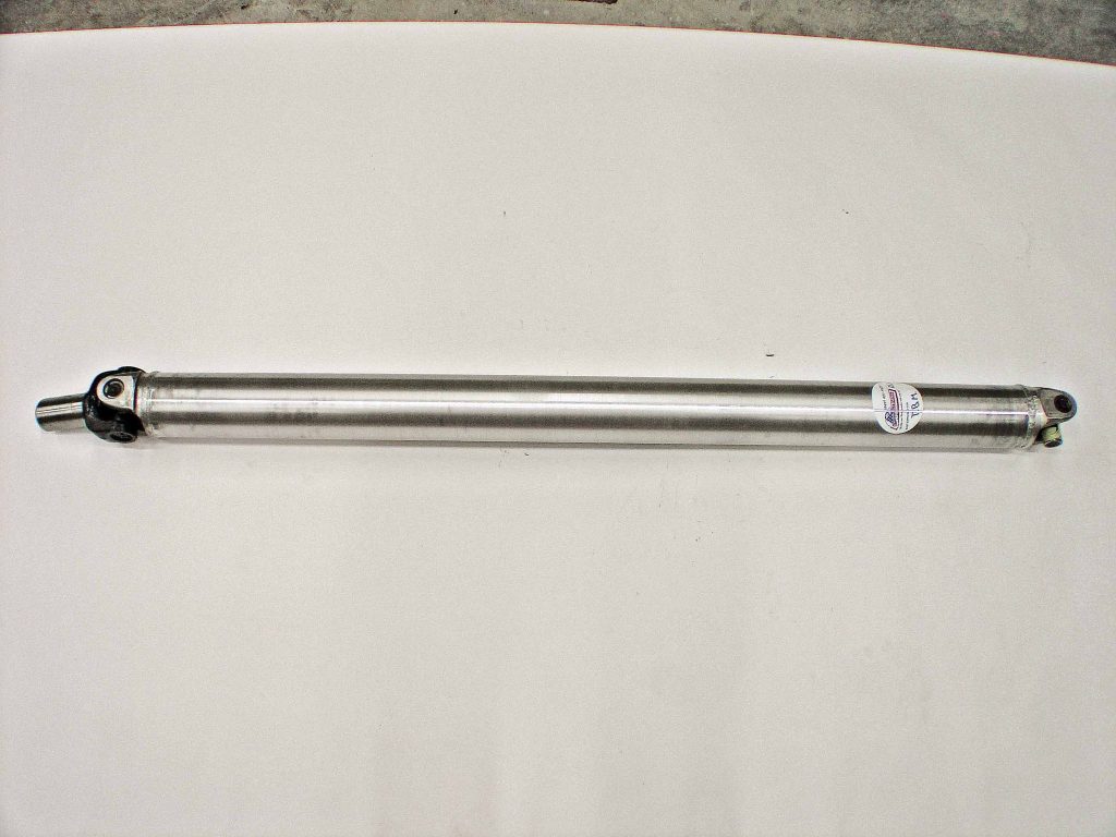
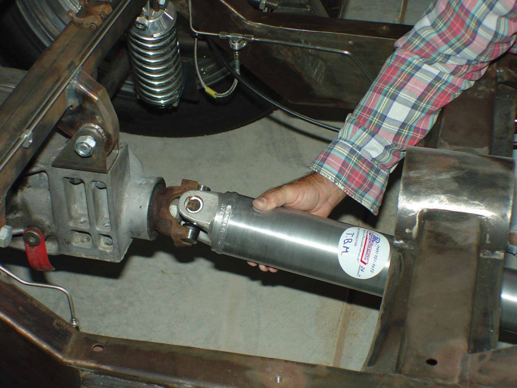
When it came to fabricating the fully balanced custom aluminum driveshaft, the Cimbanins contacted Wade King at Irvine, California’s Drivelines Inc. and ordered a unit measuring 51 inches in length that utilizes a GM 4L80E yoke on one end and an SAE-grade, 3/8-inch U-joint on the other. Since this driveshaft is manufactured out of aluminum, it’s not only lightweight but can also be show polished! 

Now follow along with us as Cimtex Rods’ Tim and Darrell Cimbanin and fabricator Creighton “The Real Deal” Deal show us how it’s done!

In Part VII we will be covering the fuel tank and the fuel system, the supercharger and the intercooler installation. Stay tuned. TB

The engine and transmission mockup begins with the bolting up of the Super Cameo’s Jimmy G./RaceTrans.com GM 4L80E electronic overdrive transmission to the special Mercury Marine-fabricated six-bolt flexplate.
Prior to actually dropping the engine and transmission in place, Darrell Cimbanin checks the Cameo chassis to make sure that it’s 100-percent level.
Project Super Cameo’s Corvette ZR1 engine and GM 4L8E transmission combination are then carefully lowered in place using a hoist, a floor jack and some 2x4s for leveling
A jackstand and a 2x4 temporarily serve as support for the tailshaft of our 4L80E.
With an engine set back in the chassis a total of 6 inches, it ultimately places the front crank pulley directly over the Corvette C4 steering rack once the engine is lowered in place. Note the piece of square bar stock C-clamped to the chassis. It will be used as a measuring bar.
Cimbanin uses the ZR1 crank bolt to center the engine in the chassis. A measurement of 15 inches is arrived at center to center and side to side.
Out back Cimbanin centers the tailshaft of the 4L80E, arriving at a measurement of 14-3/4 inches center to center and side to side.
An angle finder is also used to set the pinion angle of the tailshaft at 1-degree positive.
Cimtex Rods fabricator Creighton “The Real Deal” Deal begins fabricating the new motor mounts.
Ultimately Deal comes up with a plate-and-finger-design motor mount, which will use an Energy Suspension graphite-impregnated motor mount bushing.
The design is simple yet effective. Note that the top finger has already been tack welded into place.
A set of arms or mounting brackets was also fabricated and welded to the chassis in order to accept the actual mount itself. Two 1x3-1/2x7/16-inch mounting bolts are used.
Here’s the finished product!
Now it’s on to the rear crossmember. First Team Cimbanin installs the Energy Suspension GM 4L80E polyurethane transmission mount and insulator plate (part No. 31108G) using a series of four 3/8x4-inch SAE-grade bolts.
Next comes the fabrication of the actual rear crossmember. First a piece of 1x3-inch rectangular tubing is cut, measuring 5 inches for the center mount, or “pad,” of the transmission crossmember.
Next Cimbanin arrives at the true centerline of the tubing. Then he makes his initial measurements to drill his pilot holes.
After drilling a pair of 1/4-inch pilot holes, a 1-inch hole saw or auger bit is used to make series-two bolt holes in the transmission mounting pad.
Now it’s time to trial fit the pad onto the Energy Suspension polyurethane transmission mount using the supplied 3/8-inch bolts.
With the new transmission mounting pad securely bolted in place, Cimbanin begins making his measurements for the outer pieces, or “arms.”
After arriving at the correct measurement of 13 inches side to side, Darrell draws a 30-degree scribe mark and will make his cuts.
Now it’s time to trial fit the pad onto the Energy Suspension polyurethane transmission mount using the supplied 3/8-inch bolts.
Now it’s time to fabricate the left-side arm of the GM 4L80E transmission mount.
The next order of business is the drilling of a series of three 1-1/2-inch holes in the support arms. This is done both for looks and strength. Once the holes have been drilled, pieces of 1-1/2-inch tubing are finish welded in, and then everything is ground smooth.
The next step is the fabrication of the mounting sleeves, which will be pressed and welded into the ends of the support arms. These sleeves are made out of 3/4x3-inch mild steel tubing and are opened up to an inner diameter of 3/8 inch.
While all of this is going on, Tim Cimbanin fashions two sets of mounting tabs or eyelets out of 3/8x1-1/2x1-1/2-inch flat stock and drills a 3/8-inch hole dead center. These tabs will ultimately be welded to the inner rails of our ’56 Cameo’s chassis.
The next order of business is the drilling of a series of three 1-1/2-inch holes in the support arms. This is done both for looks and strength. Once the holes have been drilled, pieces of 1-1/2-inch tubing are finish welded in, and then everything is ground smooth.
Next our installers bolt the new crossmember mounting tabs together to arrive at the proper mounting location on the chassis.
Over on the drill press, Darrell cuts the adjuster slots into the face of the new transmission crossmember mounting pad.
Then comes the drilling of a pair of 3/4-inch holes at the corresponding ends of the new transmission crossmember “arms.”
At this juncture, these pieces are pressed into the openings and final welded in place.
All that remains is trimming off the excess material on the ends of the arms and grinding the ends smooth.
Next the mounting tabs are bolted up to the arms of the newly fabricated transmission crossmember.
This completed assembly is dropped into place and bolted up to the GM 4L80E crossmember mounting pad.
Just a little finish welding on the tabs and it’s a done deal!
While the guys at Cimtex Rods were busy constructing the engine and the transmission mounts on the Super Cameo, Wade King of Drivelines Inc. was busy fabricating a fully balanced aluminum driveshaft. Measuring a total of 51 inches end to end, this unit uses a GM 4L80E yoke on one end and a 3/8-inch U-joint on the other.
Darrell Cimbanin trial fits the new shaft to the Corvette C4 rear carrier. Everything fits just fine.
The same thing goes for the transmission yoke. This is a real quality piece!

ARTICLE SOURCES

Picture of Cimtex Rods

Cimtex Rods

P.O. Box 205
Jarrell, TX 76537

512/746-2707

Picture of Drivelines Inc.

Drivelines Inc.

#6 McLaren St., Ste. M
Irvine, CA 92618-2817

800/963-7483

Picture of Energy Suspension

Energy Suspension

1131 Via Callejon
San Clemente, CA 92673

949/361-3935

Download Nulled WordPress Themes
Download Premium WordPress Themes Free
Premium WordPress Themes Download
Download WordPress Themes
udemy free download
download karbonn firmware
Download Premium WordPress Themes Free
ZG93bmxvYWQgbHluZGEgY291cnNlIGZyZWU=
Scroll to Top