

Edit Template
THE AUTO BUILDER
Menu
Featured

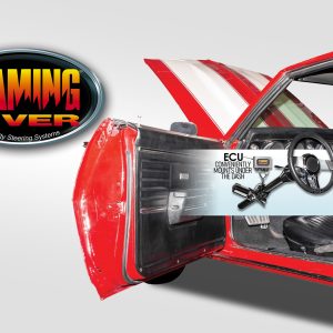
PRODUCT SPOTLIGHT: Flaming River’s Microsteer Tilt Column for 1967-68 Camaro
Imagine yourself behind the wheel of your vintage Camaro, cruising the streets with the perfect blend of classic aesthetics and modern performance. That dream becomes a reality with the Microsteer Tilt Column. But what sets this beauty apart? Let’s talk about the Microsteer Power Assist feature, a game-changer that takes your driving to new heights.

SUBTLE AND SMOOTH
The path old hot rods travel is often an amazing one; some hot rods saw a world of change in their many years of service, while others remained hidden from the saws and torches, thus saving them from mutilation and lackluster workmanship. The ’34 Ford on these pages is one such example of a car that maintained its integrity through nearly three quarters of a century. Finding this jewel was a dream come true for John Cox, when he bought the coupe as a driver and realized it had lived an easier life than most, even though its original chassis had been modified.
THE OLD AND THE NEW
The relentless progress of technology is a difficult topic for those of us captivated by the cars and lifestyles of a bygone era. As technology advances at an exponential rate, we now find ourselves clamoring to keep up with the latest and greatest products that simultaneously render many of our old favorites obsolete. Just about the time you figure out how to use your new digital camera and multifunction cell phone, you find out that someone decided it was necessary to combine the two. The struggle to balance the conveniences of modern technology with our nostalgia is especially difficult for many street rodders.


Spotlighter
POPULAR READS
-
Product Spotlight: Bill Mitchell Products Aluminum LS Engine Block
-
PRODUCT SPOTLIGHT: 60-66 Chevy C10 Fresh Air Vent Block Off Plate
-
Product Spotlight: Pyramid Optimized Design Sequential Aurora Taillight for 1964½–1966 Mustang
-
PRODUCT SPOTLIGHT: Cam Covers for GEN/3 Coyote from Pyramid Optimized Design
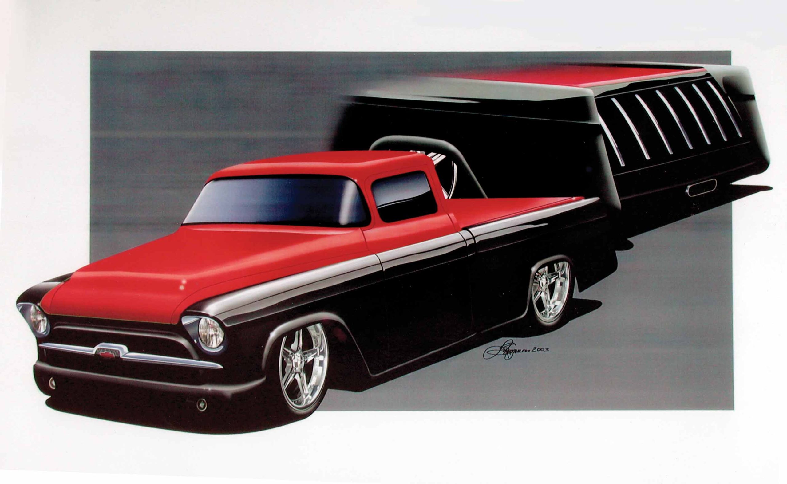
CIMTEX RODS SUPER CAMEO: PART 3
It’s Time to Bring Up the Rear With the Installation of a Modified 1986 Corvette IRS
Cimtex Super Cameo Buildup: Part III – Rear Frame Rail Modifications
In Part III of our Cimtex Super Cameo buildup, we’re going to follow along as the guys from the Jarrell, Texas, crew modify the rear framerails on this ’56, “kicking it up” a full 8 inches. In the process, Tim and Darrell will also narrow the Corvette C4 IRS half shafts to achieve the much desired rear tire clearance they need in order to be able to run a set of humongous 20×10 billet wheels wrapped with a set of BFGoodrich radial T/A rubber.
Measuring and Cutting the Frame Rails
First the Cimbanins made certain that in the process of all their hammering and welding on the front of the ’56’s chassis, the rear framerails did not warp or shift their position. Once satisfied that things were in order and the framerails were as intended, the brothers constructed a pair of 45-degree, 2×3-inch box tube kickups measuring 8 inches tall. Next the ’56’s wheelbase was measured from the centerline of the Corvette C4 front spindle to the rear of the chassis, and a reference mark was scribed on the stock rear kickup at exactly 114 inches. With the truck’s wheelbase set in stone, our installers were also able to arrive at the correct centerline for the new rear kickups. “When we made our measurements, we also set the kickups at three degrees positive angle, which maintains the built-in rake of the chassis,” said Darell.
Once those measurements were made, the crew used a Craftsman plasma cutter to remove the stock rear centersection of the ’56 chassis, leaving only a small portion of the rear frame section temporarily intact for future reference. Then they tack welded the new kickups to the main rails, and once again they checked and rechecked their measurements prior to final welding these new pieces in place. Then they discarded the remaining portion of the back rails and fashioned new ones made out of 2×3-inch mild steel box tubing. “That pretty much takes care of the back half of the chassis,” commented Darrell. “Our next step was setting up the Corvette rear suspension!”
Installing the Corvette Rear Suspension
After removing the stock Corvette truss work, the Cimbanins placed the aluminum inspection cover from the Corvette C4 gear carrier in a mill and milled off the mounting bosses. From there, the guys trial fit and centered the Flat Out Engineering Corvette C4 rear crossmember, setting it at a neutral pinion angle. Then it was tack welded into place. Note that there is a welded-on bracket on this crossmember that centers and supports the C4/C5 gear carrier.
Once the Cimbanins had achieved the correct suspension geometry using the stock C4 Corvette trailing arms, they custom fabricated a set of adjustable upper and lower control arms to replace the bulky OE units. These arms are manufactured from 4130 chromoly and measure 11 inches top and 13 inches bottom in length. Once completed, these new arms were outfitted with Energy Suspension polyurethane suspension bushings and bolted to the Flat Out Engineering control arm mounting brackets and hub carrier. At this juncture, Darrell scribed a cut line at the top of the C4 hub carrier where the mounting tabs originally held the truss work in place, and they, too, will be milled off.
Fabricating Adjustable Torque Arms and Coilover Shocks
Next our installers began fabricating a set of four adjustable 4130 chromoly rear torque arms, which will replace the former truss work. These units measure 18 inches in length and feature Energy Suspension polyurethane suspension bushings. Along with the torque arms, the Cimbanins also fabricated a set of 3/8-inch cloverleaf mounting plates, using 1-3/4×1-7/8-inch aluminum spacers that bolt directly to the Corvette gear carrier. “Everything was made adjustable to within 1/2 to 1 inch in either direction, positive or negative camber,” said Darrell. “That way we can set camber and toe-in on the rear suspension without any problems.”
Cimtex Super Cameo Buildup: Part III – Completing the Rear Frame Rails
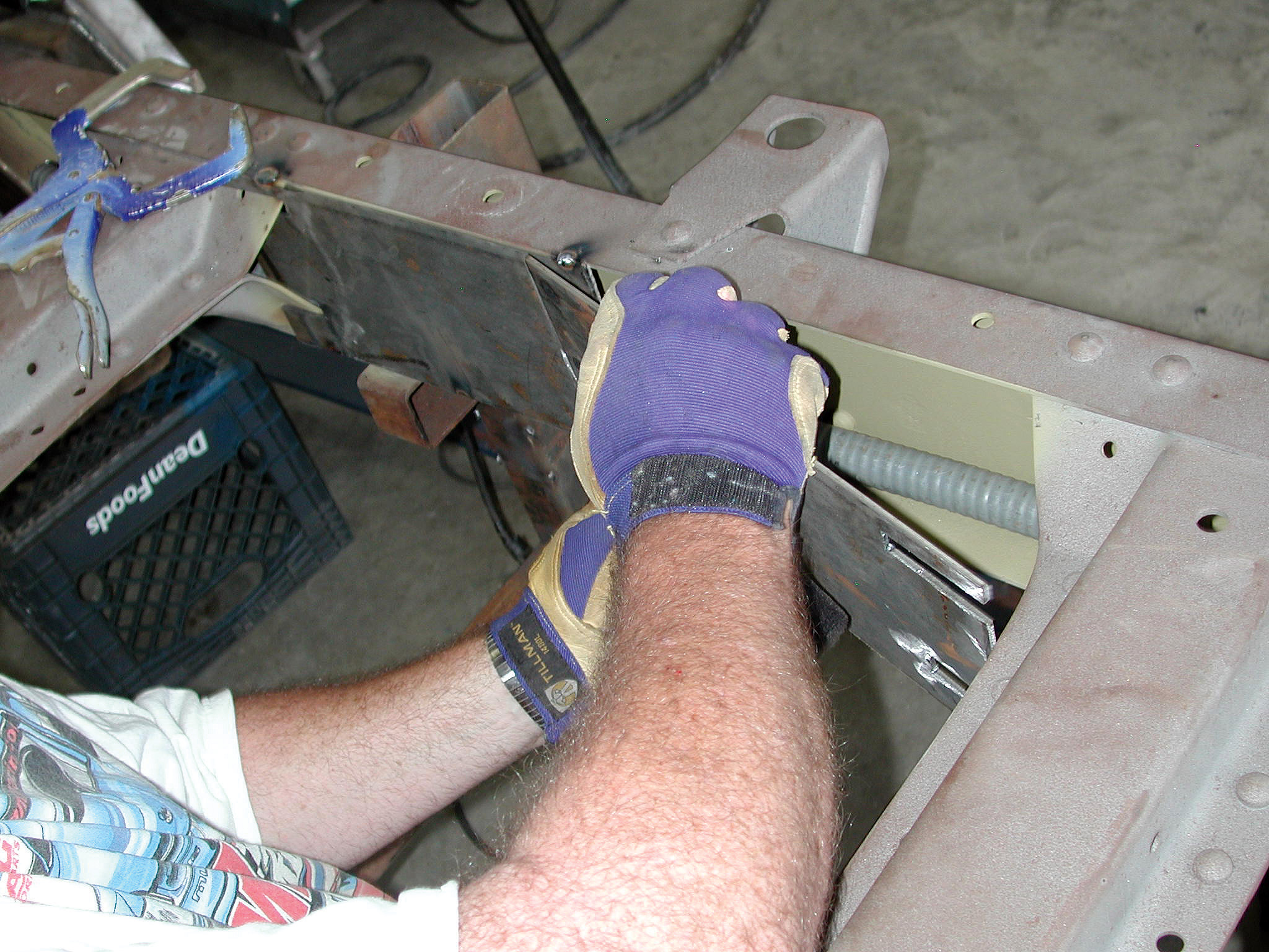
Finally the guys at Cimtex installed a pair of Aldan Eagle No. 659 coilover shocks using a pair of 12-1/2-inch-long, 400 lbs-in coil springs offset at 25 degrees. Of course, when the final suspension is up and running, this setup will also include a pair of four-piston, Baer Racing Pro Touring disc brakes along with Chisenhall/Russell Performance stainless steel brake and fuel lines, which will be hidden inside the chassis. A length of 1-inch-diameter Romex electrical cable was run through both sides of the Cameo’s framerails prior to completely boxing the remainder of the chassis in 3/16-inch flat stock. That way, all brake and fuel lines will enter/exit through the driver’s side of the chassis, and all electrical lines will run through and exit on the passenger’s side.
Installing Driveshaft Loops
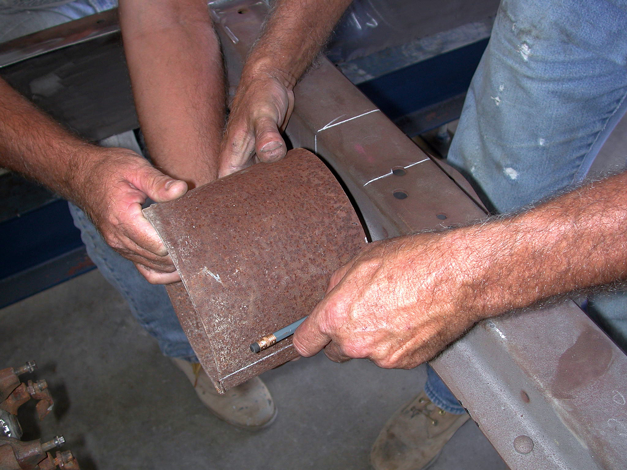
In the process, Team Cimtex also fashioned a pair of driveshaft loops out of a piece of 3x6x3/8-inch sectioned steel pipe. These loops are kicked up a total of 4 inches on the rear crossmember and 2 inches at the front crossmember. Of course, installation was as easy as locating dead center on both OE crossmembers and then measuring the outside diameter of the pipe. With that done, an angle cut was made to correspond to the circumference of the pipe. Then both pieces were welded in place.
Finishing Touches on the Chassis
At last the brothers Cimbanin welded up all the superfluous holes, as well as all the mounting brackets (both OE and custom) on Super Cameo’s chassis. Then everything will be bodyworked to perfection prior to being painted a bright red.
Up Next: Engine and Drivetrain Installation
In our next installment, we’re going to mount the ZR1 Corvette engine, as well as build the engine and transmission mounts, install the Jimmy G./racetrans.com-assembled GM 4L80E electronic overdrive transmission and hook up our custom-fabricated driveshaft. We’ll also install the Baer four-wheel disc brakes, the pedal assembly, the master cylinder and the power brake booster, as well as all of the brake and fuel lines, so stay tuned!
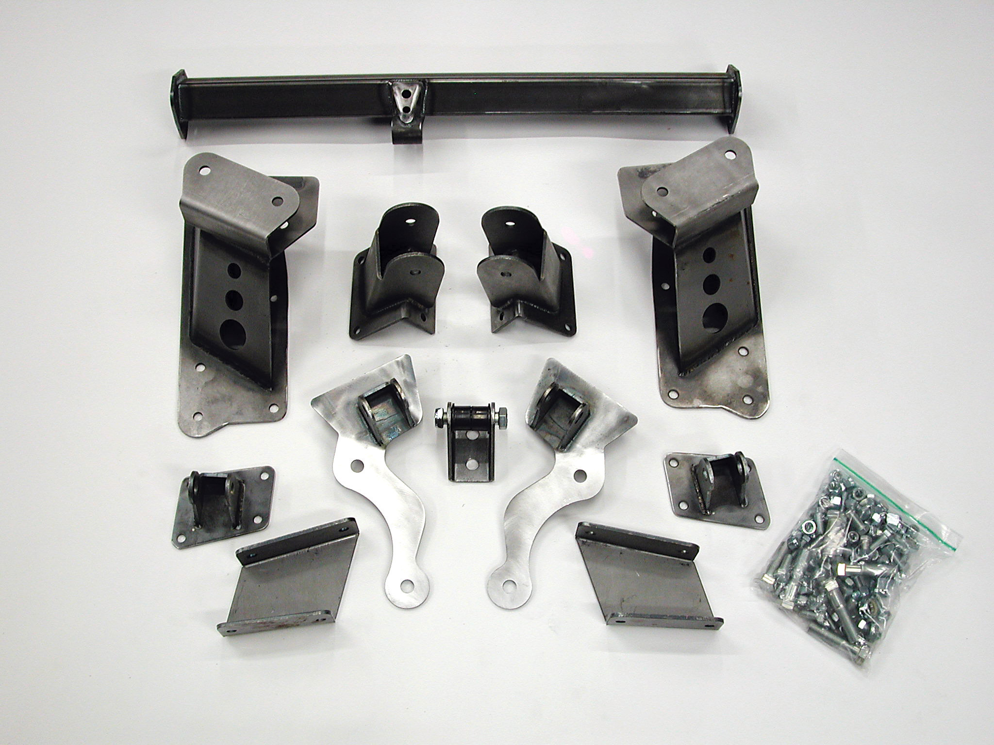
1. Shown is the Flat Out Engineering Corvette C4-based rear suspension kit for ’55-’59 Chevrolet and GMC 1/2- and 3/4-ton light-duty trucks. This kit allows the end user to choose either an ’84-’87 Corvette C4 or an ’88-’96 Corvette C6 independent rear suspension (IRS). Under normal circumstances, this would be a straight weld-in proposition. However, since the Cimbanins intended to perform a number of custom tweaks to the rear of the Cimtex Super Cameo, they were using only various components from the kit.
2. Measuring from the front spindle back, the Cimbanins arrived at a rear axle centerline of 114 inches. Once they made their marks, chassiswork could continue to the proper spec.
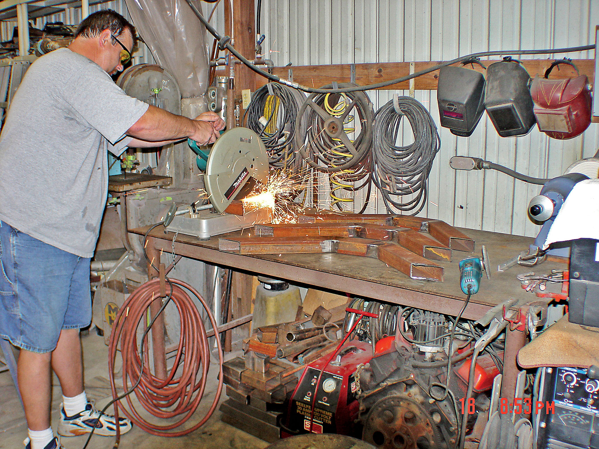
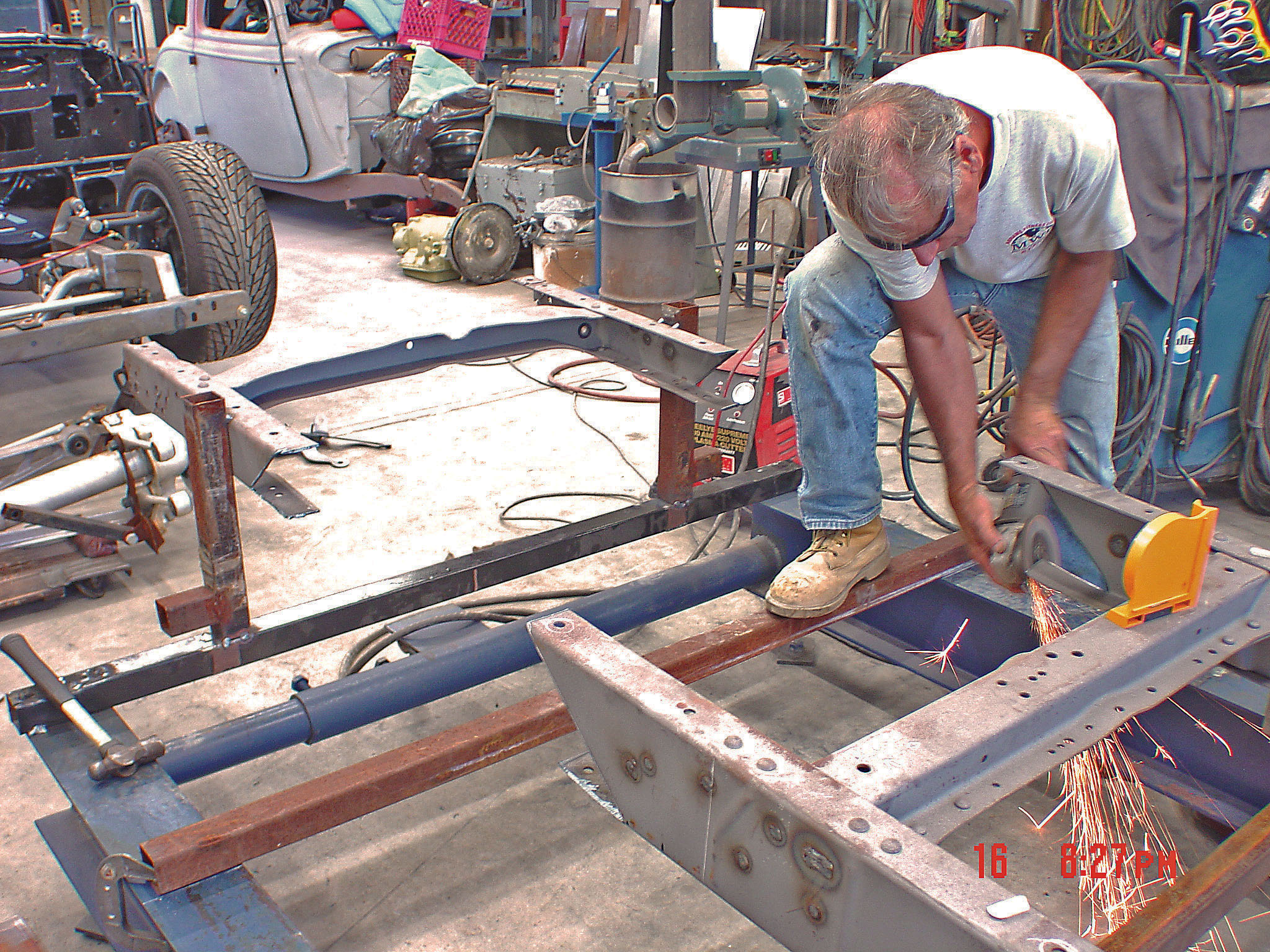
3. Cimtex fabricator Greg Keith is seen cutting the final pieces for the rear chassis kickups. These pieces were made out of 2x3-inch mild steel box tubing and are angled at 45 degrees on each end. Once installed, the overall kickup on the rear of the chassis will be a total of 8 inches.
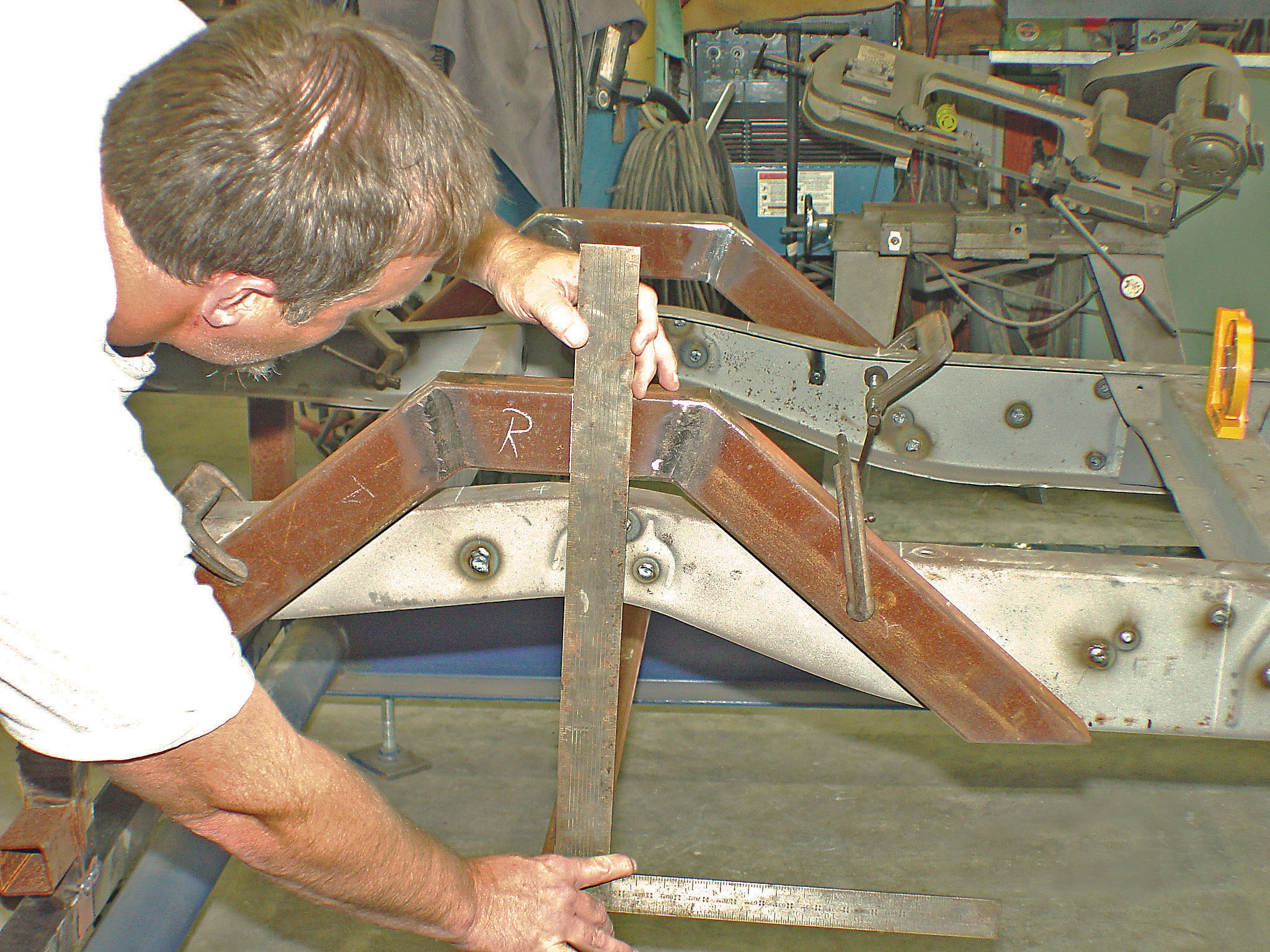
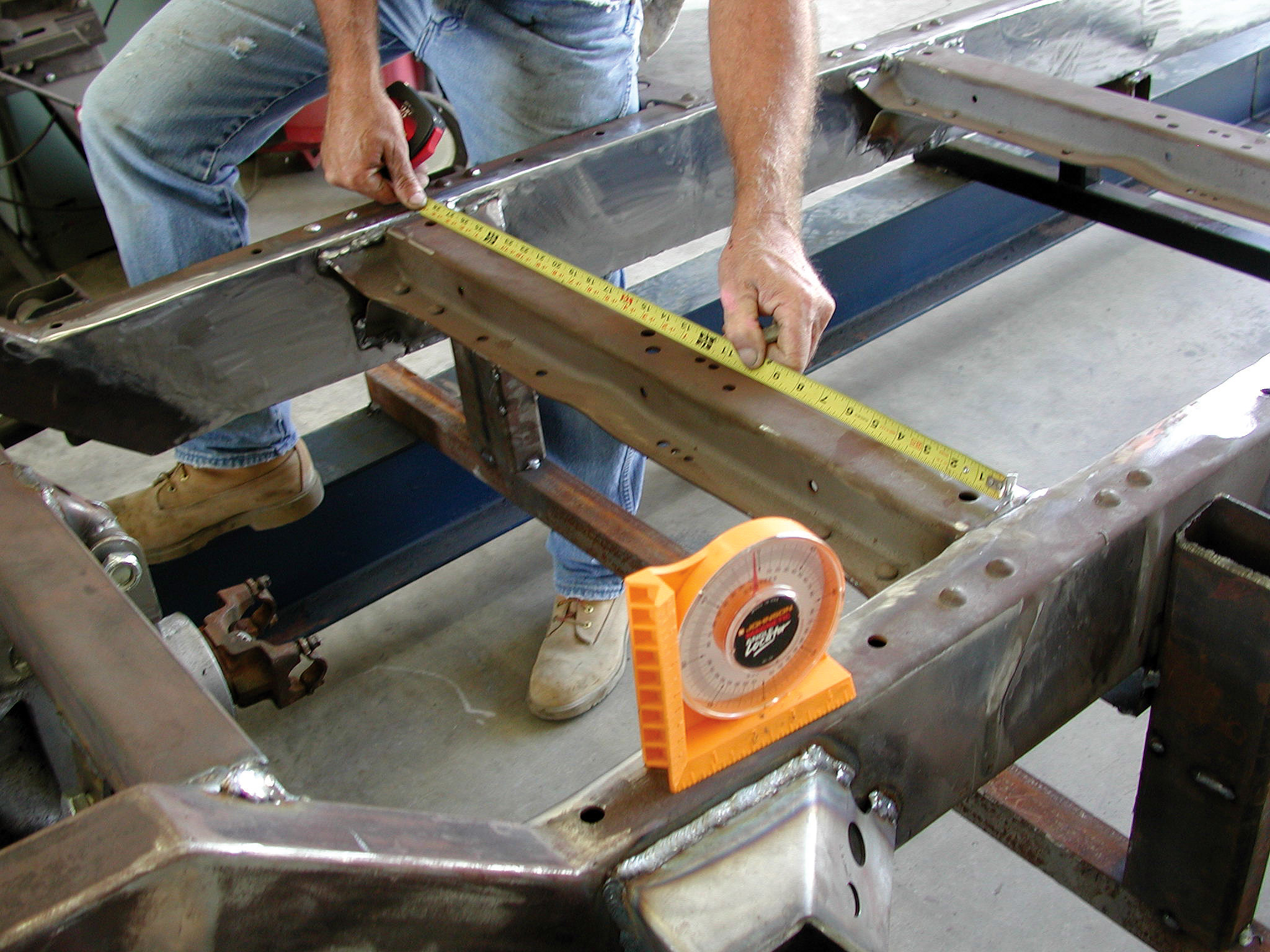
4. With the new kickups clamped into position, Keith checks the ride height. These kickups were also set at three degrees positive angle in order to maintain the rake built into the front of the tri-5’s chassis.
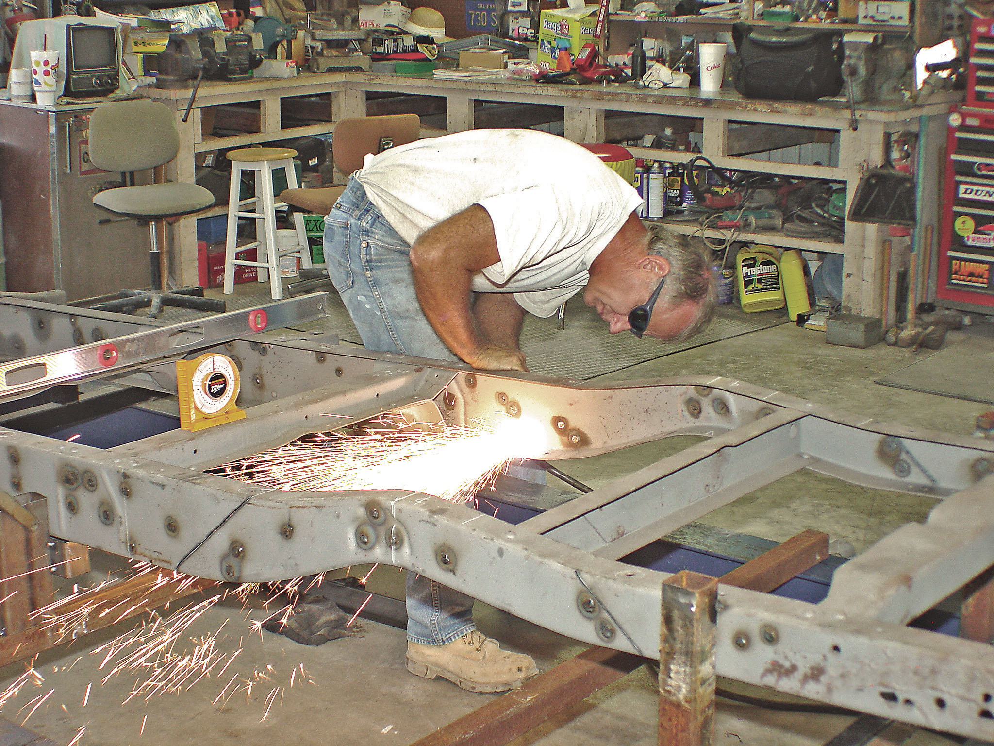
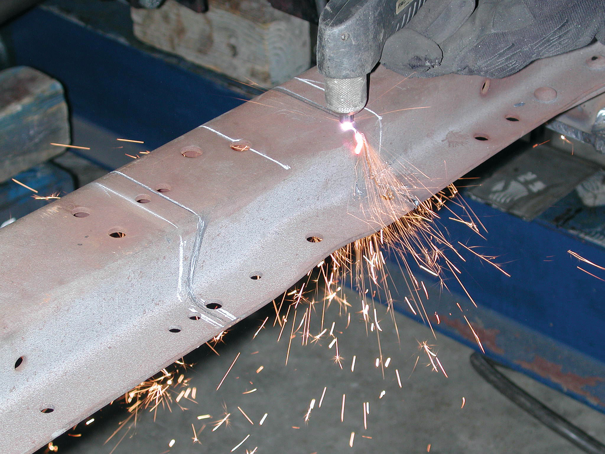
5. First Darrell uses his trusty Craftsman plasma cutter to trim the rear of the factory tri-5 kickup, leaving what’s left of the old back rails temporarily in place for reference.
6. Next Darrell trims the front rails with the plasma cutter in the same fashion.
7. With the factory tri-5 rear frame kickups and rear crossmember removed, Darrell grinds away all the dings.
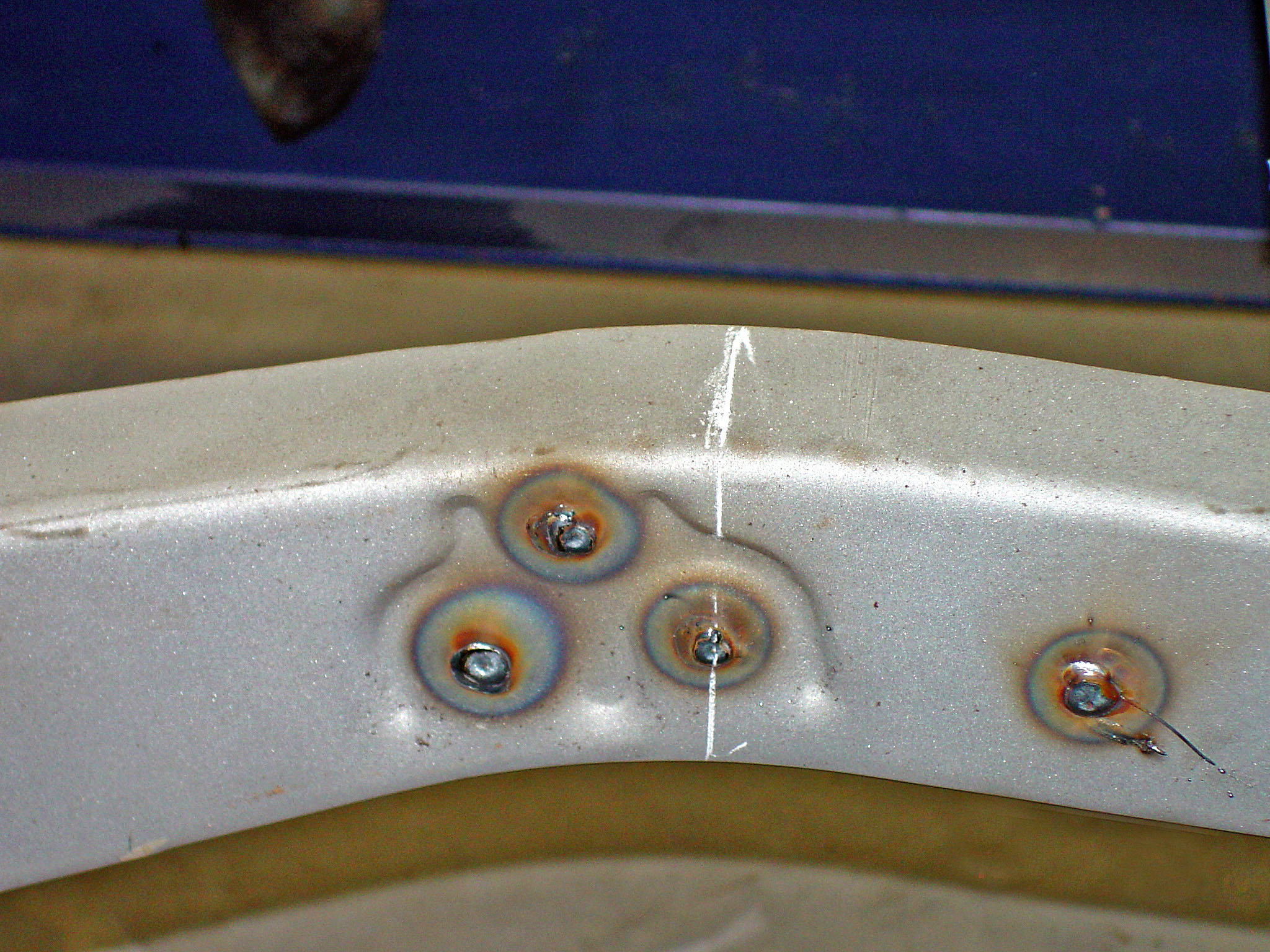
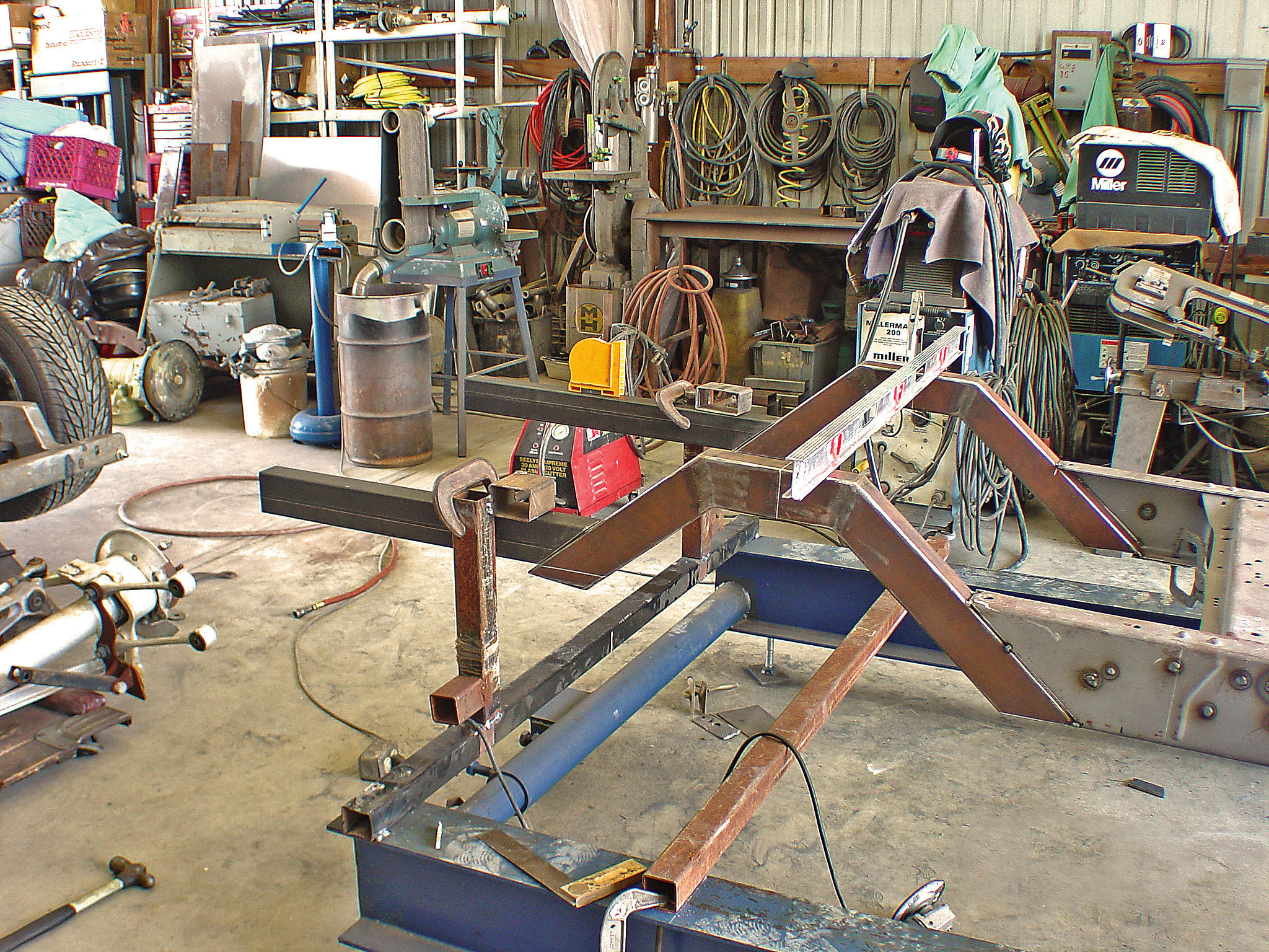
8. The new rear kickups and framerails are tack welded in place.
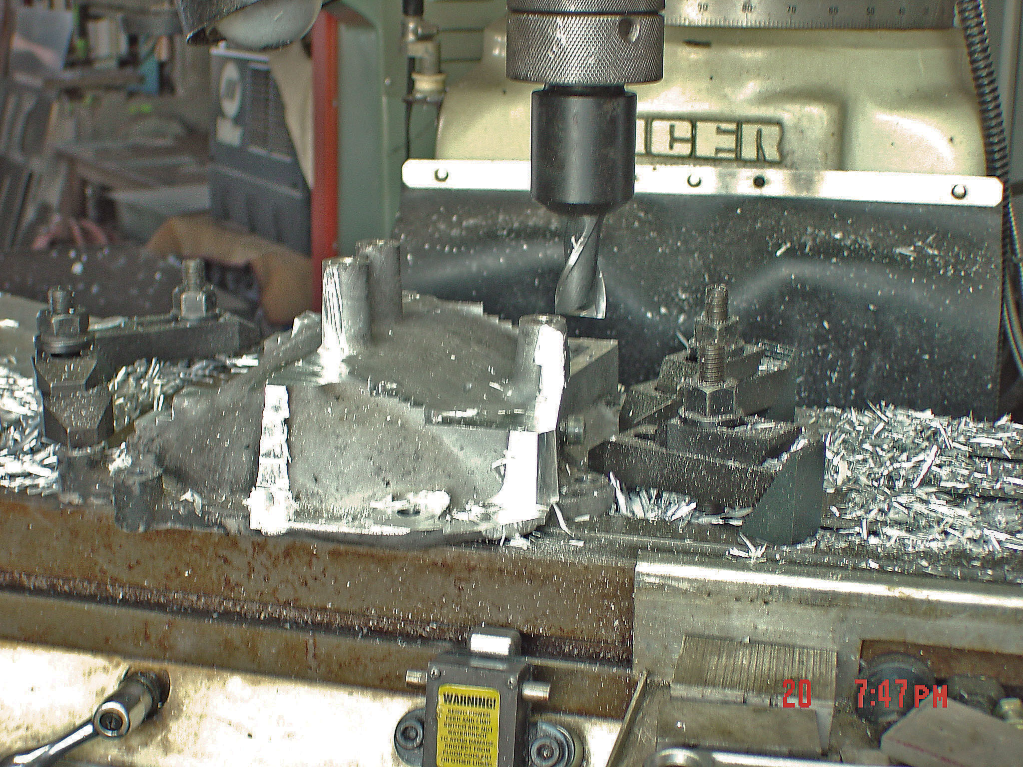
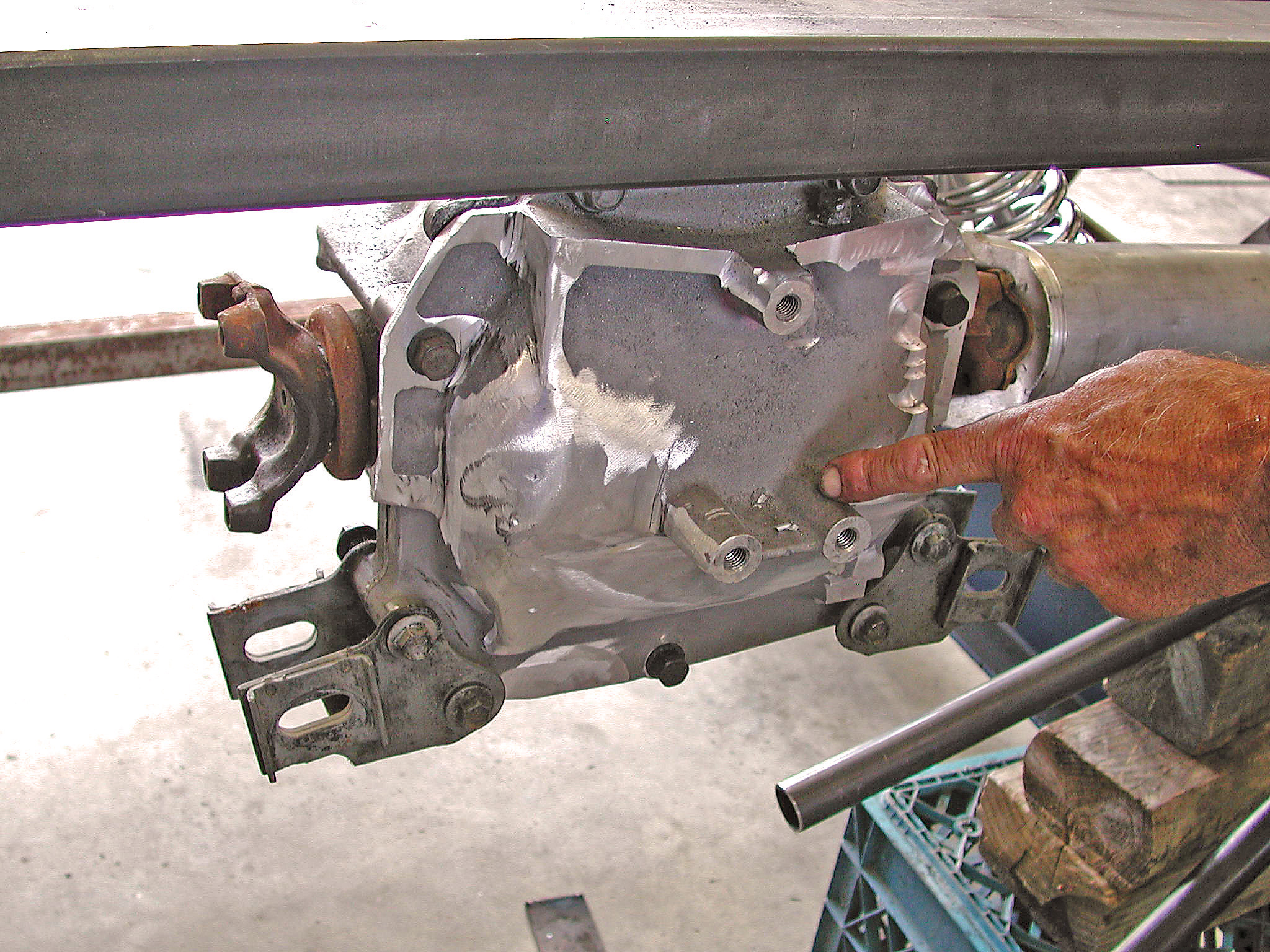
9. With the Corvette C4 aluminum truss work removed, the next step is milling off the old mounting bosses from the backside of the Corvette C4 aluminum-cased gear carrier.
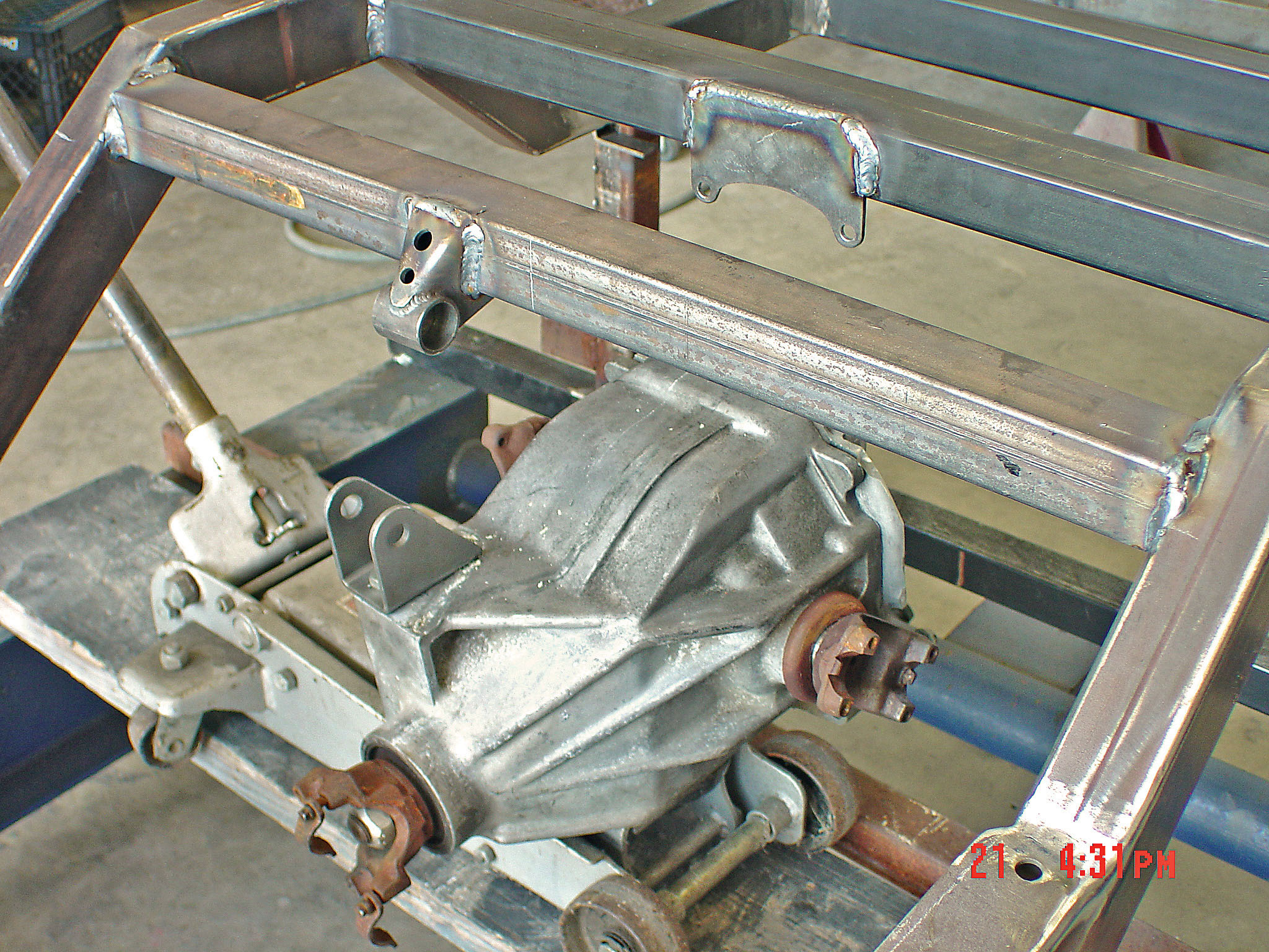
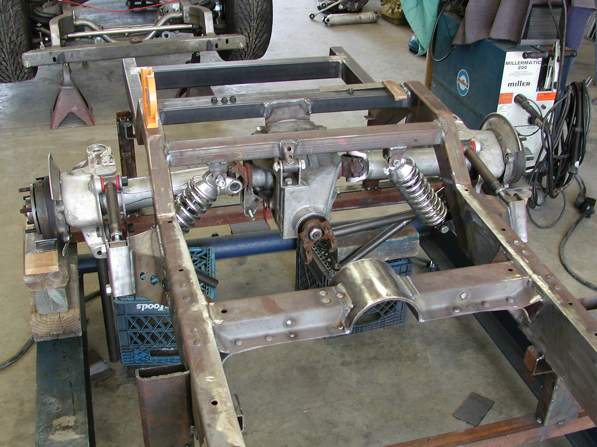
10. Here we see our modified Corvette IRS gear carrier mocked up into place. Note that the Cimbanins have already arrived at the centerline on the modified Flat Out Engineering crossmember support brace and have welded into the chassis.
11. Shown is the mockup of the passenger’s-side IRS using the rear control arm boxes from the Flat Out Engineering kit.
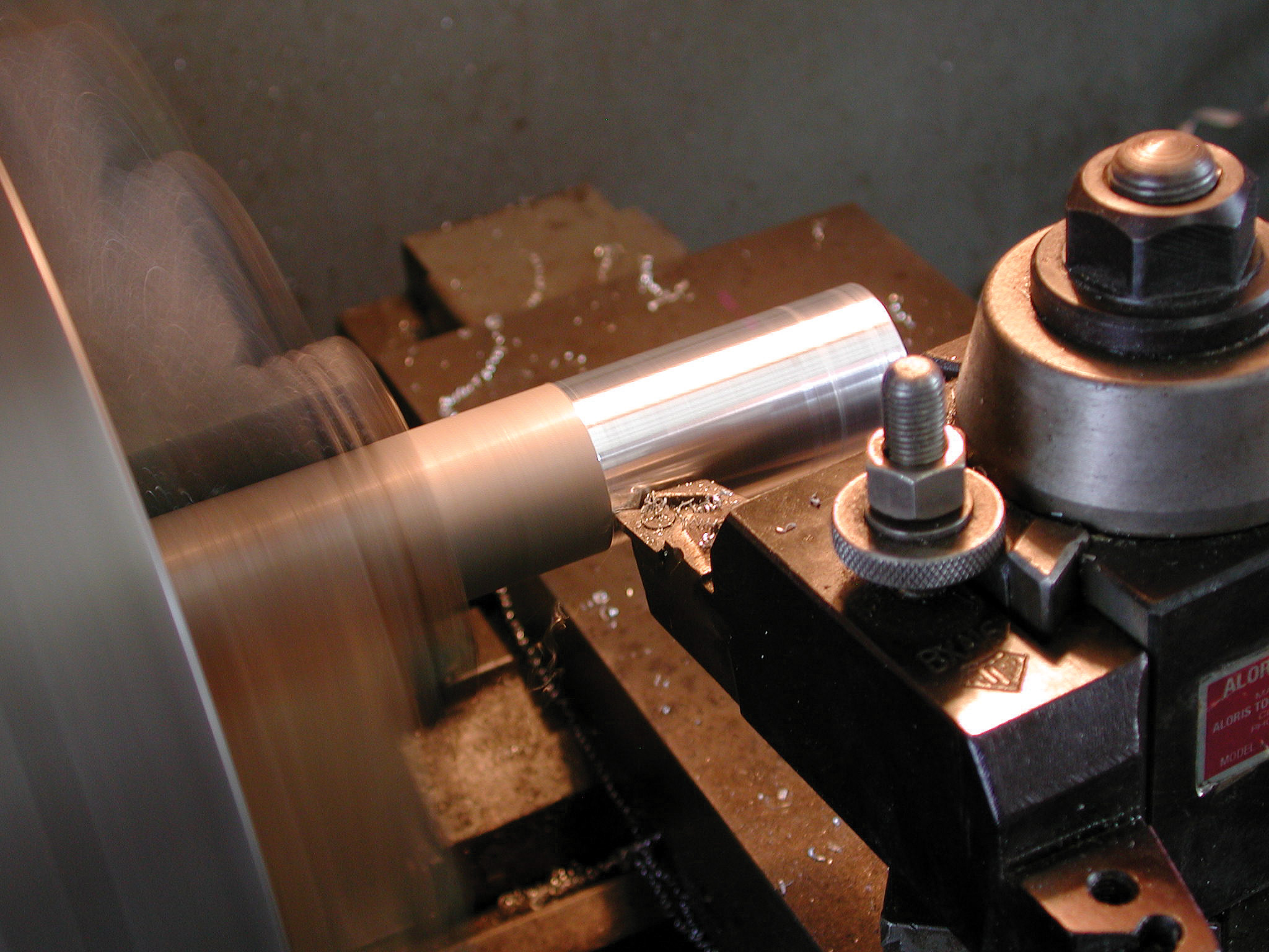
12. To suit the requirements of this chassis, the Corvette C4 half shafts were narrowed 1-1/2 inches.
13. Also shown are the fully adjustable 4130 chromoly upper and lower adjustable control arms, measuring 11 inches top and 13 inches bottom. These arms are equipped with red Energy Suspension polyurethane bushings.
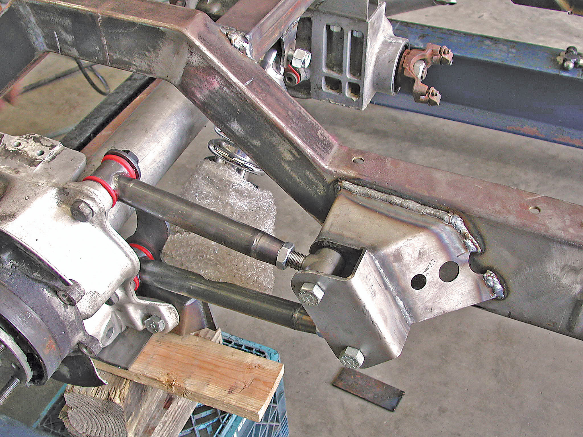
14. Here we see the new upper and lower control arms bolted up to the C4 hub carrier and the Flat Out Engineering control arm mounting bracket.
15. Shown are the OE torque arm mounting brackets bolted up to the Corvette gear carrier. These will be replaced by a custom set fabricated by Cimtex.
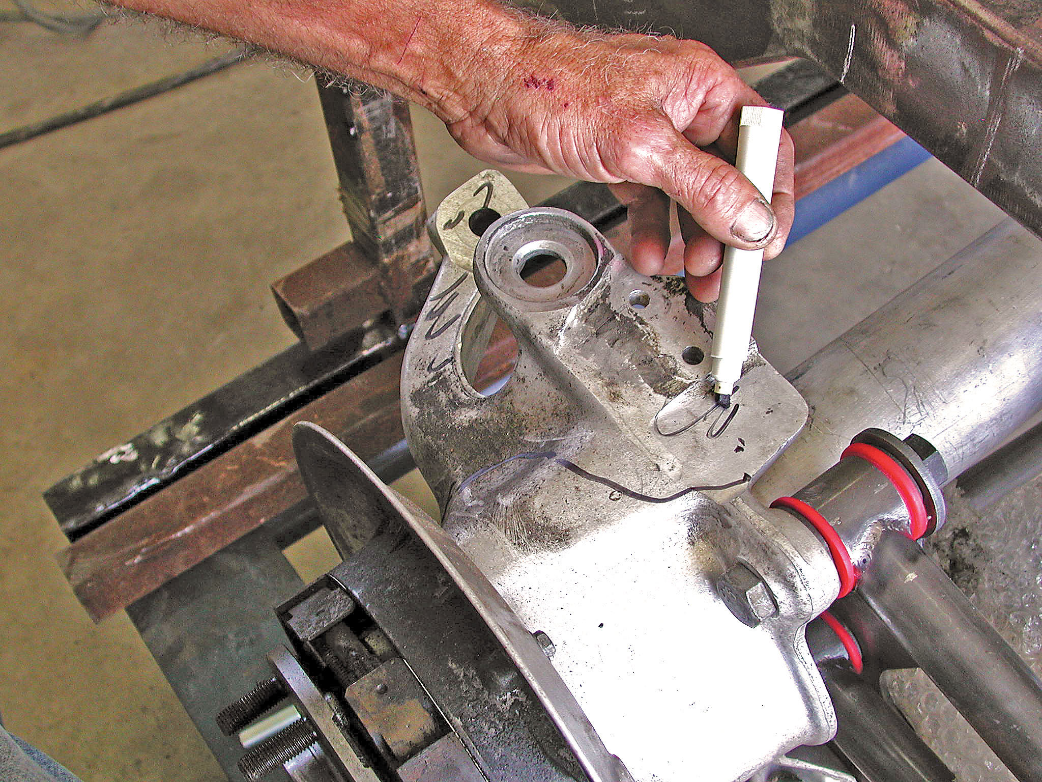
16. Darrell scribes the area where the old truss work used to attach to the C4 hub carrier assemblies. This excess material will all be milled off by the time the finished product hits the show circuit.
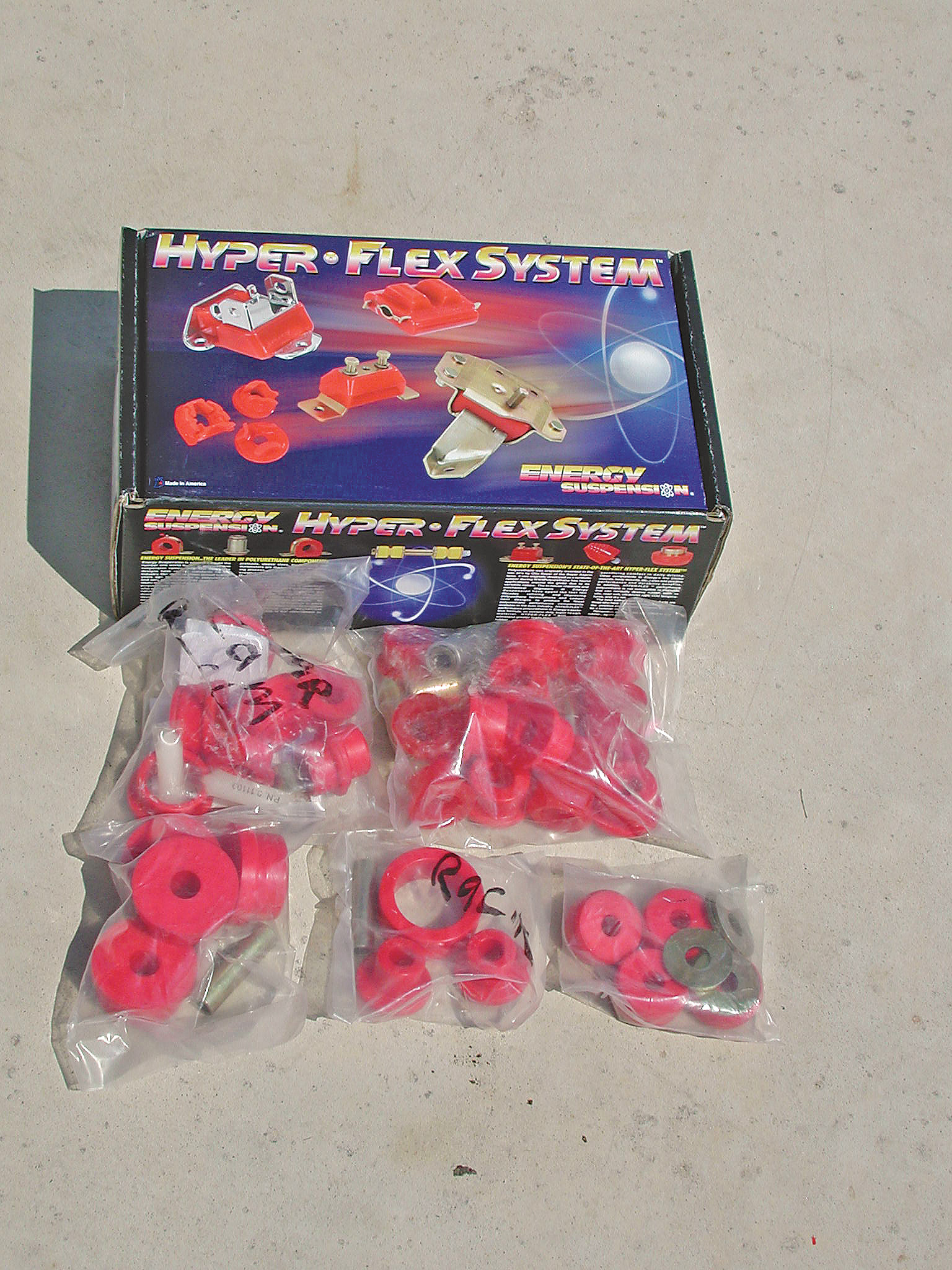
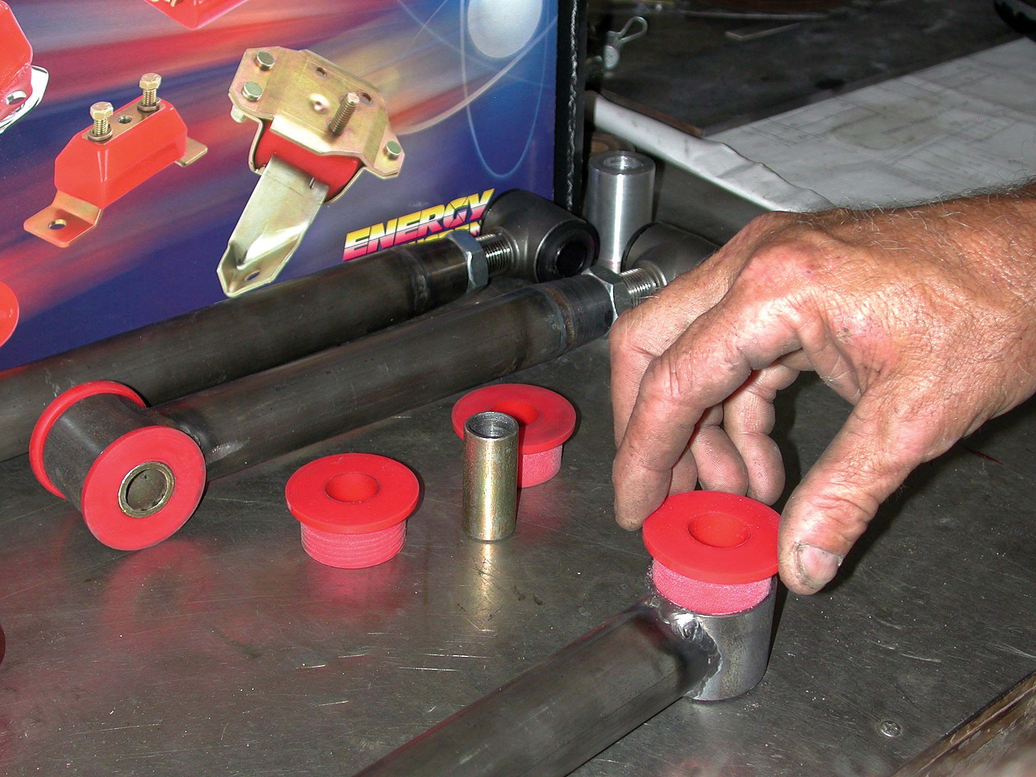
17. For this build we’re using an Energy Suspension Hyper-Flex polyurethane bushing kit (red) on all crucial suspension pickup points on the chassis.
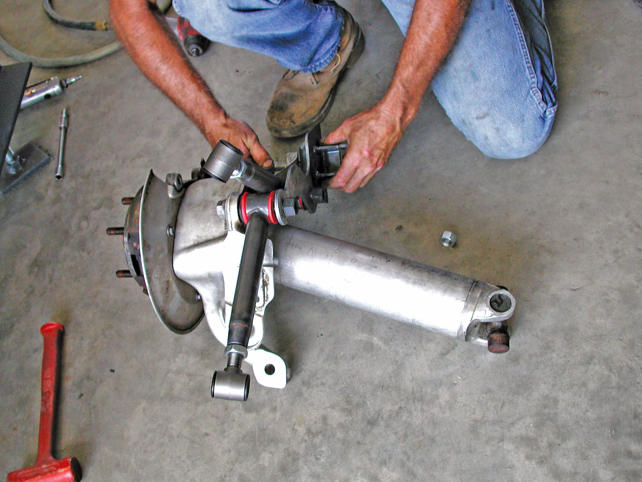
18. Here we see Darrell mocking up the new chromoly torque arms to the passenger’s side of the Corvette IRS.
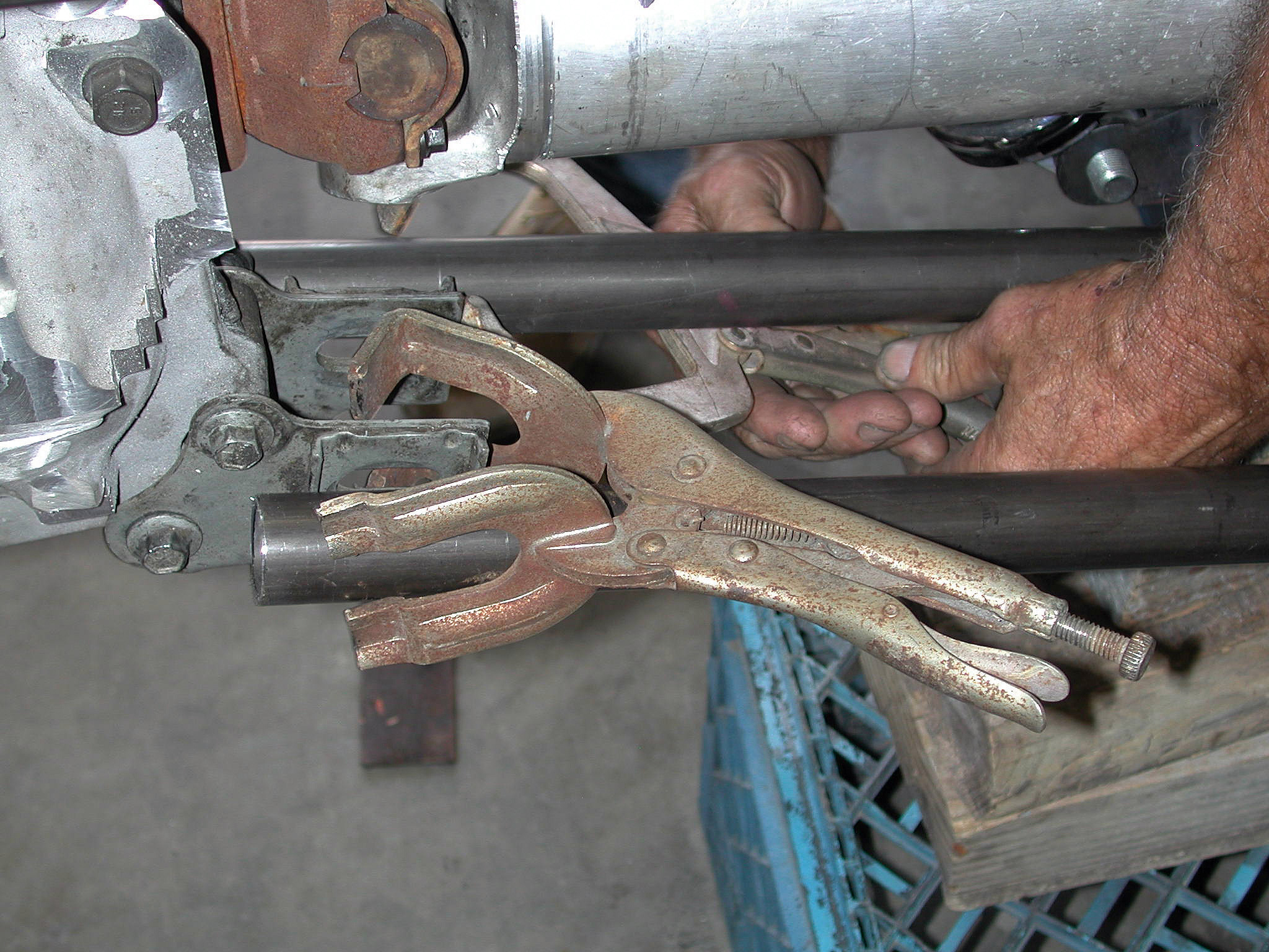
19. Once it has been sized, Darrell installs the Energy Suspension polyurethane suspension bushings and sleeves, using a little Teflon grease to help make the going easier.
20. With the passenger’s side of the IRS all mocked up, Darrell can tackle the driver’s side with confidence.
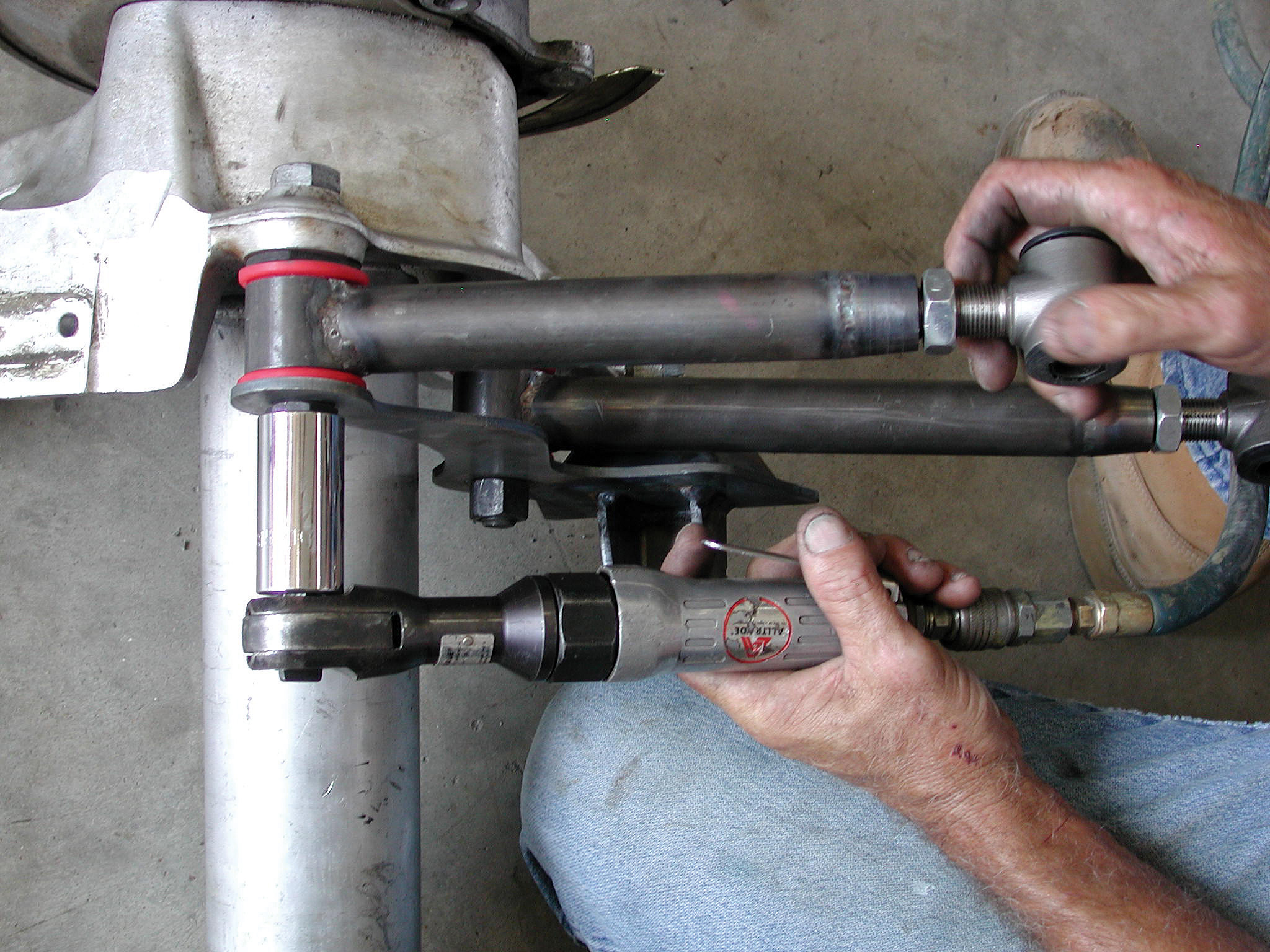
21. This overhead view shows Darrell bolting up the rear control arms, using a Craftsman air wrench and a 5/8-inch nut.
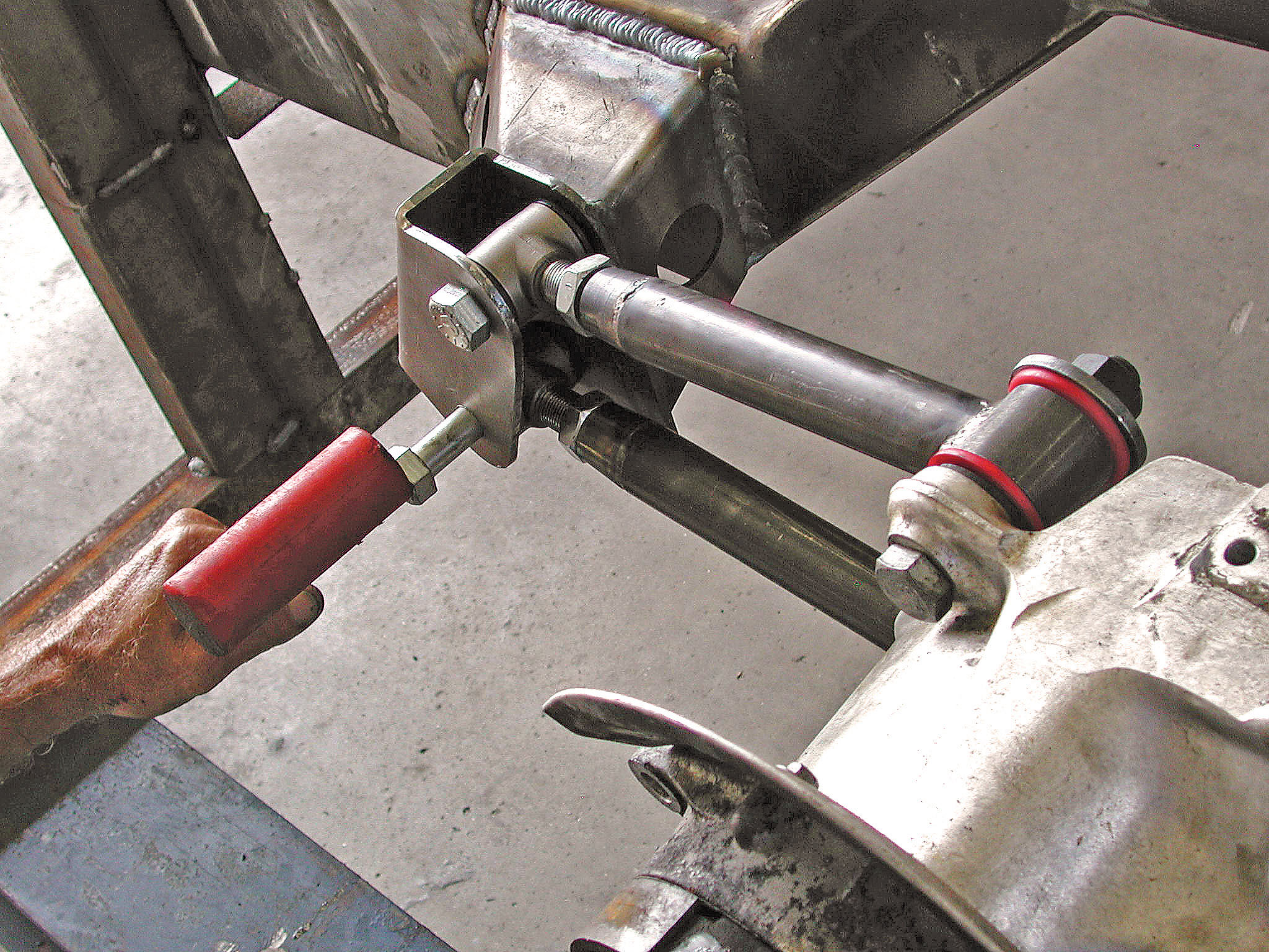
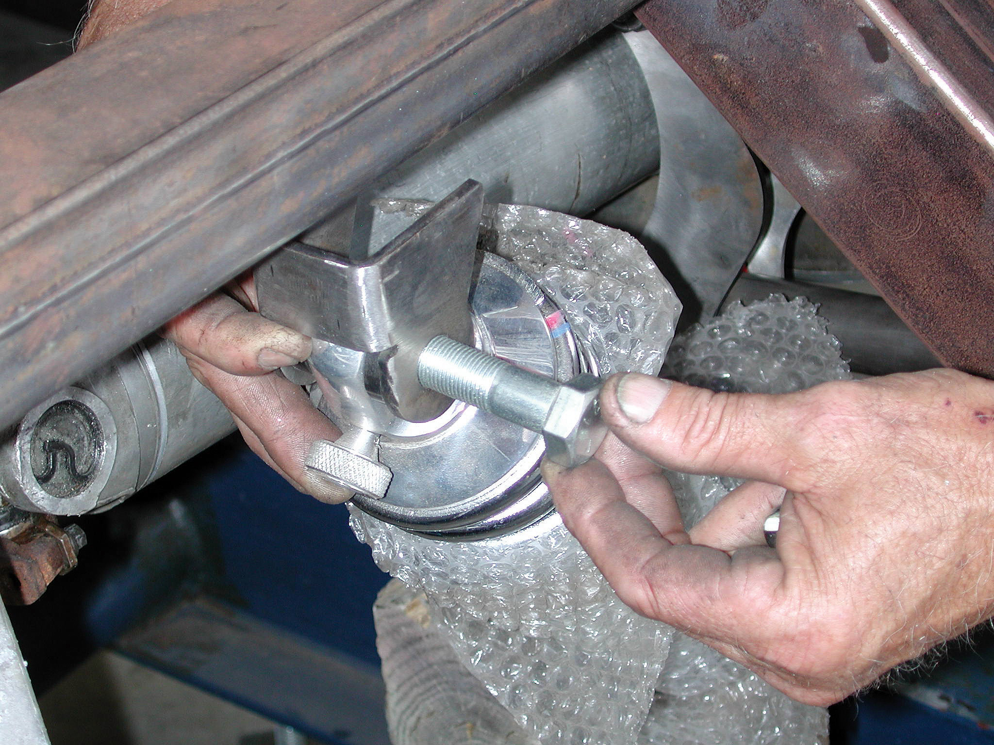
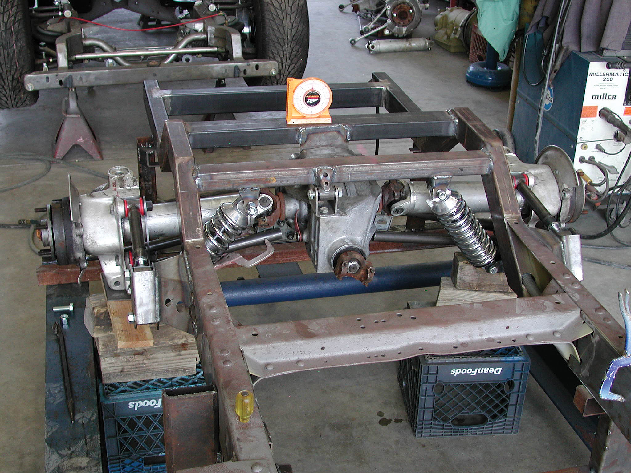
22. With the rear suspension roughed into place, Darrell installs the Flat Out Engineering upper shock bracket onto the Aldan Eagle coilover shock.
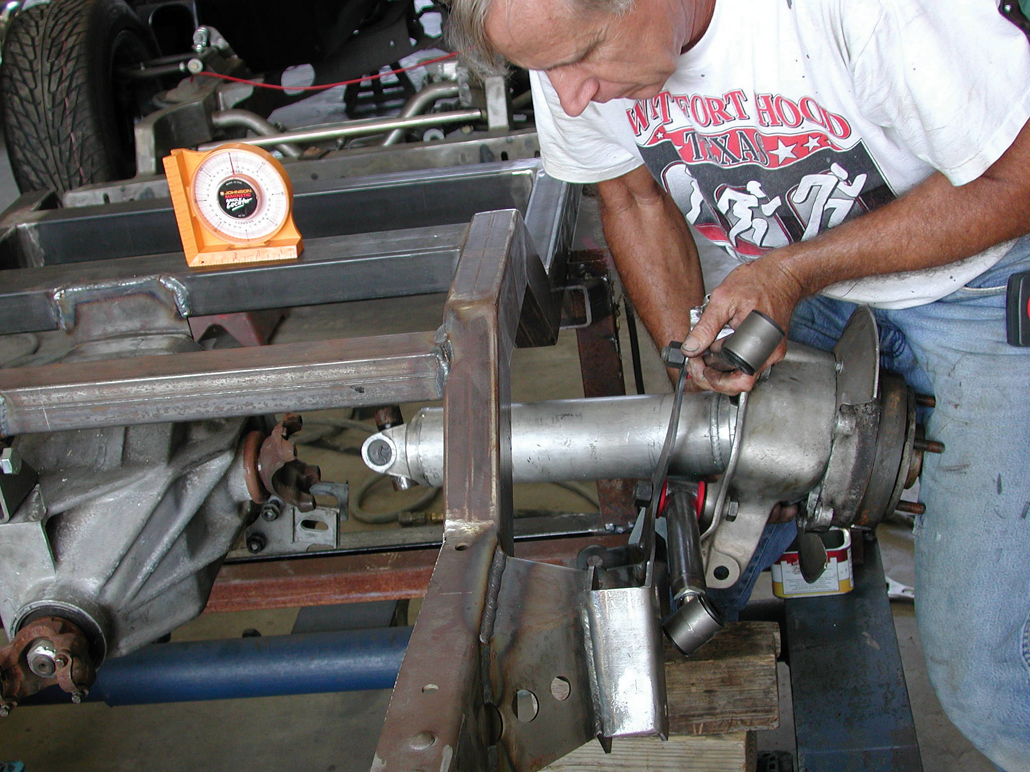
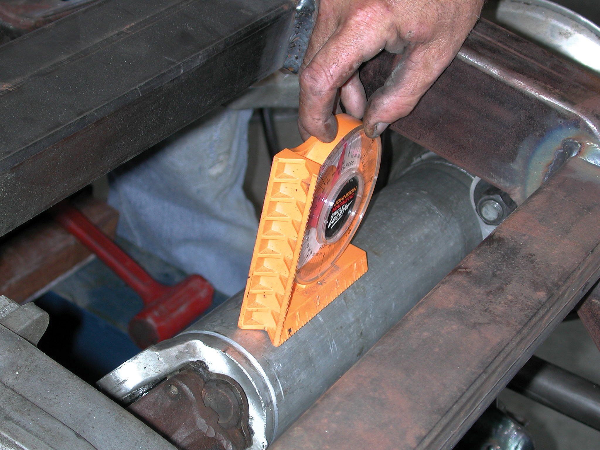
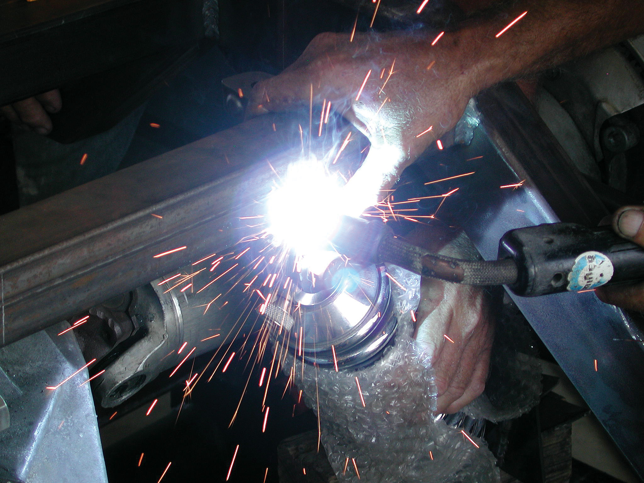
23-24. An angle finder is used to find the neutral position of the Corvette C4 half shaft. Once this setting has been achieved, Darrell welds the bracket to the modified Flat Out Engineering rear crossmember.
23-24. An angle finder is used to find the neutral position of the Corvette C4 half shaft. Once this setting has been achieved, Darrell welds the bracket to the modified Flat Out Engineering rear crossmember.
25. Here we see Darrell fabricating one of the rear torque arms for the driver’s side of the suspension.
26. Proper spacing of these torque arms is achieved with a set of custom-machined aluminum spacers measuring 1-3/4x1-7/8 inches.
27. Obviously, this is a much nicer setup than the original Corvette C4 cast-aluminum truss work.
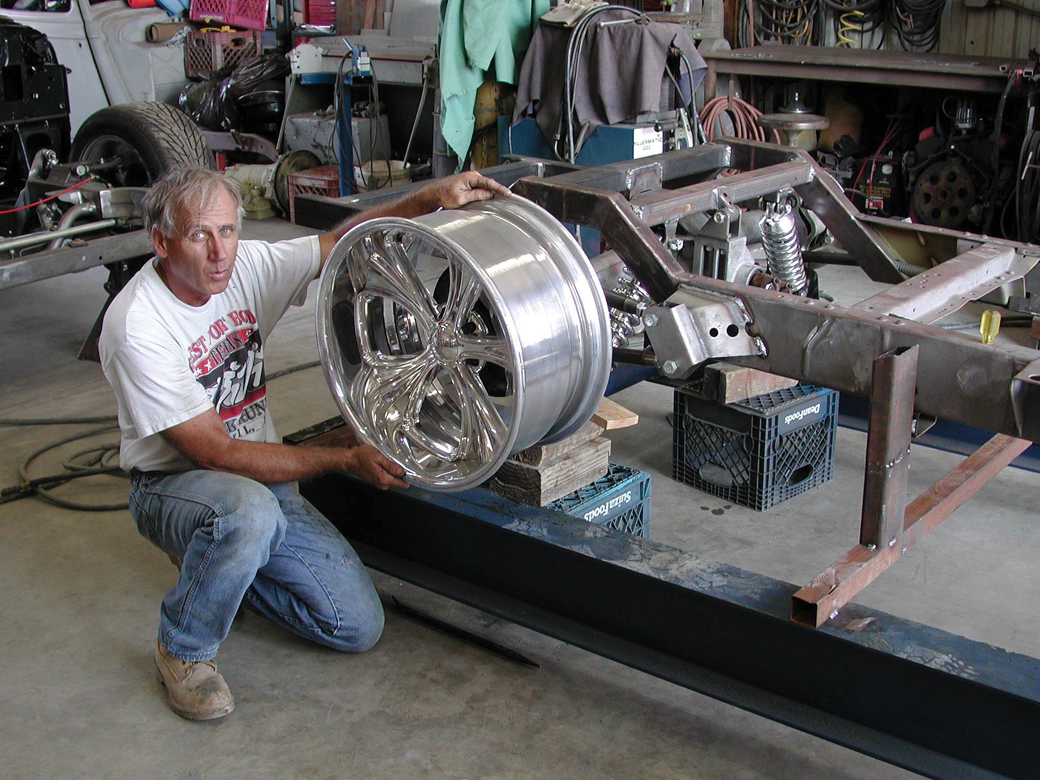
28. Darrell test fits a 20x10-inch billet wheel to check the spacing. As of this writing, our truck should roll off the chassis jig wearing a set of Intro billet wheels and BFGoodrich radial T/A tires.
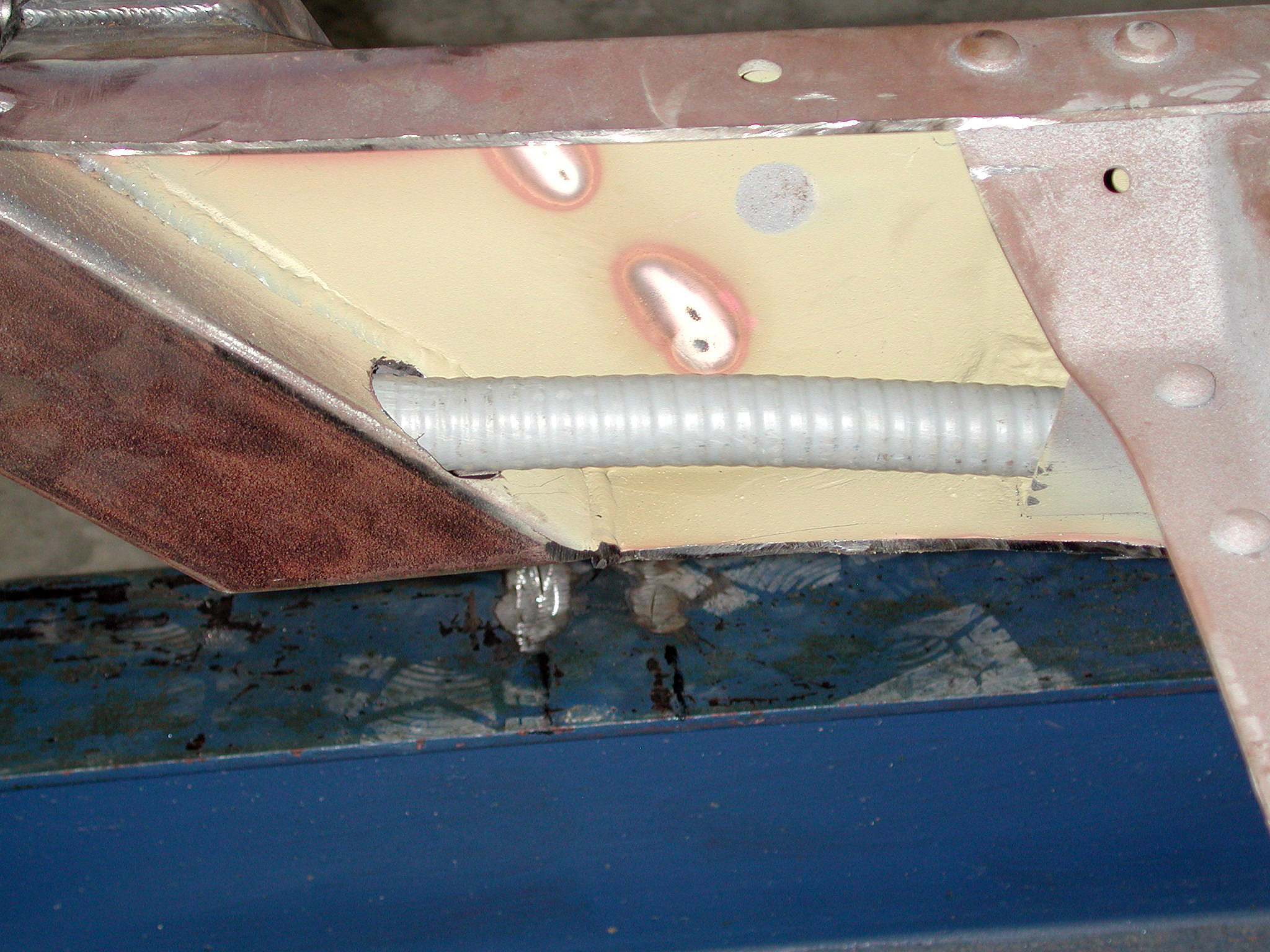
29. Shown is the length of Romex electrical cable that the Cimbanins have routed through both sides of the chassis. Brake and fuel lines will run through the driver’s side, while electrical lines will run through the passenger’s side.
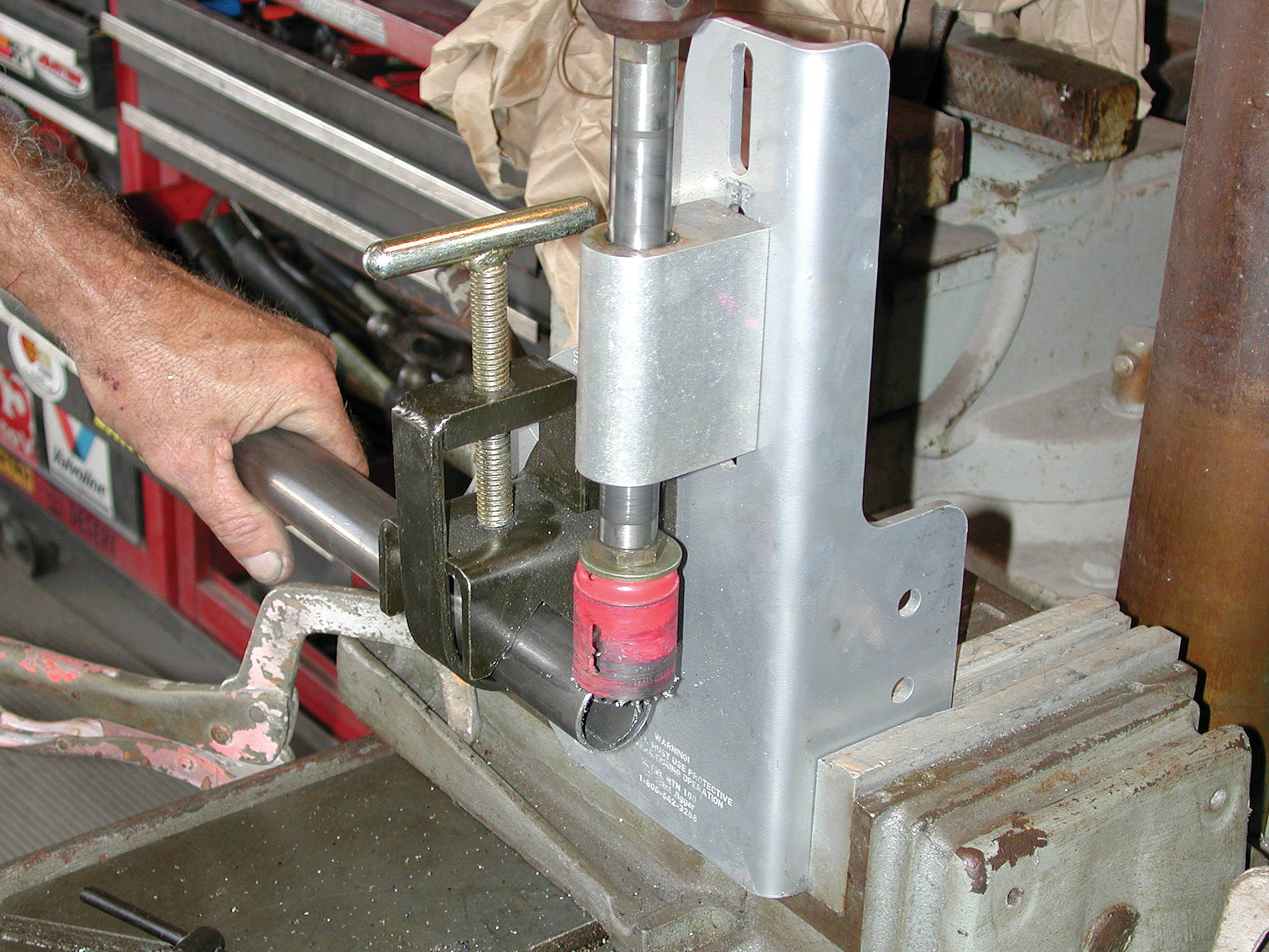
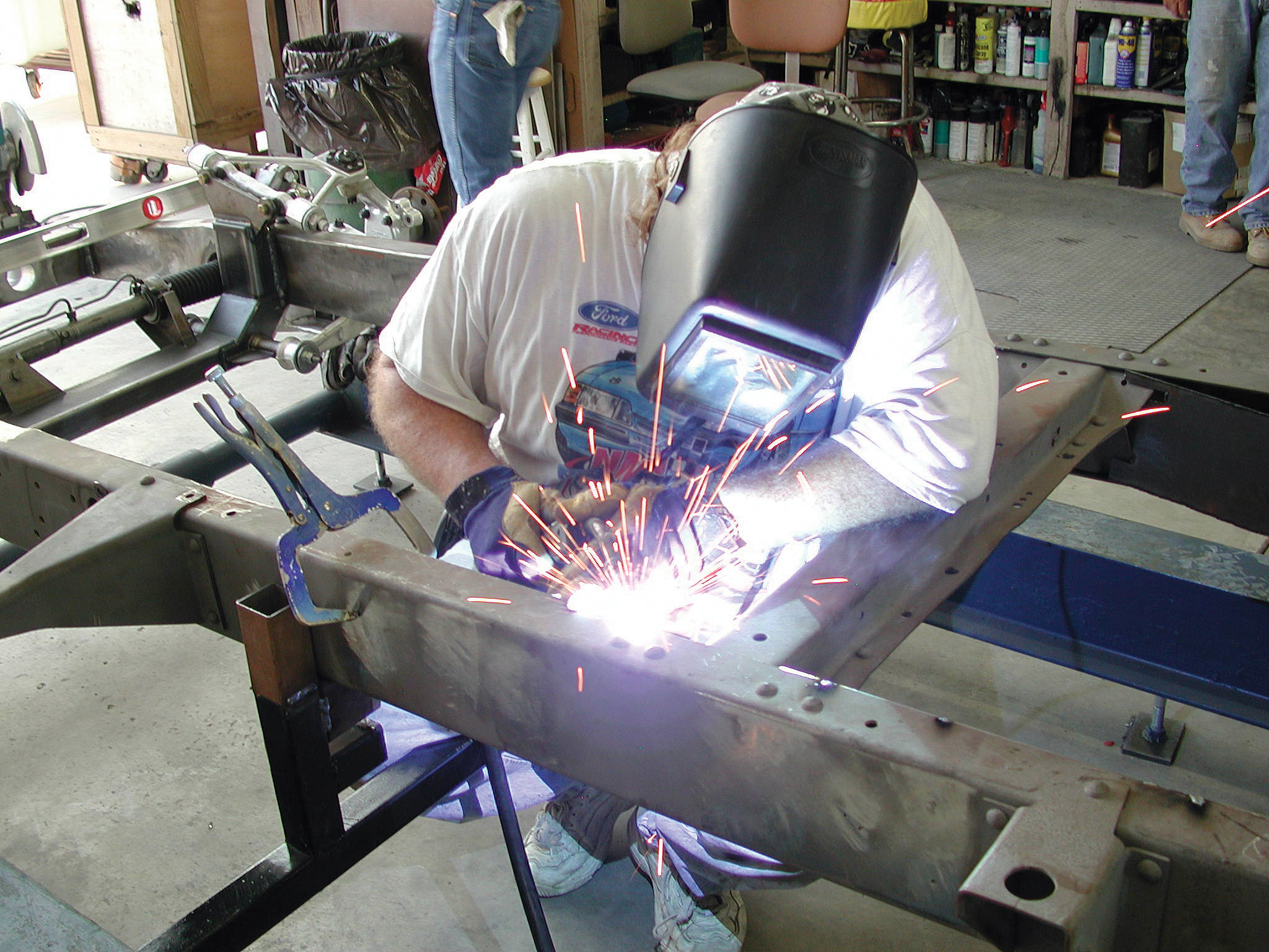
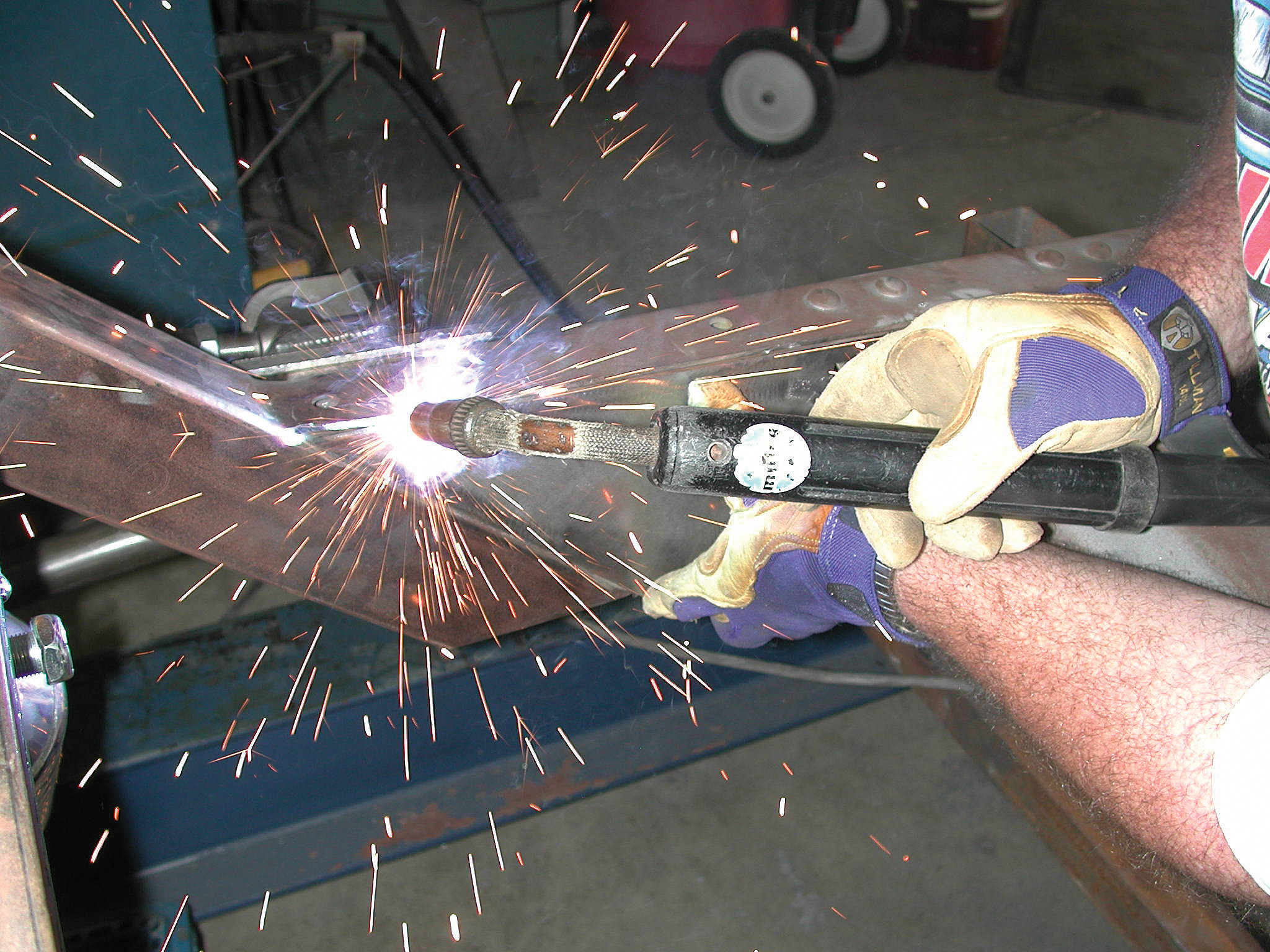
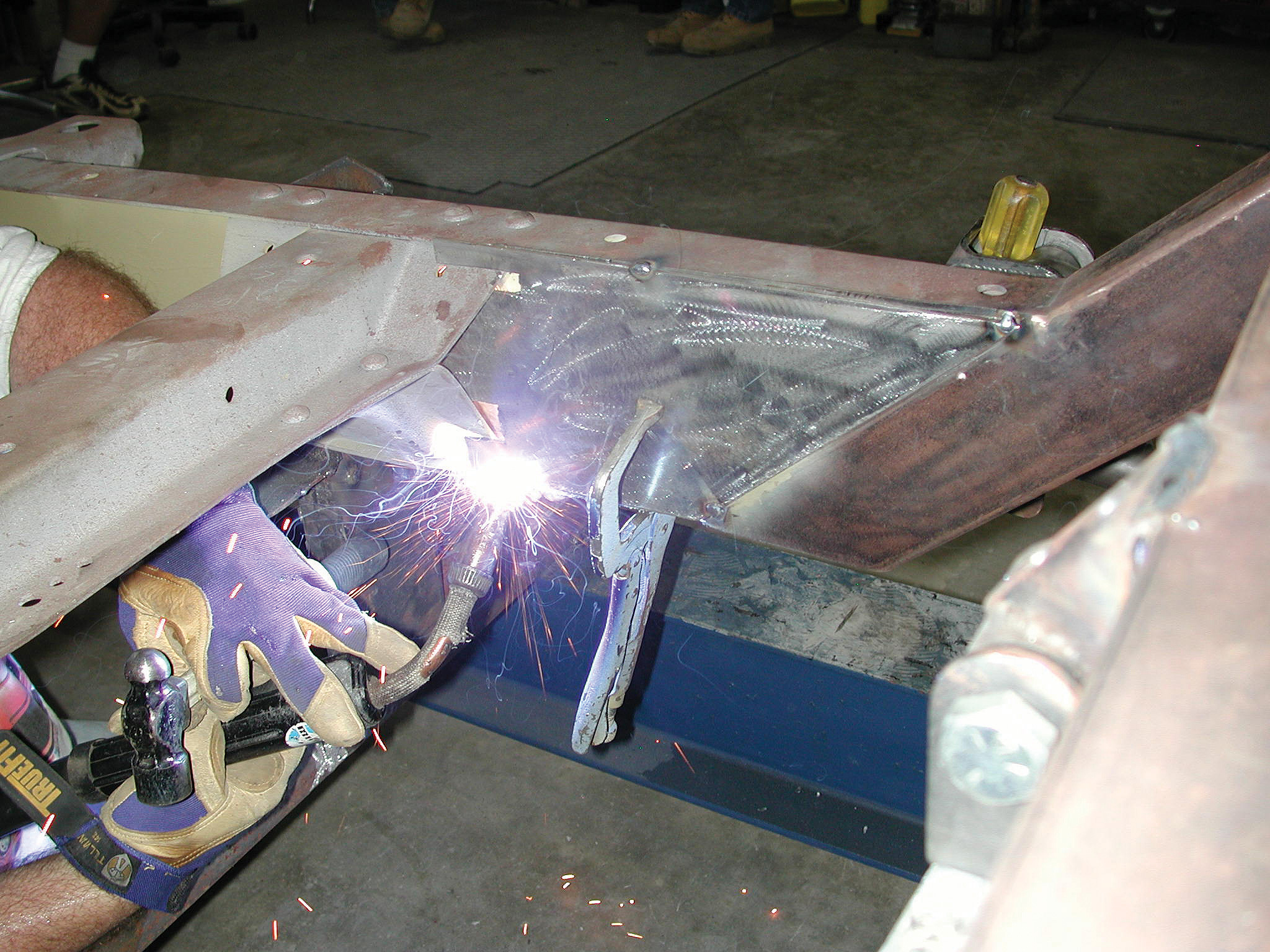
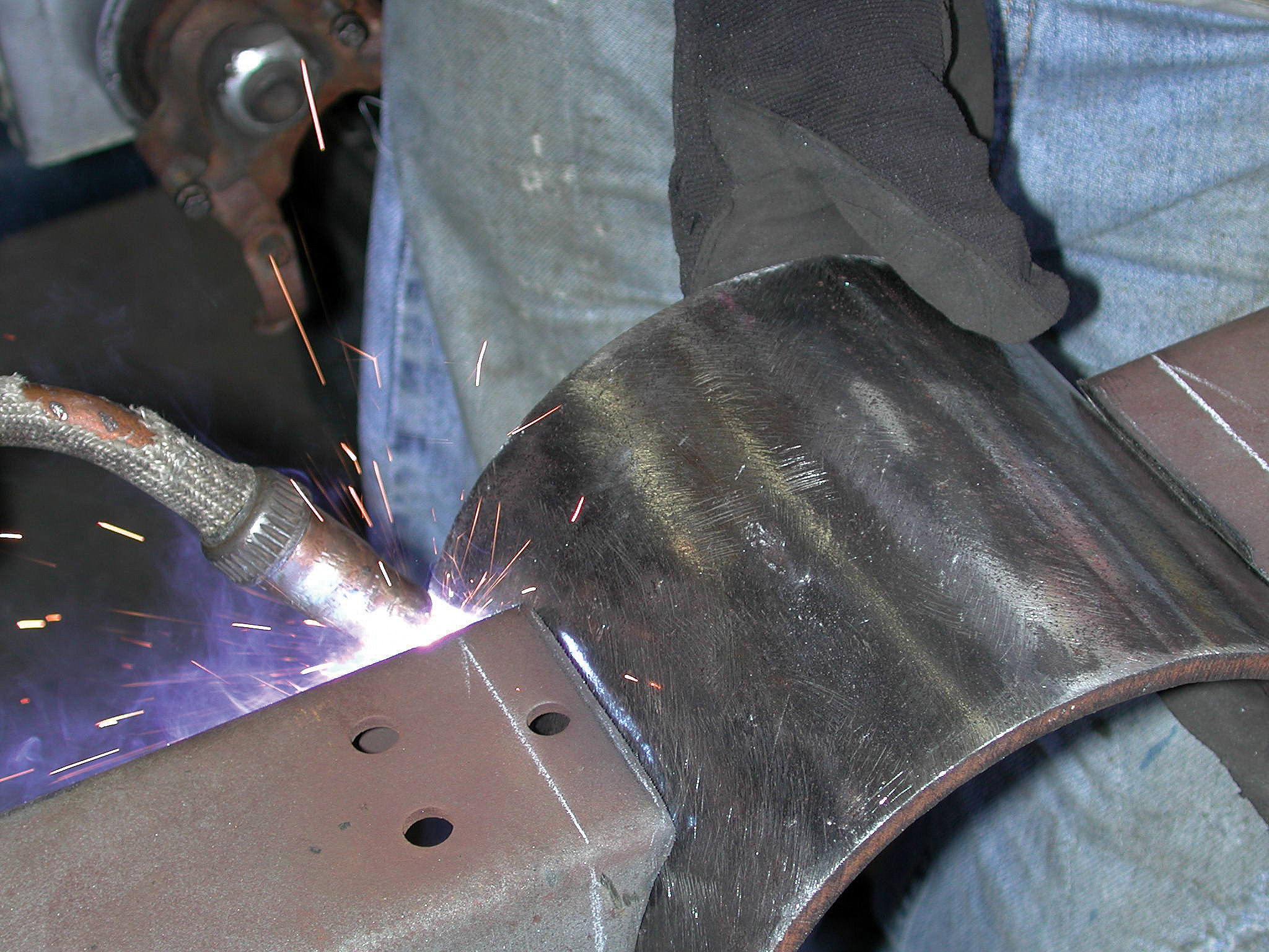
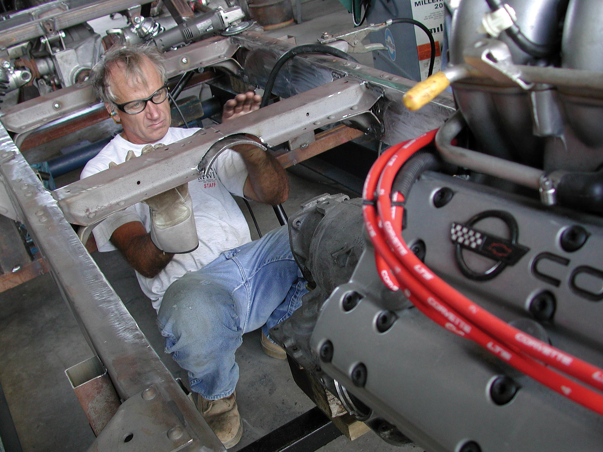
30-33. Cimtex Rods metal fabricator Billy Walker is seen installing the remainder of the boxing plates onto the rear of the chassis. These plates were first tacked up and then final welded in place.
30-33. Cimtex Rods metal fabricator Billy Walker is seen installing the remainder of the boxing plates onto the rear of the chassis. These plates were first tacked up and then final welded in place.
30-33. Cimtex Rods metal fabricator Billy Walker is seen installing the remainder of the boxing plates onto the rear of the chassis. These plates were first tacked up and then final welded in place.
30-33. Cimtex Rods metal fabricator Billy Walker is seen installing the remainder of the boxing plates onto the rear of the chassis. These plates were first tacked up and then final welded in place.
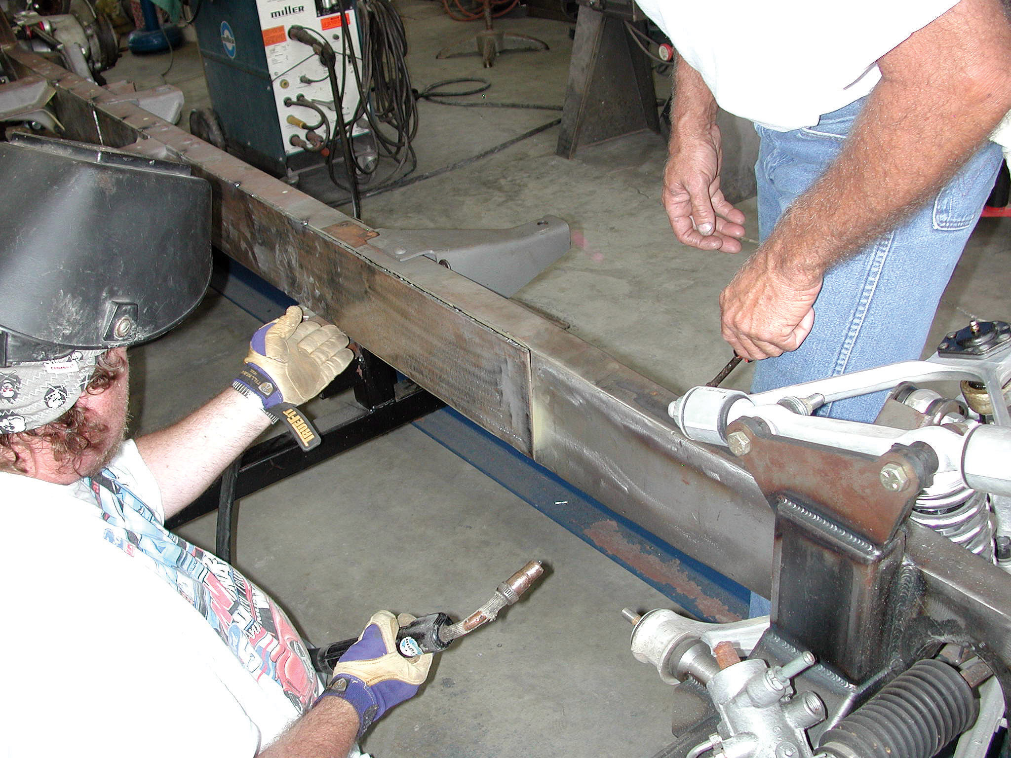
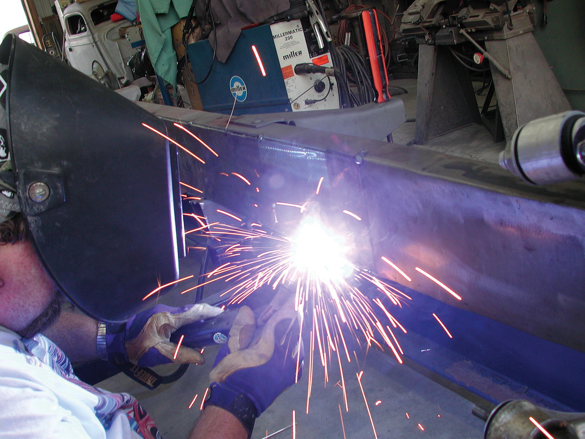
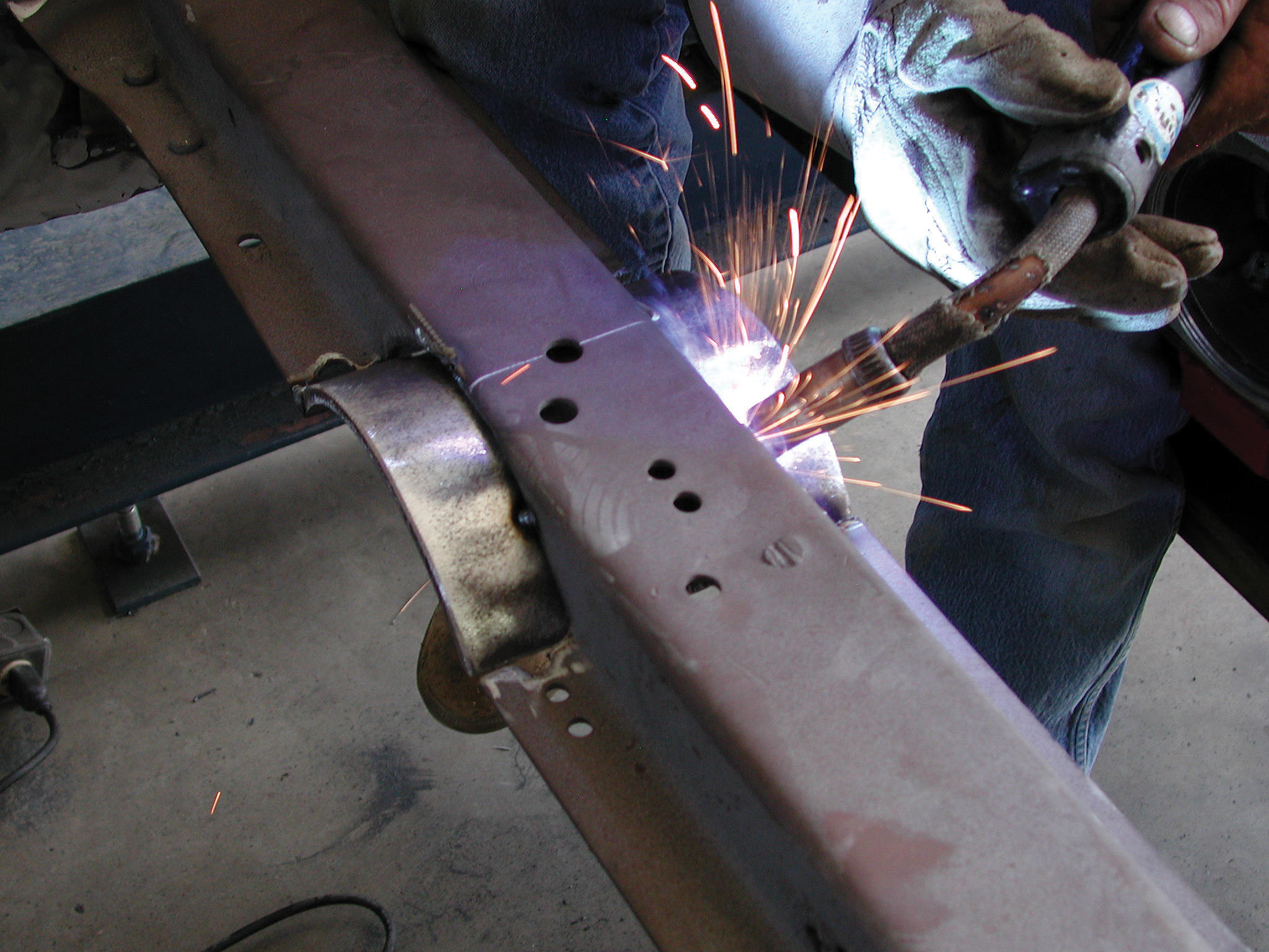
34-35. Welding up the two rectangular boxing plates at the rear of the new framerails signifies that this lengthy part of the job is done!
34-35. Welding up the two rectangular boxing plates at the rear of the new framerails signifies that this lengthy part of the job is done!
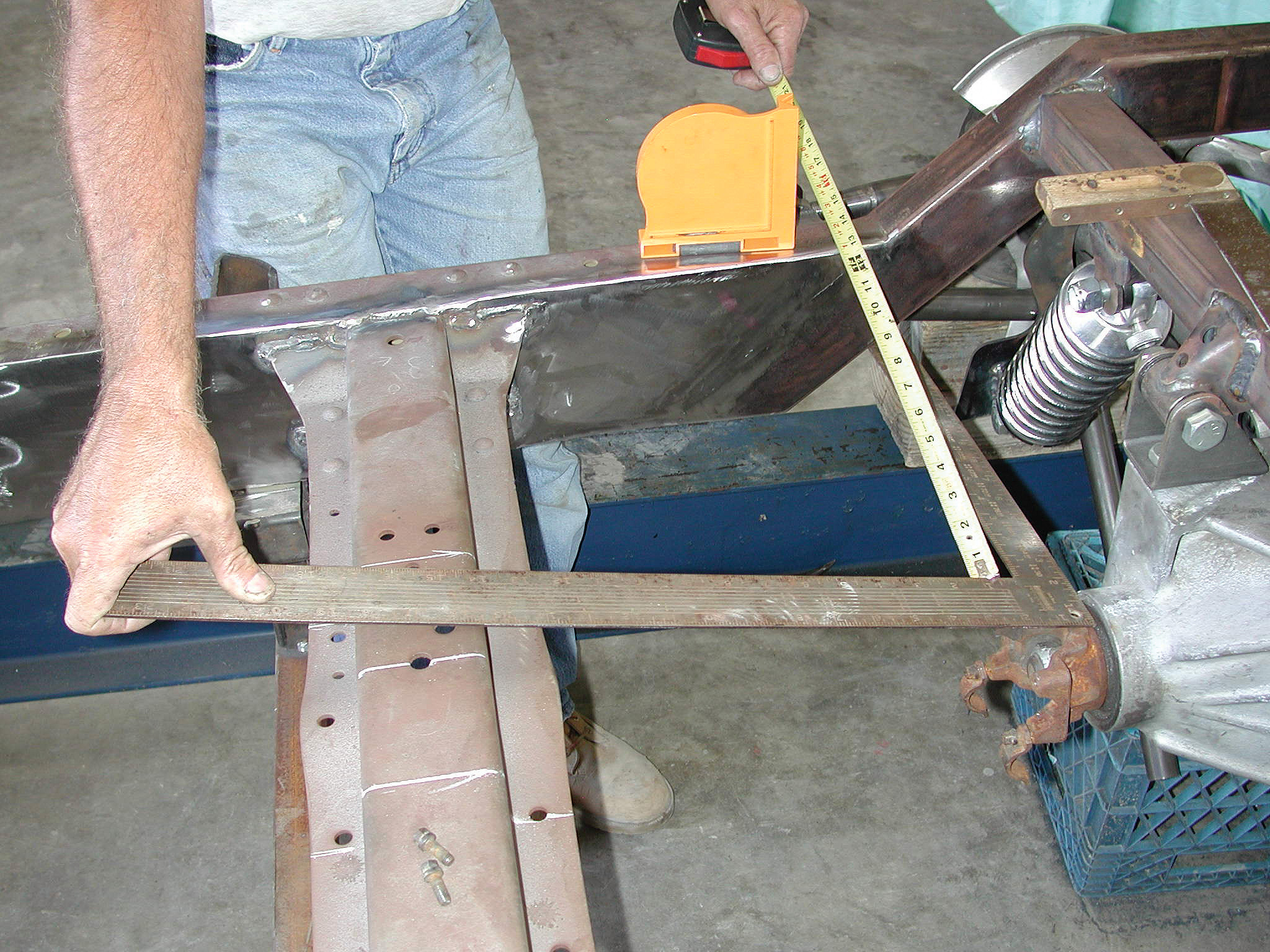
36-37. Darrell starts setting up the driveshaft loops. First he locates the centerline of the rear crossmember, and then he checks it for squareness.
36-37. Darrell starts setting up the driveshaft loops. First he locates the centerline of the rear crossmember, and then he checks it for squareness.
38. Darrell locates a piece of 3/8-inch steel pipe measuring approximately 3x6 inches. After it has been cut in half, a 4-inch-high section will be used for the center rear crossmember.
39-40. Darrell uses his Craftsman plasma cutter to trim away the unnecessary material from the center rear crossmember. After some initial grinding and trial fitting, he final welds the piece in place.
39-40. Darrell uses his Craftsman plasma cutter to trim away the unnecessary material from the center rear crossmember. After some initial grinding and trial fitting, he final welds the piece in place.
41. Here’s how the modified rear crossmember looks once it’s fully installed.
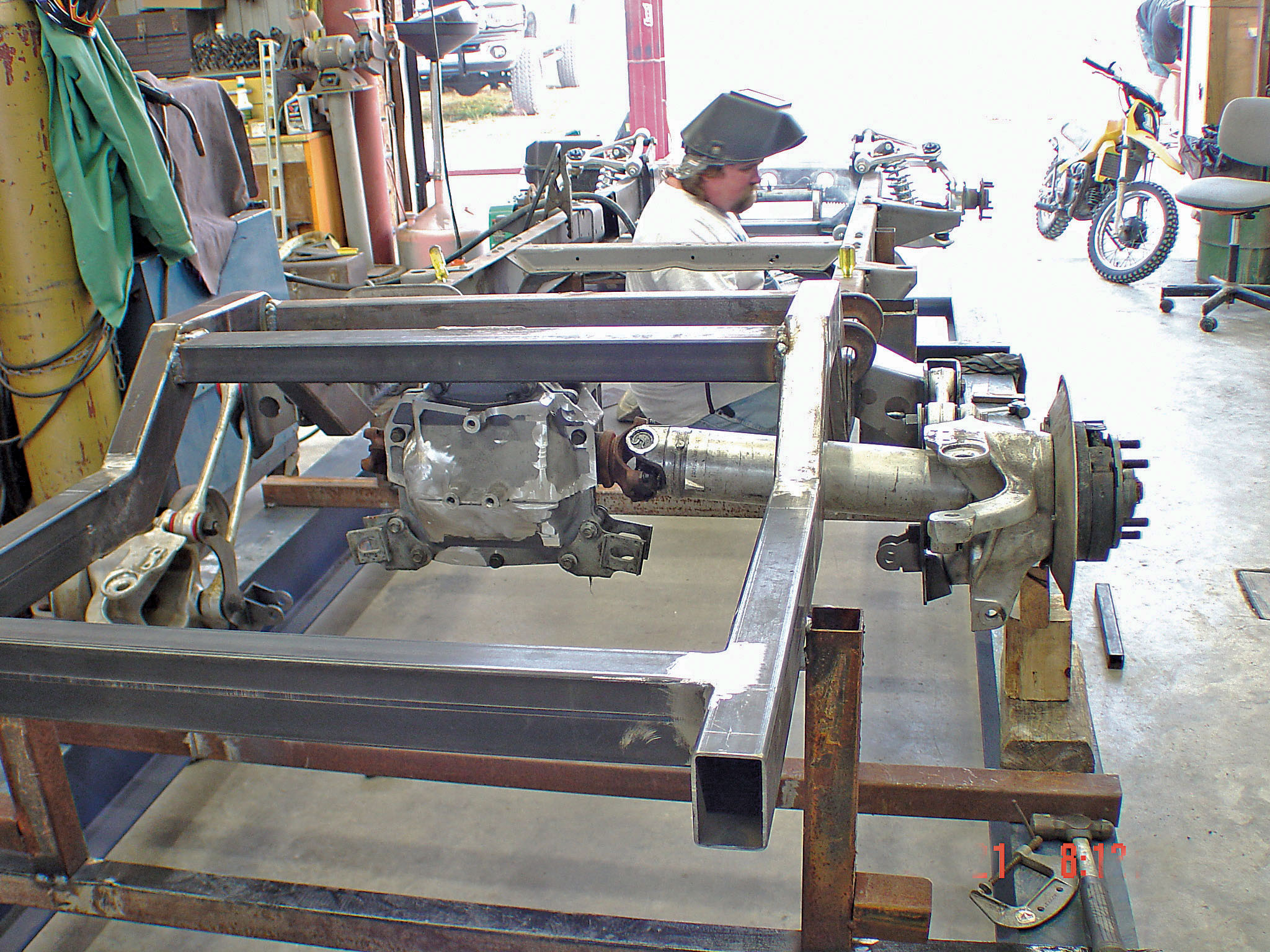
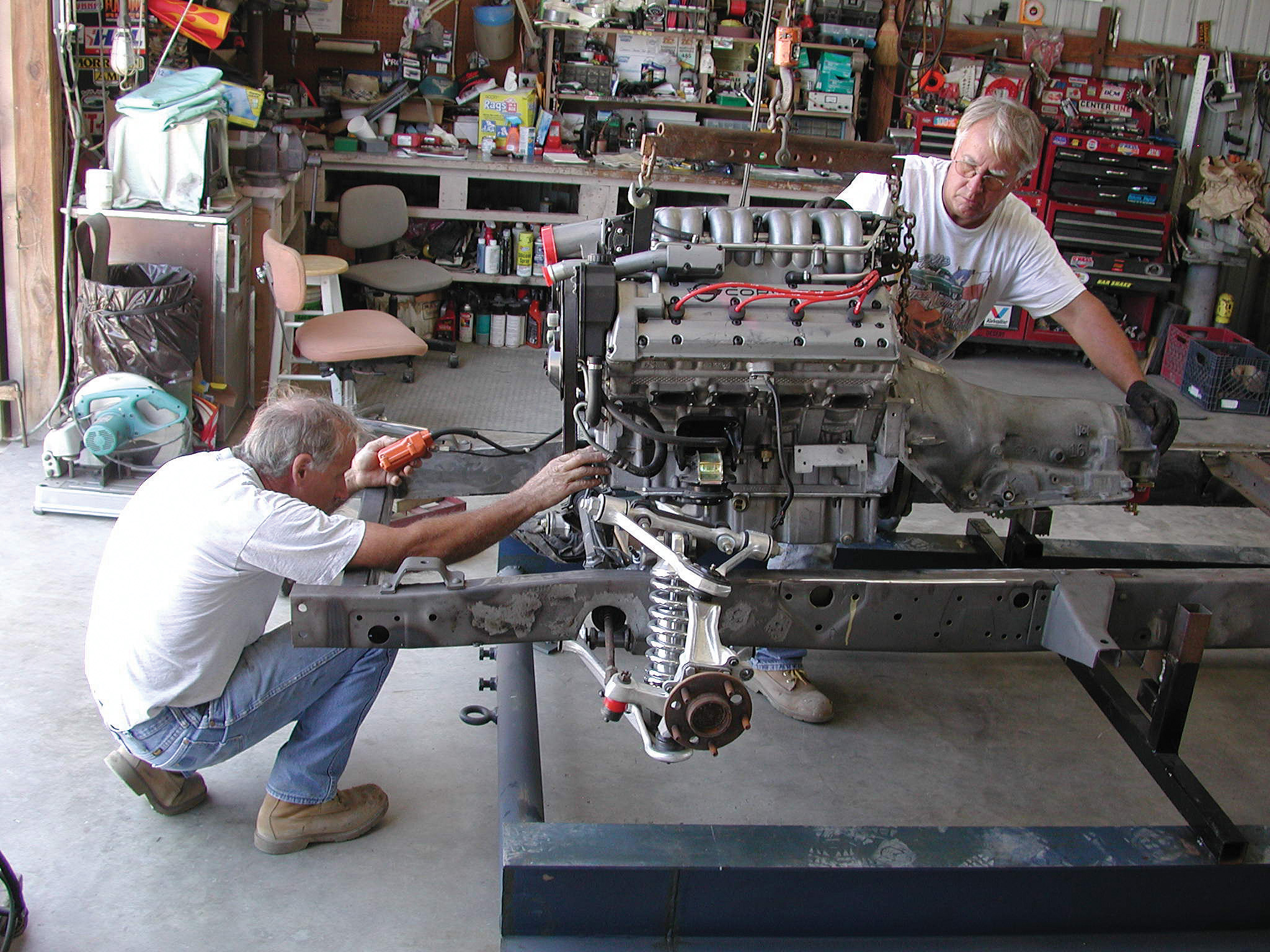
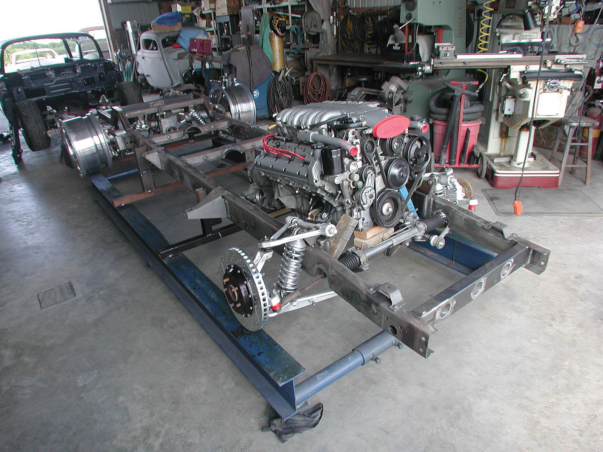
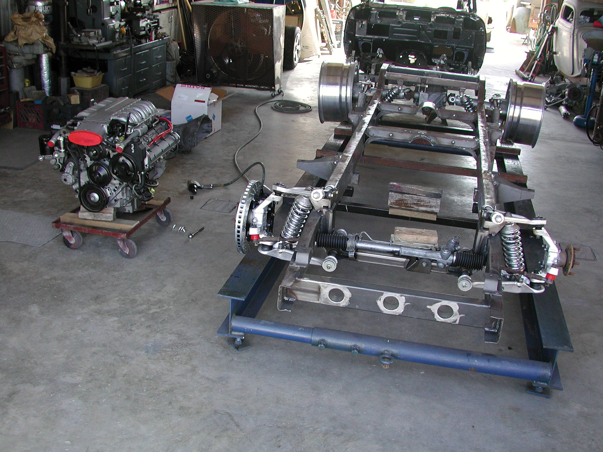
42-43. The Cimbanins trial fit their new ZR1 Corvette engine and Jimmy G. 4L80E slush box into the highly modified ’56 Cameo chassis.
42-43. The Cimbanins trial fit their new ZR1 Corvette engine and Jimmy G. 4L80E slush box into the highly modified ’56 Cameo chassis.
44-45. With the new ZR1 engine and trans combo mocked up in the chassis, Darrell is able to visualize the driveshaft angle in relation to the forward crossmember and makes the appropriate modifications. A 2-inch loop is all that’s needed on the front center crossmember.
44-45. With the new ZR1 engine and trans combo mocked up in the chassis, Darrell is able to visualize the driveshaft angle in relation to the forward crossmember and makes the appropriate modifications. A 2-inch loop is all that’s needed on the front center crossmember.
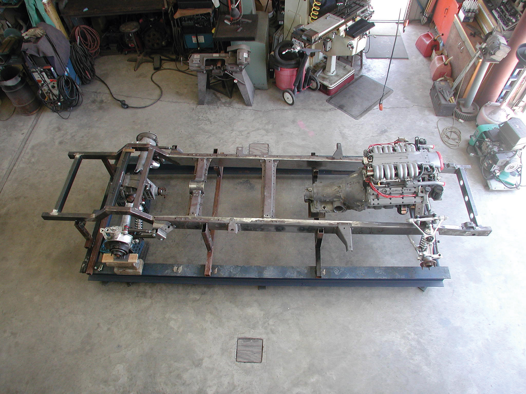
46-47. Here’s the 99-percent completed chassis. It’s a far cry from what the boys at Cimtex Rods started out with, eh?
46-47. Here’s the 99-percent completed chassis. It’s a far cry from what the boys at Cimtex Rods started out with, eh?
ARTICLE SOURCES
Aldan Shock Absorber Co.
22015 S. Avalon Blvd.
Carson, CA 90745
310/834-7478
Baer Brakes
3108 W. Thomas Rd., Ste. 1201
Phoenix, AZ 85017-1411
602/352-1411
Cimtex Rods
P.O. Box 205
Jarrell, TX 76537
512/746-2707
Energy Suspension
1131 Callejon
San Clemente, CA 92673
949/361-3935
Flat Out Engineering
633 W. Katella Ave., Unit K
Orange, CA 92867
(714) 639-2623
