

Edit Template
THE AUTO BUILDER
Menu
Featured

PRODUCT SPOTLIGHT: Stainless Headers’ Chevrolet LS Custom Header Build Kit
Listen up! It’s time to talk about something that’s going to rev up your LS build and have you grinning like a maniac every time you hit the throttle. We’re diving into the nitty-gritty of the Chevrolet LS Custom Header Build Kit, the ultimate solution for anyone looking to unleash the full potential of their LS engine. Buckle up, because this is going to be a wild ride.
Rock Crawling the Sport That Defines Champions
Competitors from across the country converged on Jellico, TN to compete in the Eastern US Nationals held by W.E. ROCK (World Extreme Rock Crawling Series). White Oak, a small community located just outside Jellico, TN is where the event was held. Lil’ Rich, course designer for W.E.ROCK stayed true to his reputation for designing some of the most technical obstacles in the rock crawling world, and Jellico was no exception.
CURE FOR A CLUNKER
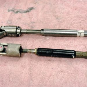
If you are towing your rig with a ’99-’06 General Motors truck, or a Chevy or GMC vehicle, there’s a good chance you have experienced a strange clunking noise when making slow turns. The clunking noise seems to originate from within the steering column, and some owners can actually feel a small vibration in conjunction with the clunking. If you have encountered this problem, it’s not your imagination, as there appears to be a unique conundrum associated with Chevy and GMC pickups, and their corresponding SUVs.


Spotlighter
POPULAR READS
-
Product Spotlight: Bill Mitchell Products Aluminum LS Engine Block
-
PRODUCT SPOTLIGHT: 60-66 Chevy C10 Fresh Air Vent Block Off Plate
-
Product Spotlight: Pyramid Optimized Design Sequential Aurora Taillight for 1964½–1966 Mustang
-
PRODUCT SPOTLIGHT: Cam Covers for GEN/3 Coyote from Pyramid Optimized Design
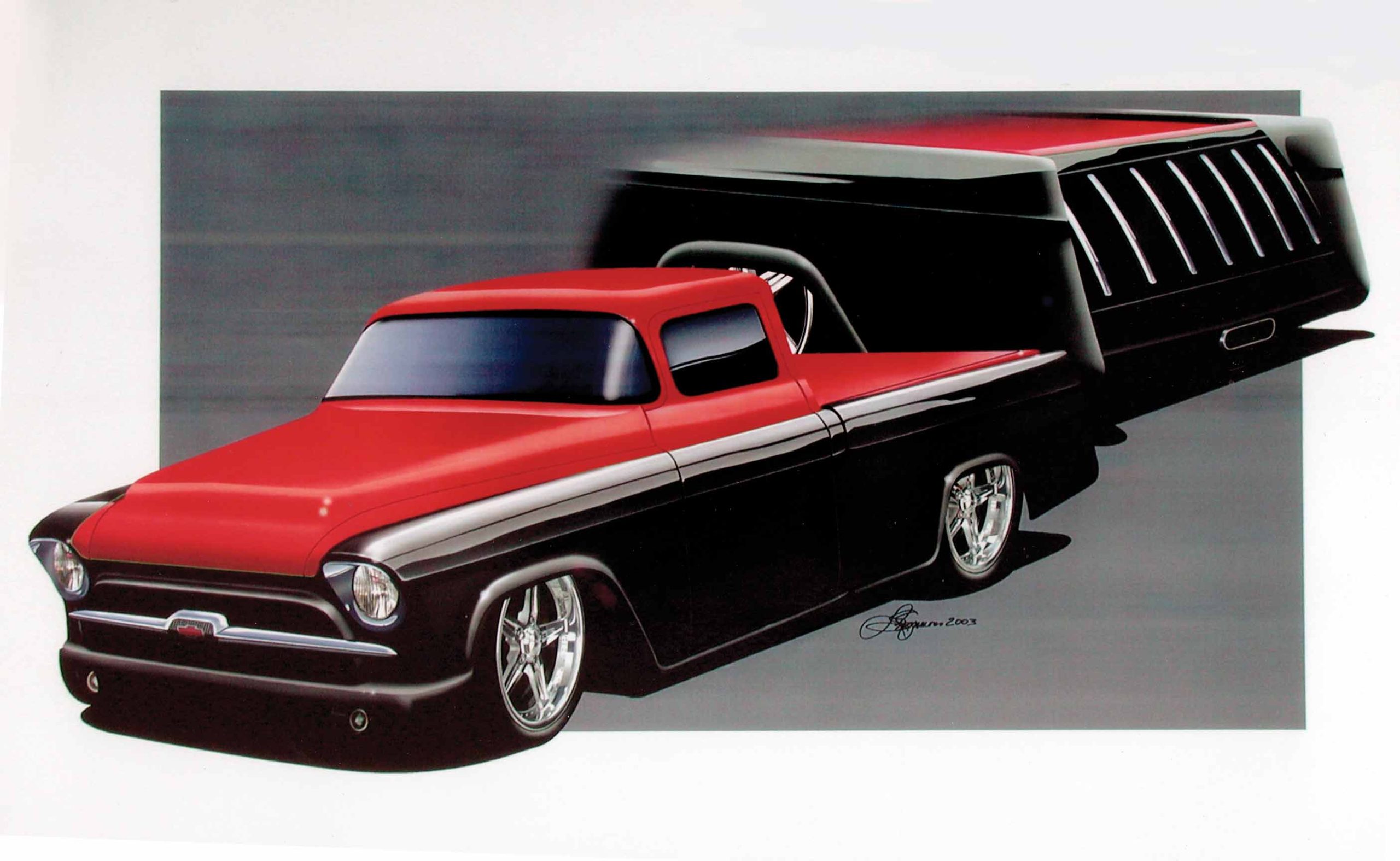
CIMTEX RODS SUPER CAMEO: PART 2
Installing Flat Out Engineering’s Corvette C4 Front Crossmember and Corvette C4 IFS on a 1956 Chevrolet Truck Chassis
Building a good truck chassis is just like building the foundation for a house,” says Cimtex Rods’ Tim Cimbanin. “Everything starts at the ground floor. If you don’t have a good foundation, you don’t have anything!
No truer words were ever spoken, and we’ve been preaching this fundamental information in all our Buckaroo magazines. With that basic thought in mind, Tim and Darrell Cimbanin went about the business of properly setting up the chassis on their latest project, “Super Cameo,” a Corvette ZR1-powered, Corvette C4-suspended, full custom 1956 Chevrolet Cameo pickup. In our December issue we introduced Part I of this project. We documented the disassembly of the donor vehicle, a big-window 1956 Chevrolet 1/2-ton stepside 4×4, from start to finish.
After being completely knocked down and having the frame thoroughly sandblasted by the folks at True Grit Sand Blasting in Hutto, Texas, the Cimbanins conducted a visual inspection of the ’56 chassis. Other than a slightly bent driver’s-side front frame horn and the usual cobbling of the rear framerails due to the installation of a number of different types of bumpers and trailer hitches (remember, this truck is 50 years old), they found that the frame was amazingly straight. After returning from the sandblasters, Tim and Darrell set up the chassis in their frame jig and squared it up. Starting with a square chassis is extremely important, as it will affect the overall outcome of the entire project. Then the Cimbanins whipped out their trusty tape measure and located the chassis centerline where the stock front axle assembly had been, some 27-1/2 inches back from the tip of the frame horns. This measurement provided them with the approximate location to position the new Flat Out Engineering box tube crossmember. Then the brothers Cimbanin measured 5/16 inches back from the factory balljoint location, which is the actual centerline of the Corvette C4 front spindle.
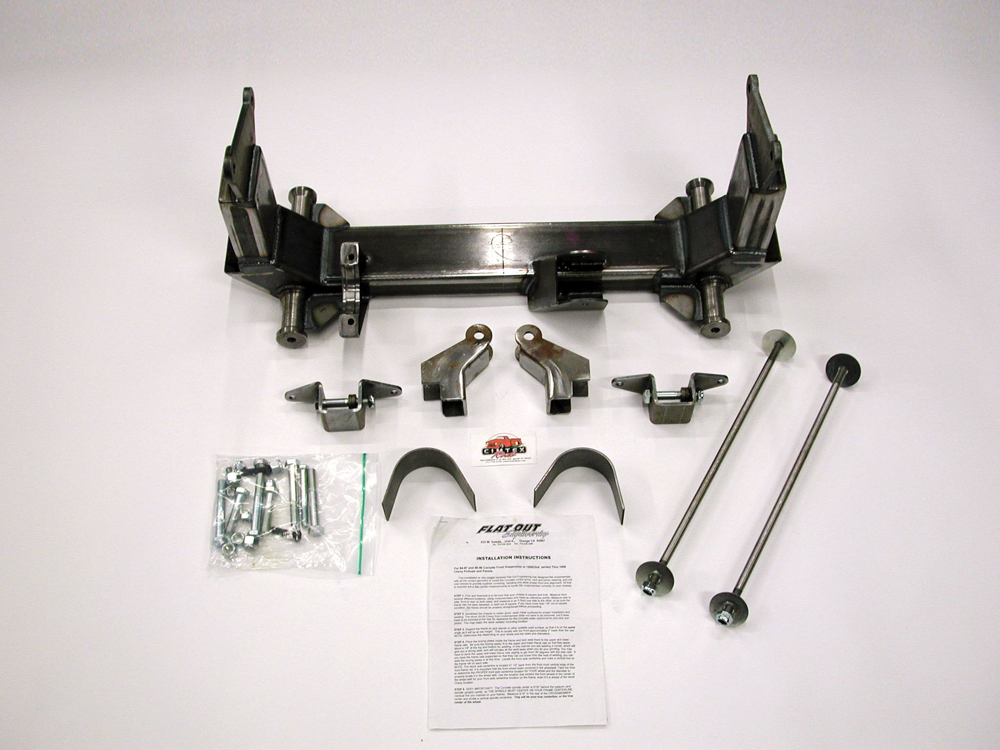
Now, before we get too far ahead of ourselves, we need to discuss the actual Flat Out Engineering ’84-’87 Corvette C4 or ’88-’96 Corvette C5 IFS to ’55-’59 Chevrolet truck front crossmember kit. “Donnie McNeal at Orange, California’s Flat Out Engineering has built a well-designed 2×4-inch, mild steel tubular (box) front crossmember, which will accept an ’84-’87 Corvette C4 or an ’88-’96 Corvette C5 IFS with factory rack-and-pinion steering,” said Darrell. “But rather than use the factory monoleaf Owens Corning fiberglass Corvette front spring, Flat Out Engineering has replaced it with a pair of Aldan Eagle coilover shocks, which are bolted to the C4’s lower control arms on one end and secured to the top of the -framerail via a weld-on bracket on the other.” Flat Out Engineering’s C4/C5 crossmember kit comes with all of the necessary mounting brackets and hardware, a pair of 12-gauge sheet steel boxing plates (measuring approximately 22 inches in length), a set of C4 Corvette rack-and-pinion-steering C-notch plates and a pair of lower control arm mounting shafts, including the necessary mounting bolts, nuts and washers and fully detailed instructions. Of course, what remains is for you to come up with the actual Corvette IFS and Corvette rack-and-pinion, which will add approximately $1,000 to the $795 base price for the kit.
“Any competent chassis builder should be able to install one of these suspension systems within 8-10 hours’ time,” commented Darrell. However, home installers should be advised that certain welding skills are absolutely essential. You will also need to have a variety of specialty tools on hand, such as a welder, perhaps a plasma cutter, a Port-A-Power, a heavy-duty grinder, jackstands, a number of different size levels and angle finders, C-clamps, hammers and an extra helper or two.
Back to the chassis: Once the Cimbanins determined the actual centerline of the Corvette C4 front spindle, they set the ride height of the front of the chassis at 6 inches. As previously mentioned in our introduction, the rear framerails on the ’56 would be kicked up an additional 2 inches in the rear for total of 8 inches, which results in a very nice built-in rake for the ’56. This way, once the Flat Out Engineering front crossmember is permanently installed in the chassis, it not only sets the front control arm angle, but it also sets the built-in caster. With ride height, control arm angle and caster set, the Cimbanins tack welded the chassis to the frame jig to keep it from “walking.” Then they tack-welded in a 1×1-inch box tube front brace between the front frame horns to maintain front rail concentricity.
From there, the two fabricators trial fit the Flat Out Engineering Corvette C4 front crossmember into the chassis. Initial fittings revealed that the ’56’s stamped steel lower framerail is not concentric with the upper rail, so prior to performing any boxing the protruding area on the lower lip of the chassis had to be squared up. A sectional wedge measuring approximately 1 to 1/2 inch and 1-1/4 feet in length was removed from each side of the lower framerails, allowing the boxing plates to be squared up to the chassis. With this material removed, the boxing plates were tack welded into position. Then the Cimbanins trial fit the Flat Out Engineering front crossmember for the second time. In the process, the new front crossmember was leveled and cross referenced to the centering marks from chassis to crossmember. Once determined that it was properly positioned and leveled, it was measured and checked again.
Homebuilders may be interested to know that Flat Out Engineering’s directions mention the fact that the stock stamped-steel GM front crossmember does not have to be removed when installing this kit. Nonetheless, it must be notched at the rear in order to clear the Corvette C4/C5 lower control arm nuts. Since it had to be partially trimmed anyway, Tim and Darrell decided to remove it entirely. After the Cimbanins rechecked their measurements, they fabricated a new forward member out of 2×4-inch box tubing. “This particular item doesn’t come with the kit, but since we intend to run a 1-inch solid front antisway bar, we felt like we needed more rigidity at the front of the chassis, and not only does it look better than the old factory GM front crossmember—it’s also going to give us a place to mount the bar.”
With the new forward member mounted in place, the next order of business was boxing in the entire forward section of the frame. This, too, is optional, as the Cimbanins felt that the chassis would not only be stronger, but it would also be cleaner looking. Remember that this truck is going to be extensively shown. In the process, all superficial mounting holes in the chassis were welded up and ground smooth.
Once master welder/fabricator Billy Walker created and installed the boxing plates, Tim and Darrell again took their measurements. “You can’t measure enough when it comes to these things. Measure, measure and measure some more!” The Cimbanins used a floor jack and level to final install the new Flat Out Engineering Corvette C4/C5 crossmember. Measurements were drawn from all points on the chassis, and they were checked and rechecked. With the new Flat Out Engineering/Corvette crossmember completely level, it was tack welded into place. “Due to the fact that things tend to expand and shift around during the welding process, we rechecked our measurements as we went to be sure that everything was in its place. Once we were satisfied with the fit, both the Flat Out Engineering Corvette crossmember and our new forward crossmember were both final welded in place,” said Darrell.
With the new Corvette IFS crossmember final welded in, the next step was to figure out where the tie rods from the C4 Corvette rack-and-pinion steering assembly were going to intersect with the bottom of the Chevrolet pickup’s framerail. All that was required was bolting the steering rack into the cradle on the Flat Out Engineering crossmember using the factory Corvette bolts and hand turning the unit lock to lock. Once the Cimbanins made note of the offending areas, they used the actual C-notch plates provided in the Flat Out Engineering kit as templates. Cutting of the actual chassis requires the use of something precise, such as a plasma cutter, since you’re going to be cutting through double-wall-thickness material. Remember, the front framerails of the ’56 chassis are now boxed in. Trial fitting of the C-notch plates while checking for proper clearance will obviously take a little time, and some grinding may be necessary in the process. Once satisfied with the fit, the C-notch brackets themselves can be final welded in place, and the Corvette steering rack can be permanently bolted to the Flat Out Engineering front crossmember using the 3/8×3-inch crossmember mounting bolts (provided in the kit, along with the two 8mm Corvette rack bolts and the factory mounting clamp).
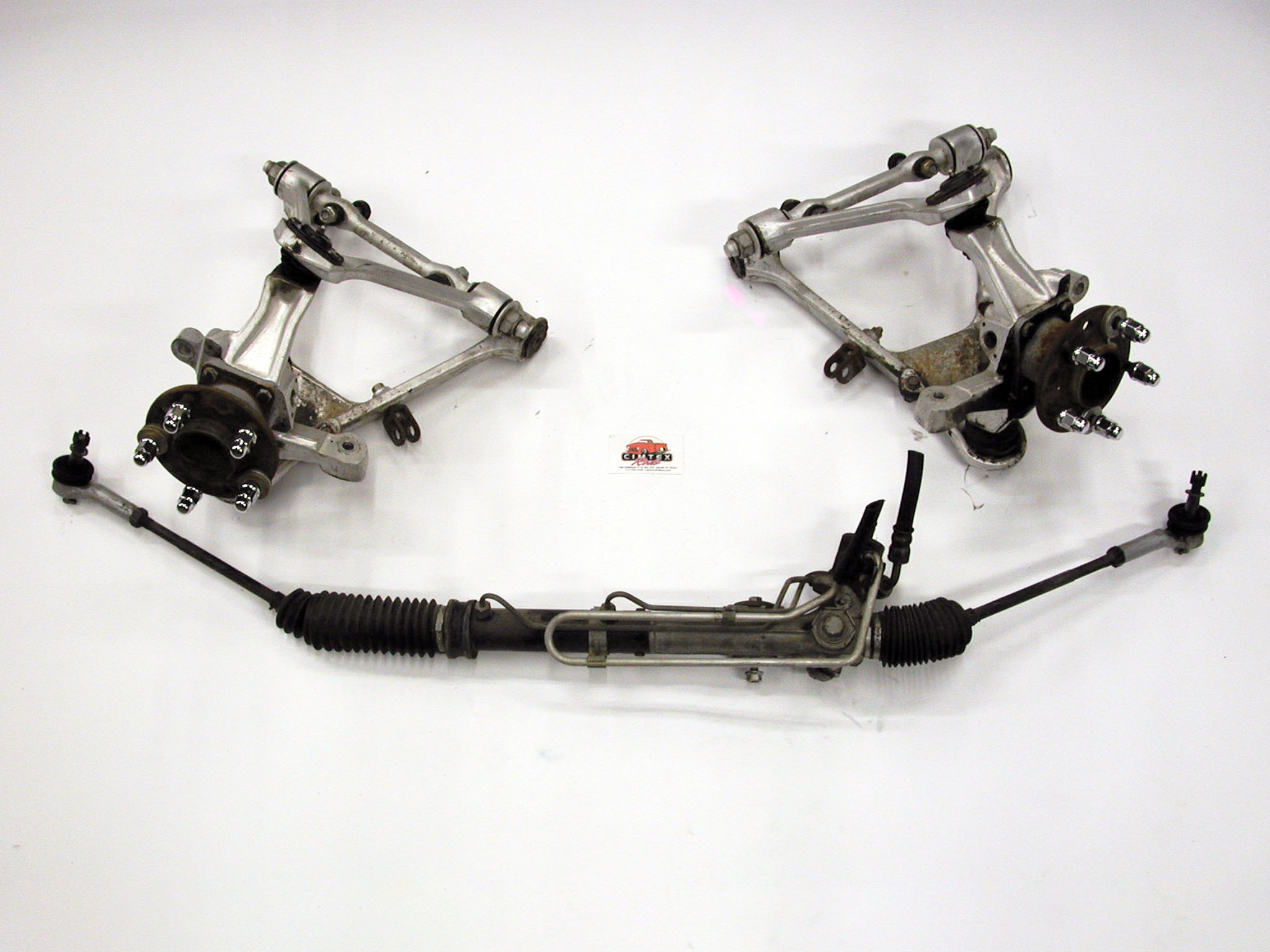
Of course, this is followed by the actual installation of the Corvette C4 suspension, starting with the lower control arms. Flat Out Engineering furnishes a pair of specially machined, 1/2×24-inch-long threaded shafts that mount the lower Corvette control arms to the new crossmember using the provided 12mm nuts and washers. At this juncture, it might be advisable to replace the actual control arm bushings. In this instance, when final assembly comes around, the plan is to install a set of Energy Suspension Hyper-Flex polyurethane upper and lower control arm bushings, along with show polishing the control arms -themselves.
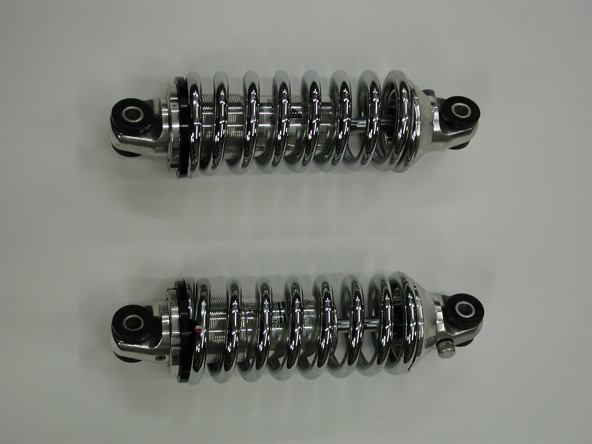
The next step in the installation is bolting up the Aldan Eagle coilover shocks. These shocks measure 12-1/2 inches in length, and there is a right and a left side, so it’s important not to mix them up. Using the lower shock mounting brackets provided in the Flat Out Engineering kit, the Cimbanins first installed the bracket to the bottom of the Aldan Eagle coilover shock, and then it was bolted to the bottom of the actual C4 control arm using the provided 3/8-inch buttonhead bolts. With that done, the next order of business is the installation of the upper control arms to the mounting tab located at the top of the Flat Out Engineering C4 front crossmember using the 12mm Corvette metric bolts, and all the necessary shims which came with the Corvette C4/C5 suspension. Note: Be sure to use all the factory shims in order to maintain proper suspension geometry and alignment! After bolting together both sides, all that remains is locating proper placement of the coilover shock top mounting brackets onto the classic tri-5 Chevrolet upper framerails. Proper shock bracket alignment is achieved by locating the centerline of the upper shock bracket dead center to the new crossmember, at the top of the upper control arm tower butted directly up to the control arm mounting plate itself.
“The beauty of this system is the fact that you can also use the stock Corvette vented rotor/dual-piston disc brakes,” says Darrell. Many of you may wish to use one of the great aftermarket Corvette C4/C5 disc brake upgrade kits for this application, such as those from Baer Racing or Wilwood Engineering.
When aligning the new C4 suspension, the stock factory Corvette alignment specs will be used; that is, once the weight of the LT5 engine used in the ZR1 Corvette and all of its related components are bolted into the chassis.
So there you have it: Cimtex Rods’ modified 1956 Chevrolet pickup truck chassis is now complete with a Flat Out Engineering Corvette C4 front crossmember, Corvette C4 rack-and-pinion-steering and Aldan Eagle coilover shock-equipped Corvette C4 independent front suspension. In Part III, we’ll be covering the modification of the rear framerails, along with the installation of a 1986 Corvette C4 independent rear suspension. Stay tuned!
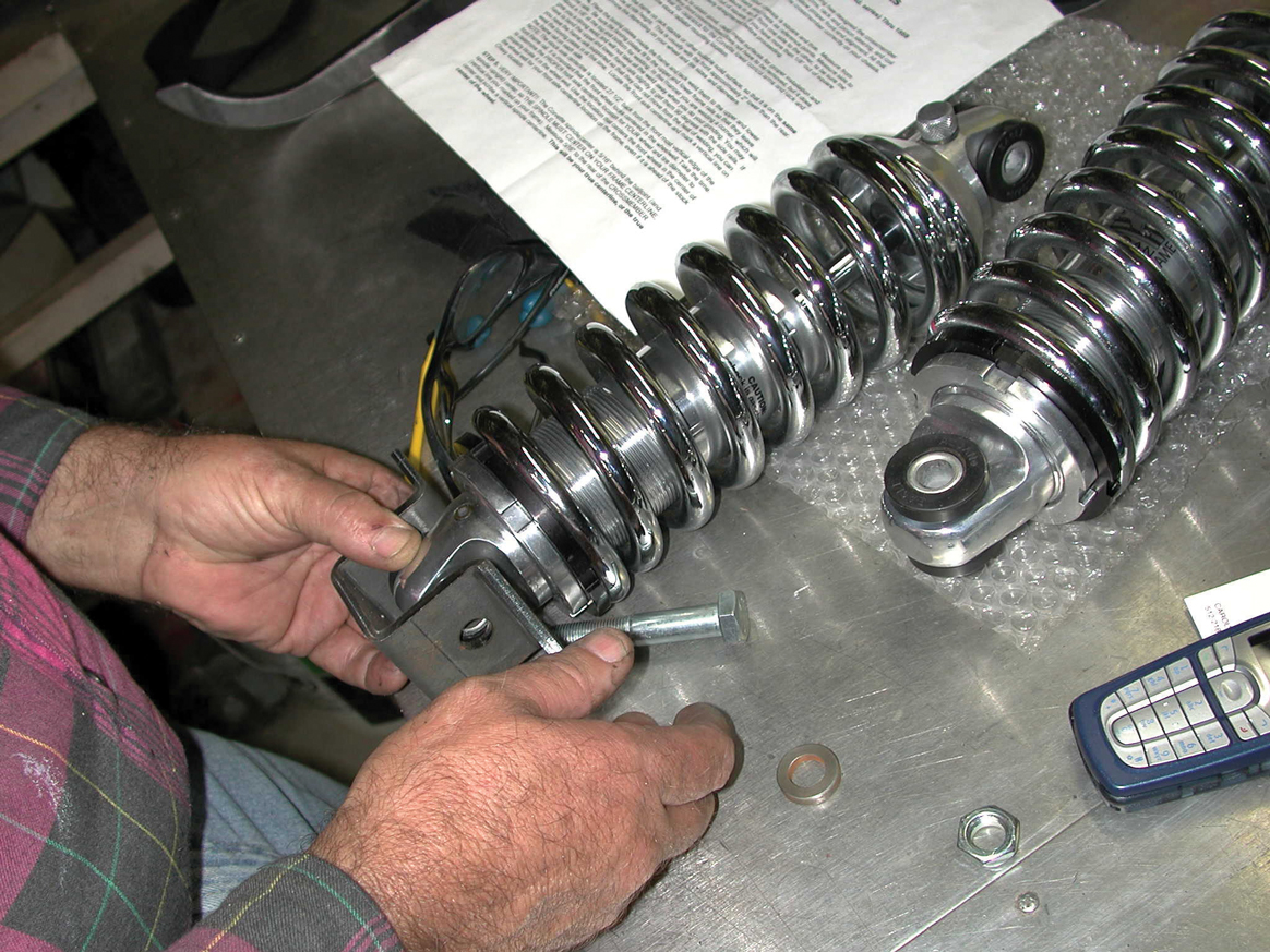
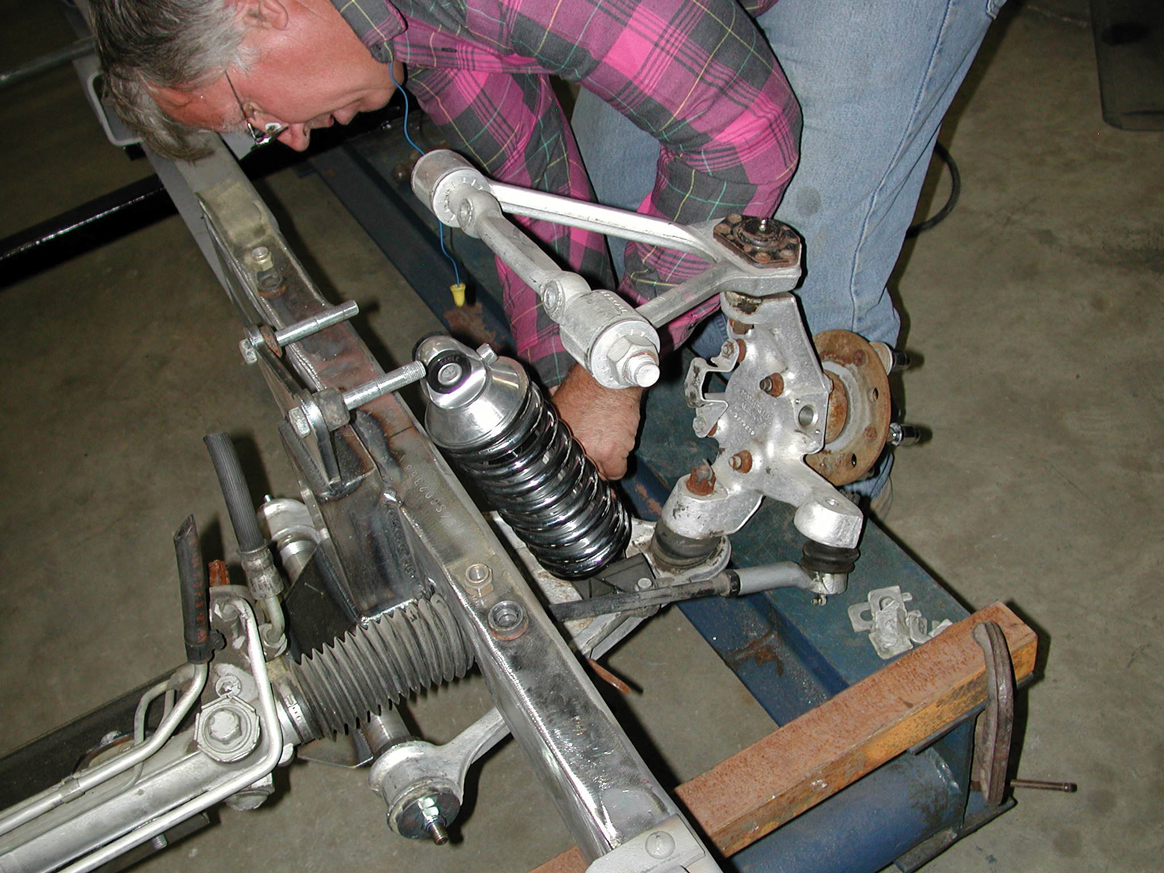
3. This application also calls for a pair of coilover front shock absorbers to replace the Owens Corning fiberglass GM monoleaf spring. Our builders opted for a pair of Aldan Eagle coilover shocks measuring 12-1/2 inches in length.
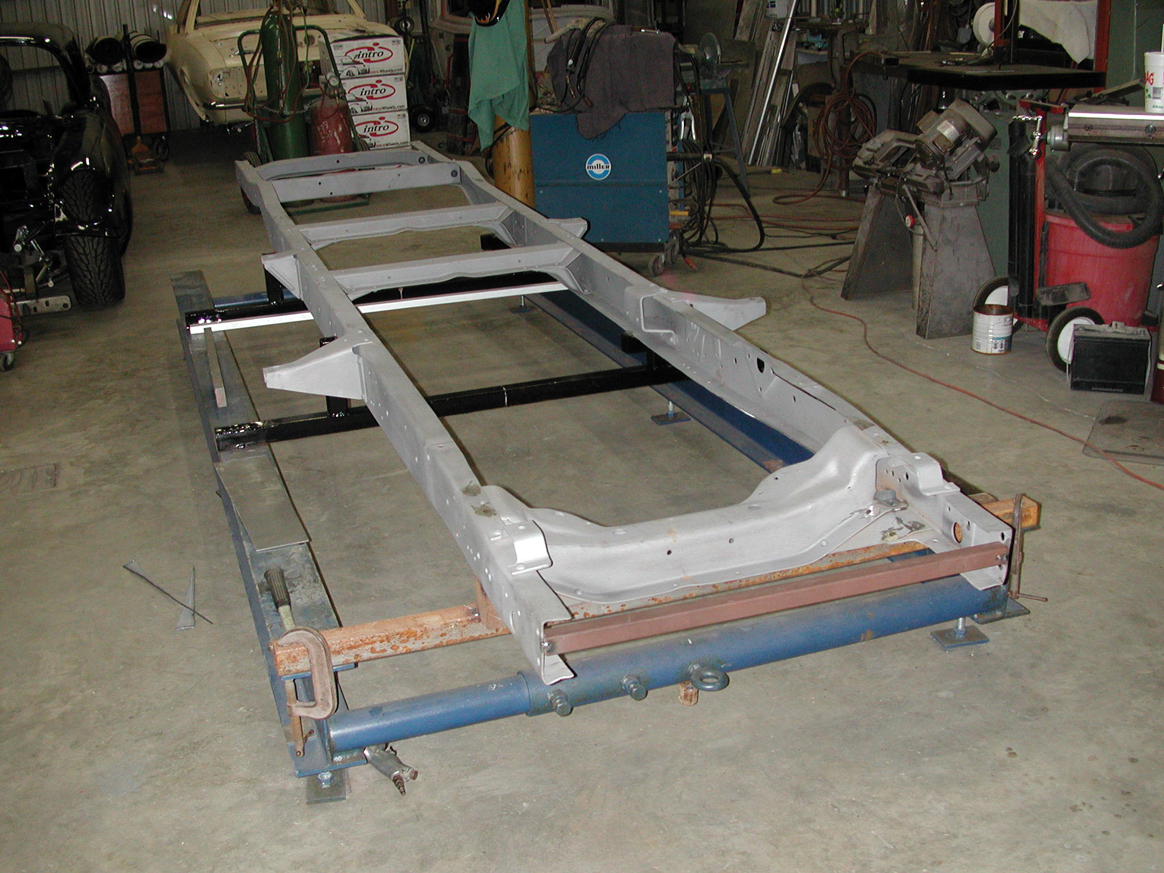
4. After returning from the sandblaster, Tim and Darrell installed their soon-to-be-modified ’56 1/2-ton chassis on the shop’s chassis jig, and they began squaring it up.
5. All measurements are carefully checked, including side to side at the front of the ’56’s frame horns. It was discovered that the driver’s-side front frame horn had been slighty tweaked and required minor straightening.
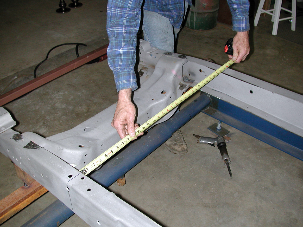
6-7. The centerline of the factory tri-5 front axle is also checked, and a measurement of 27-1/2 inches is arrived at and clearly marked.
6-7. The centerline of the factory tri-5 front axle is also checked, and a measurement of 27-1/2 inches is arrived at and clearly marked.
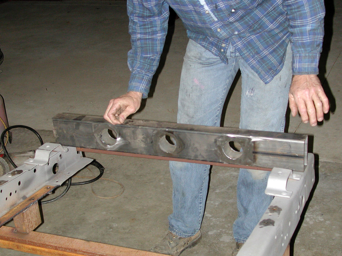
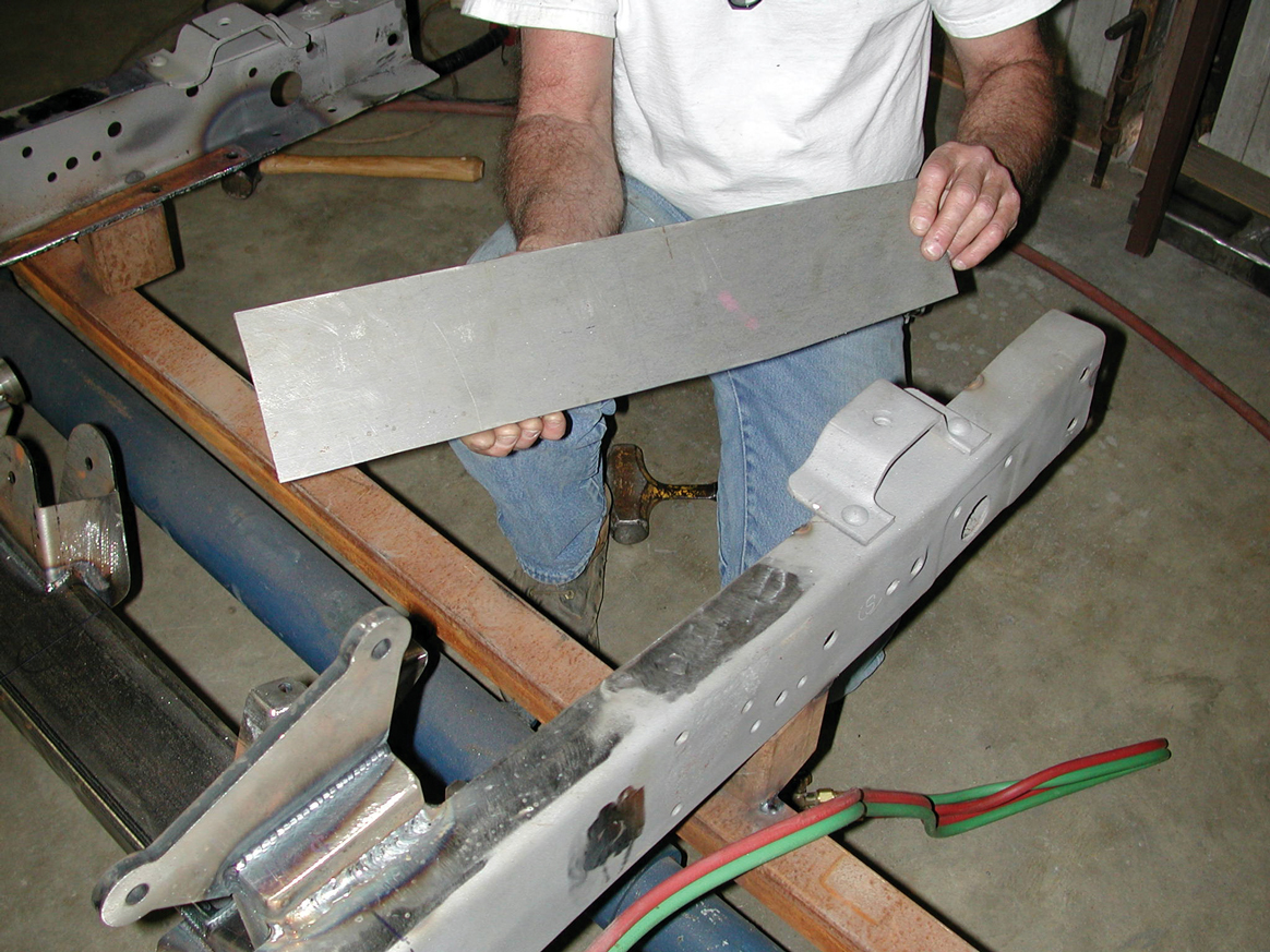
8. Prior to installing the 22-inch-long 12-gauge sheer steel boxing plates, the lower framerails on the ’56 had to be squared up. A wedge measuring 1-1/4x1/2x12 inches was removed.
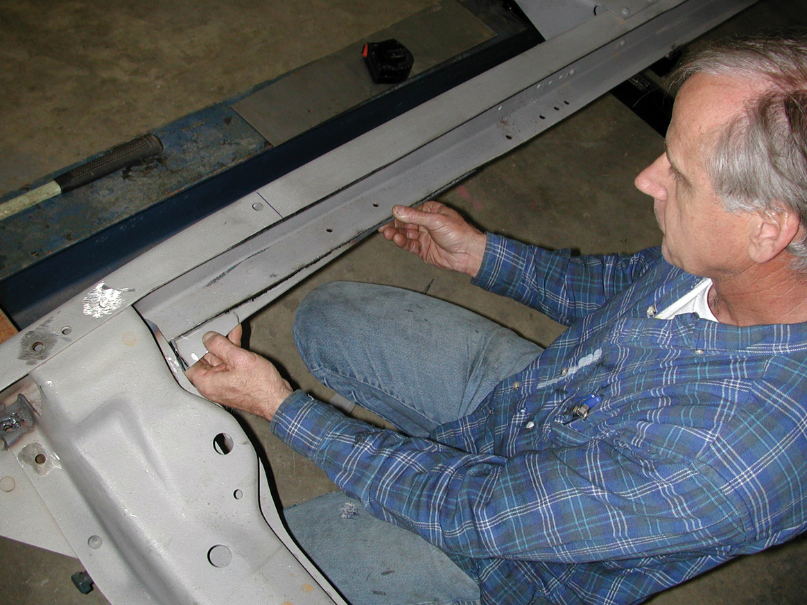
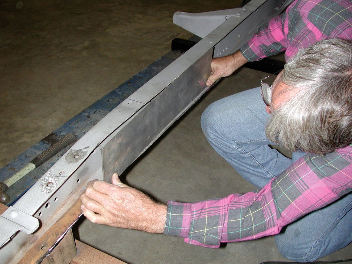
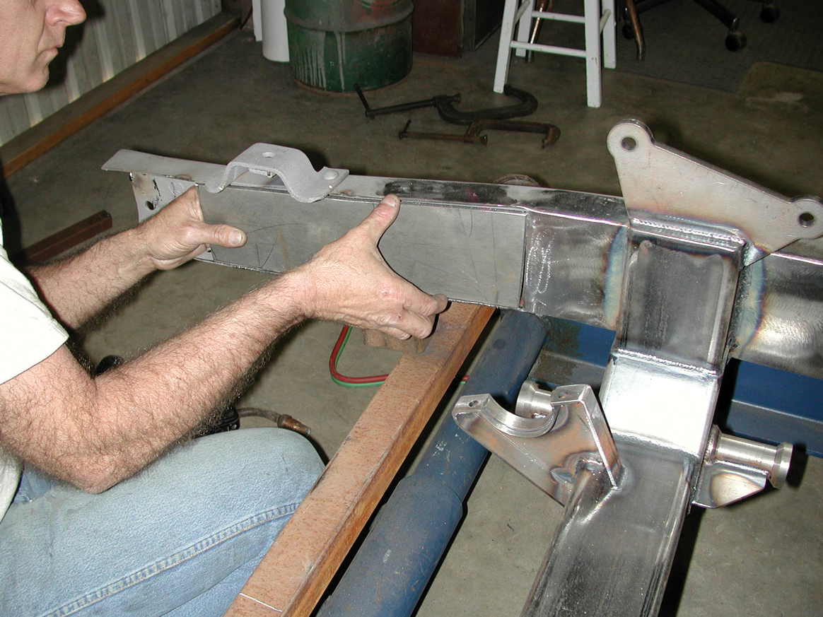
9. Darrell Cimbanin trial fits the passenger’s-side Flat Out Engineering box plate to the inside of the tri-5 Chevrolet chassis.
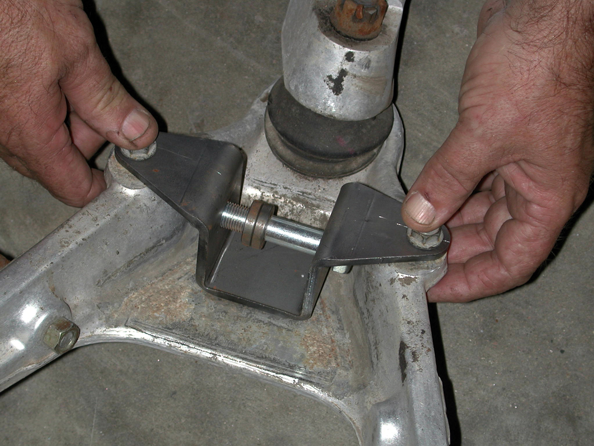
10. In order to maintain front framerail concentricity, the Cimbanins tack-welded in a 1x1-inch square piece of tubing to keep the front rails from “walking.”
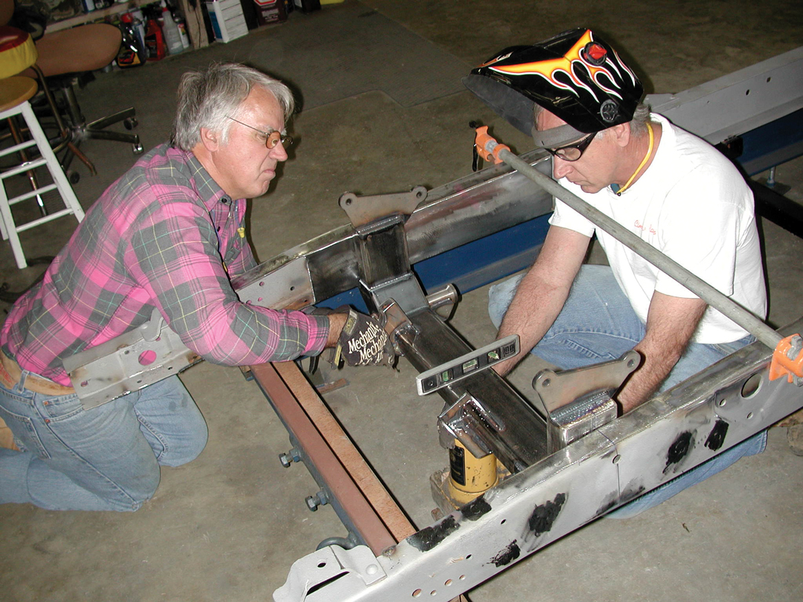
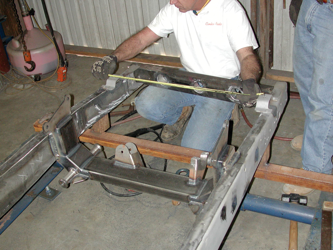
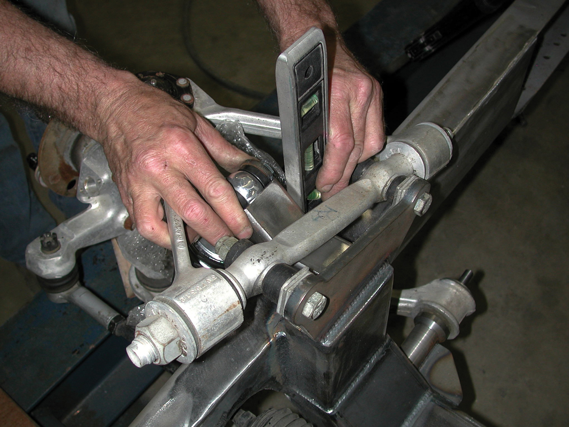
11. Once again, measurements were taken to ensure that everything was totally square, and they were double checked again and again.
12. With the Flat Out Engineering tubular front crossmember initially installed, Tim Cimbanin points to the area on the OE front crossmember that needed to be trimmed to accommodate the Corvette C4 lower control arm bolts.
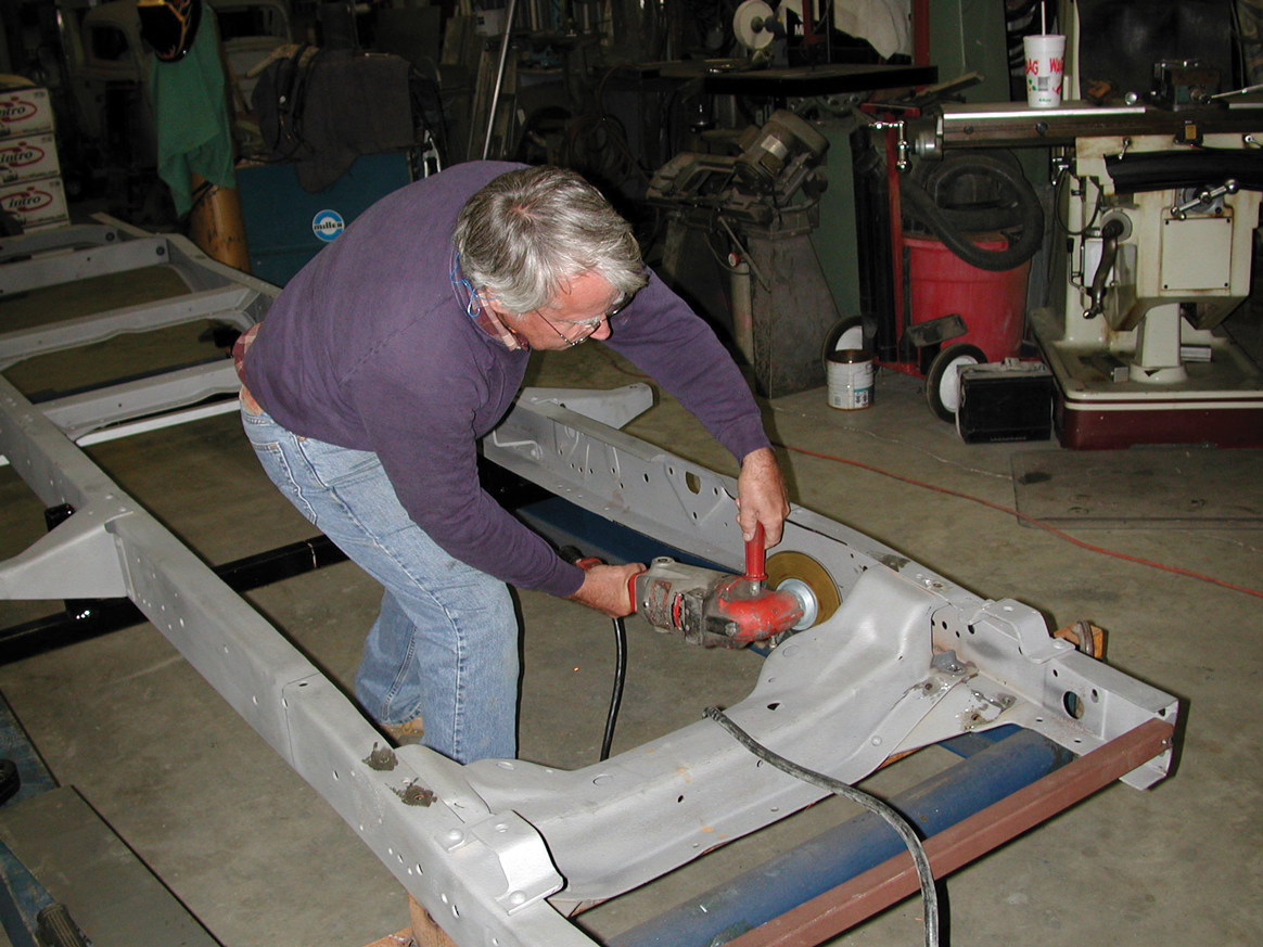
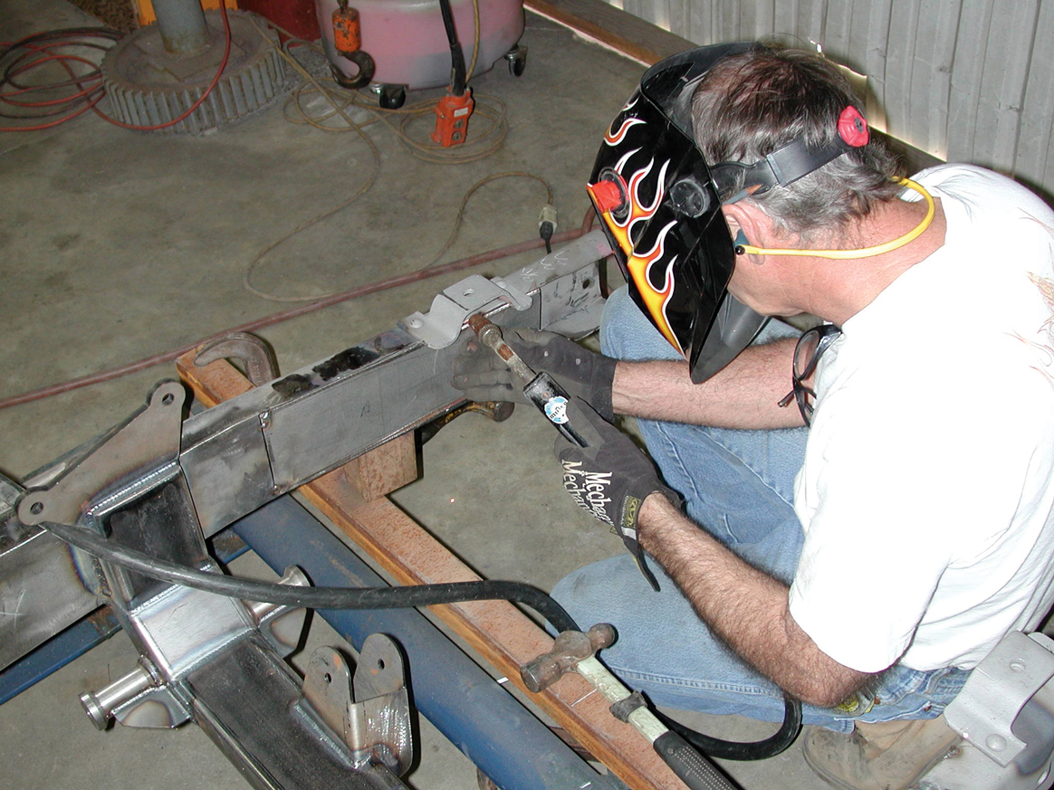
13. Rather than leave the OE front crossmember in place, the Cimbanins elected to remove it entirely. Here Billy Walker gets the job done in short order.
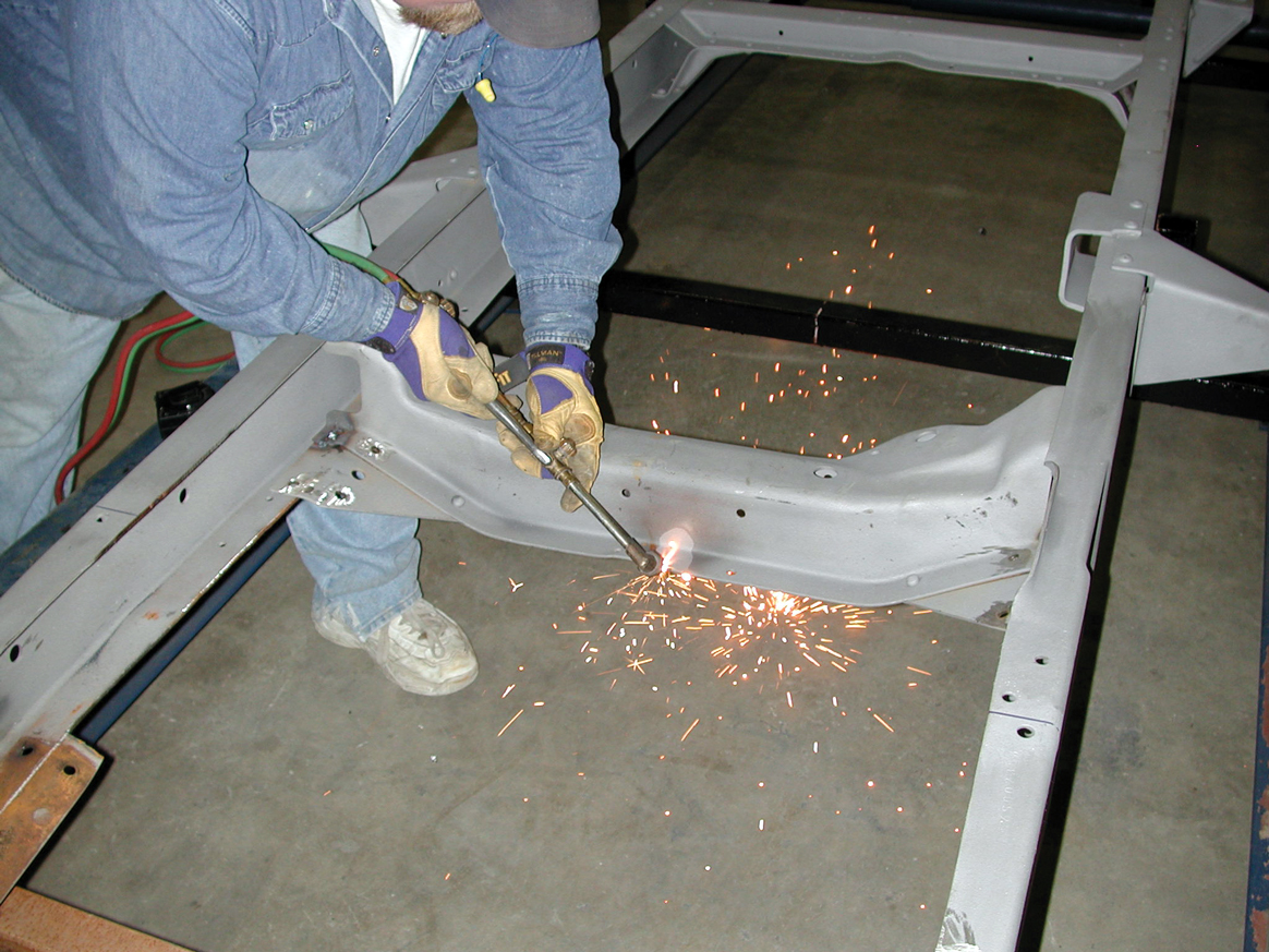
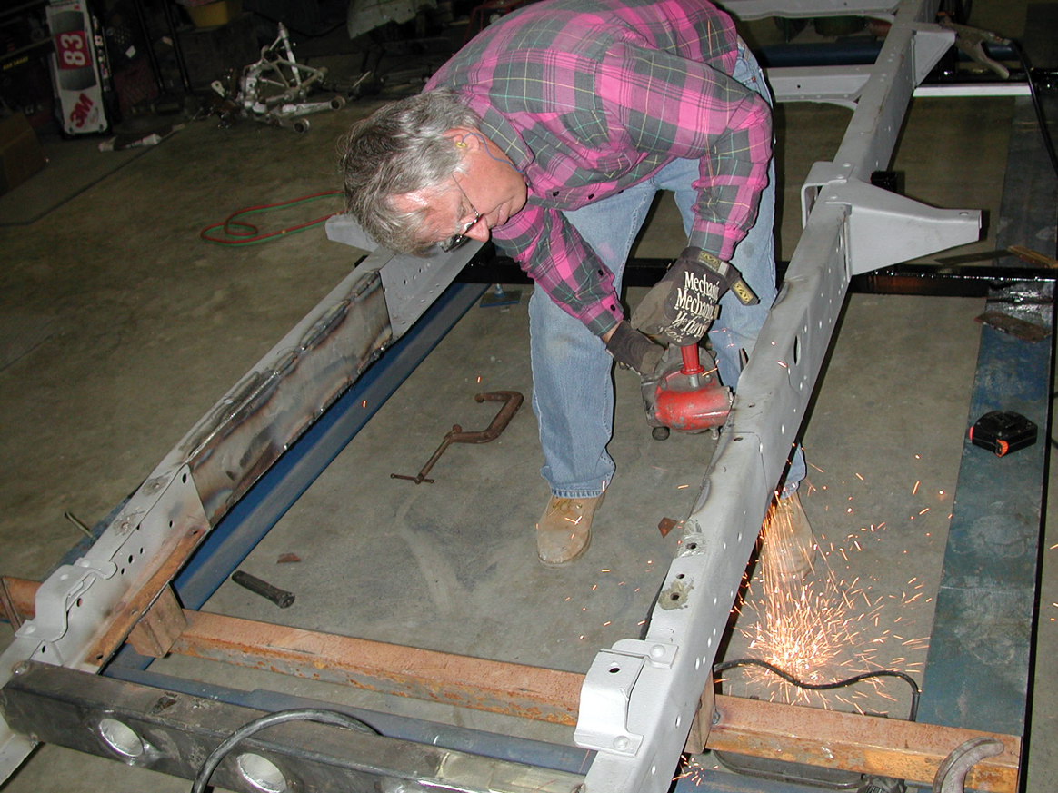
14. Next Darrell uses his Craftsman plasma cutter to trim away the factory lower crossmember mounting lips on both sides of the chassis. This area is then ground smooth.
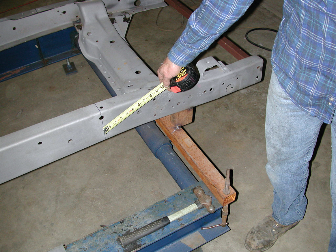
15. The Cimbanins then trial fit the new 2x4-inch box tube forward member that they fabricated for the chassis. This piece is located 5-1/2 inches to the rear of the front frame horns and will be used to attach the front antisway bar.
16-17. Tack welding the Flat Out Engineering boxing plates in position came next.
16-17. Tack welding the Flat Out Engineering boxing plates in position came next.
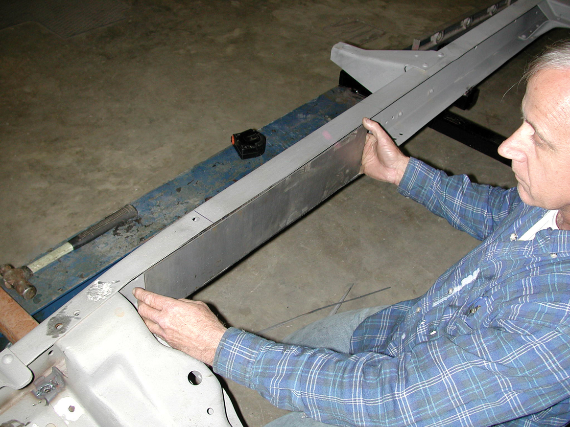
18. With the boxing plates tack welded into position, Tim thoroughly cleaned off all the welding slag prior to refitting the Flat Out Engineering tubular front crossmember, setting it in place.
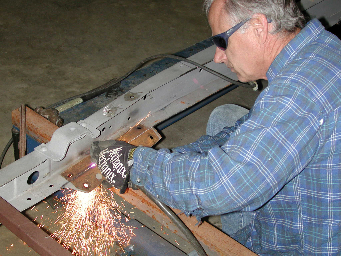
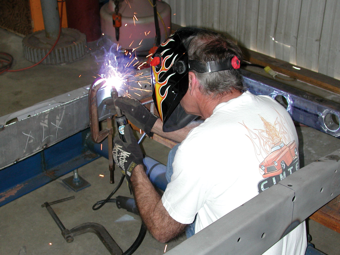
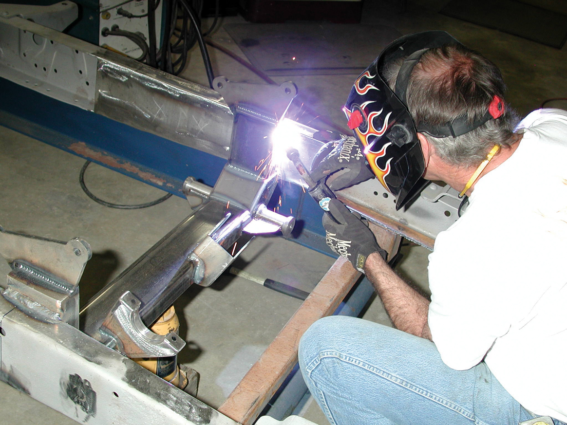
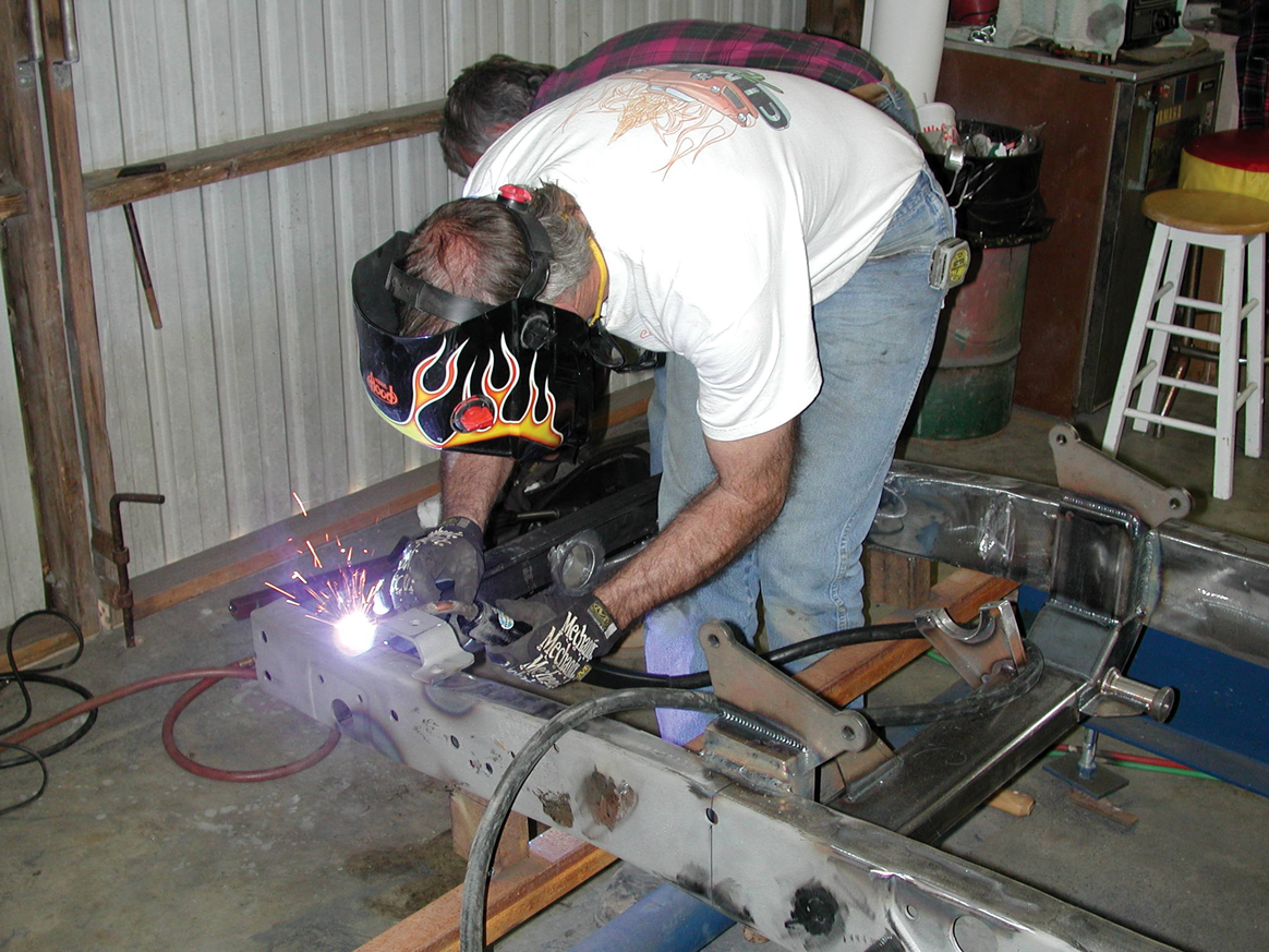
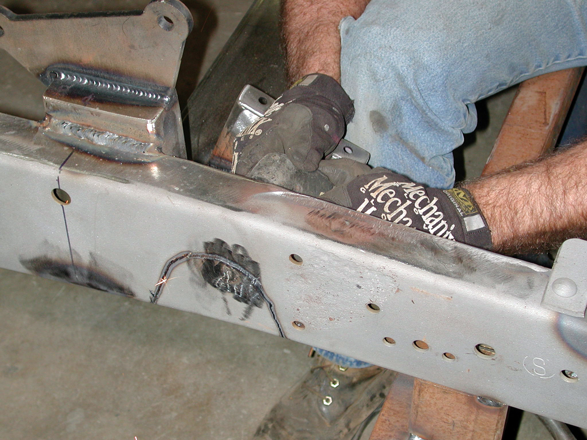
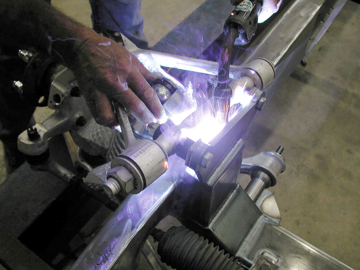
19-20. At this juncture, it was necessary to heat and reshape the lip of the driver’s-side framerail, where the Pitman arm used to clear the ’56 framerail. Once heated up, Tim uses a small sledgehammer to pound the lip flat, and then Darrell final welded it flush to the box plate.
19-20. At this juncture, it was necessary to heat and reshape the lip of the driver’s-side framerail, where the Pitman arm used to clear the ’56 framerail. Once heated up, Tim uses a small sledgehammer to pound the lip flat, and then Darrell final welded it flush to the box plate.
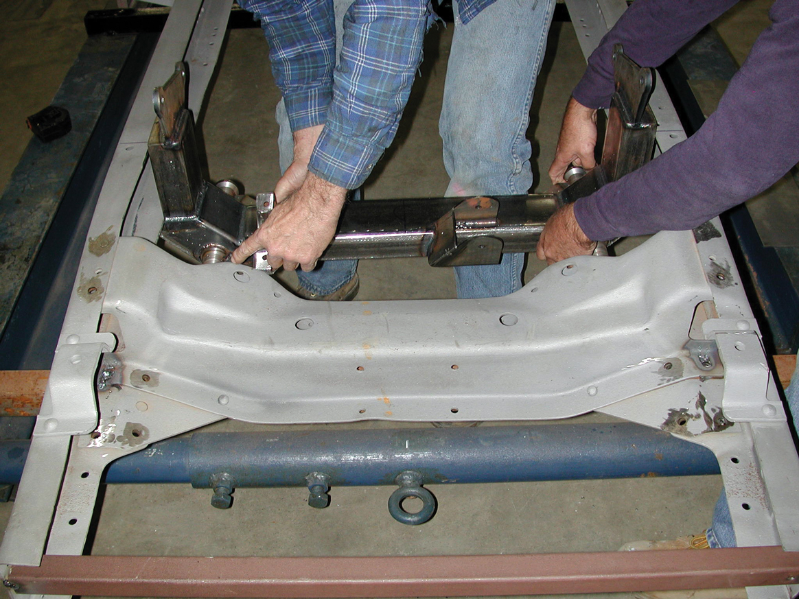
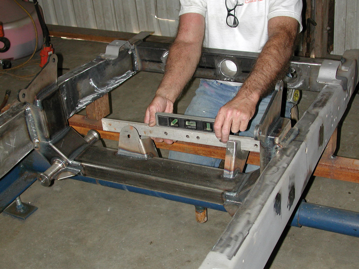
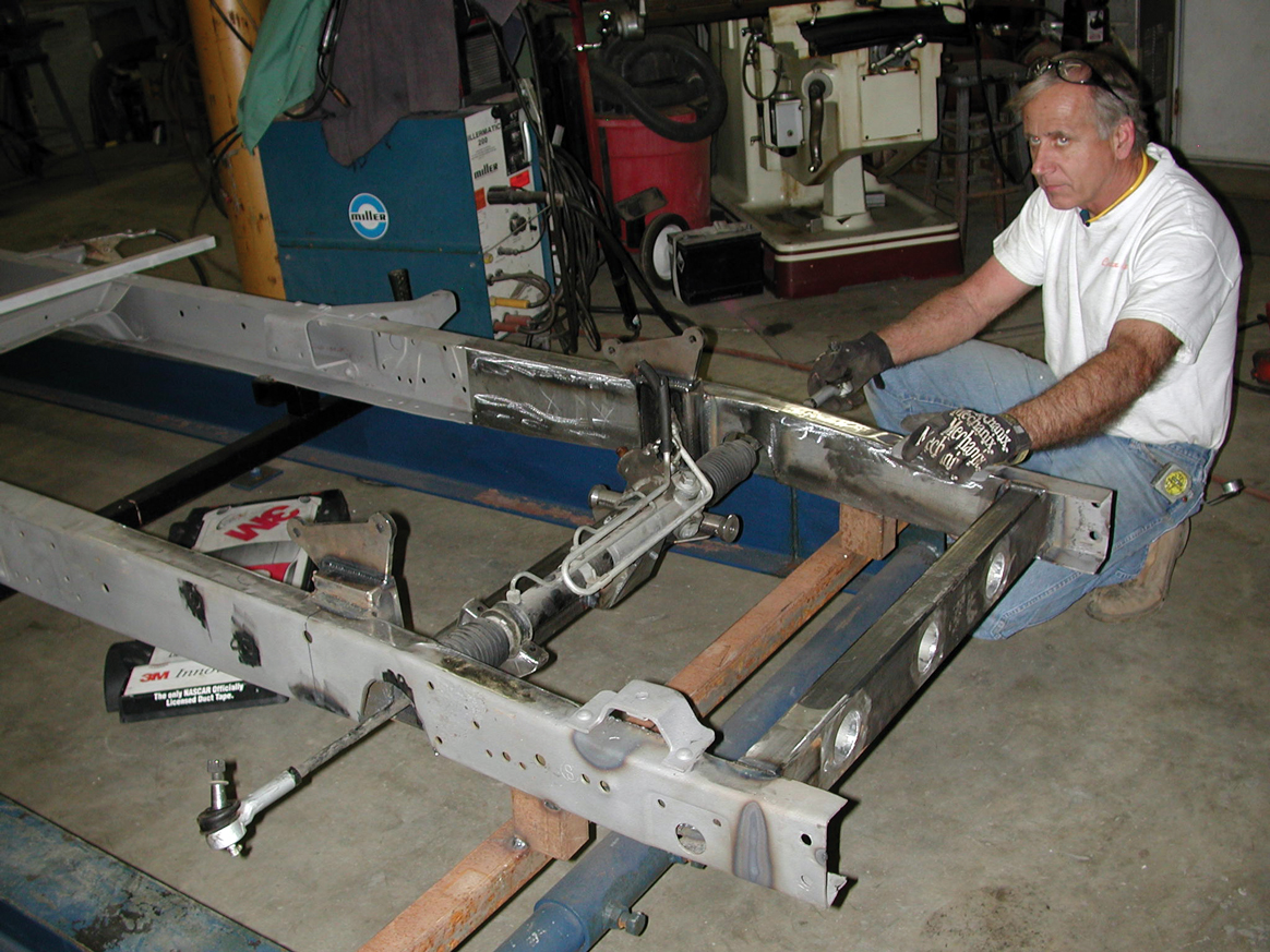
21. Team Cimtex installed the Flat Out Engineering front crossmember for the final fitting, using a floor jack and levels to make sure that everything fit where it’s supposed to.
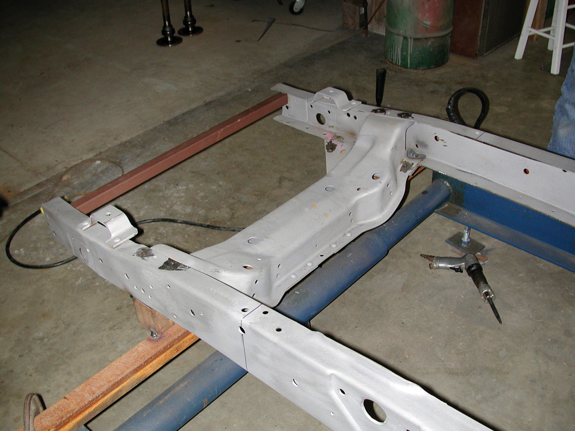
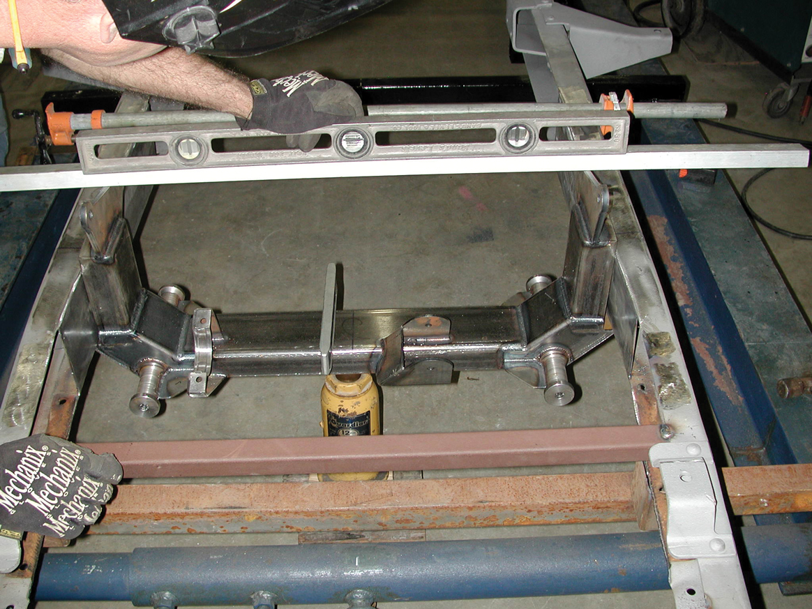
22. Note that the true centerline on the Flat Out Corvette C4 crossmember matches perfectly to the centerline on the ’56 chassis.
23-24. Everything was totally squared up, and then the Flat Out Engineering Corvette C4 front crossmember was tack welded in position between the ’56’s modified front framerails.
23-24. Everything was totally squared up, and then the Flat Out Engineering Corvette C4 front crossmember was tack welded in position between the ’56’s modified front framerails.
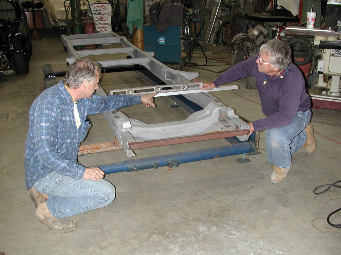
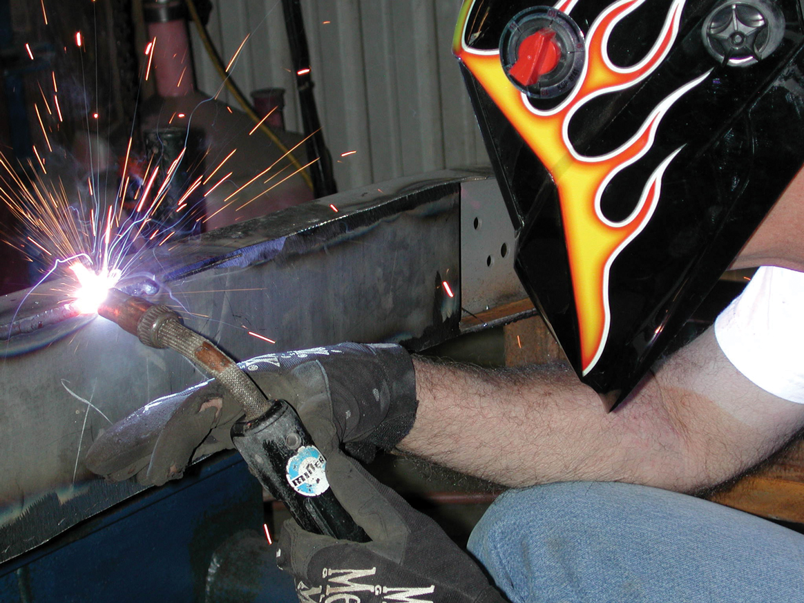
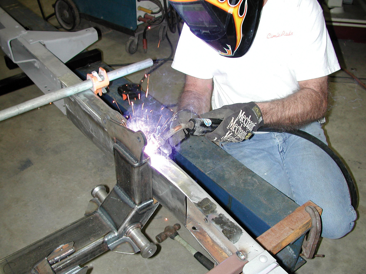
25-26. Prior to final welding, the Cimbanins rechecked their measurements. Now it’s time to break out the welder.
25-26. Prior to final welding, the Cimbanins rechecked their measurements. Now it’s time to break out the welder.
27-28. At this point, Team Cimtex fabricated a set of forward rail boxing plates, which are not part of the Flat Out Engineering kit.
27-28. At this point, Team Cimtex fabricated a set of forward rail boxing plates, which are not part of the Flat Out Engineering kit.
29. These plates were trail fit to the chassis and then tack welded in place.
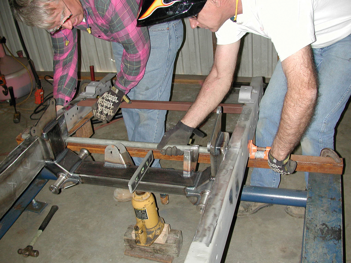
30-31. Now it’s time to final weld the forward crossmember in place. All measurements were once again double checked.
30-31. Now it’s time to final weld the forward crossmember in place. All measurements were once again double checked.
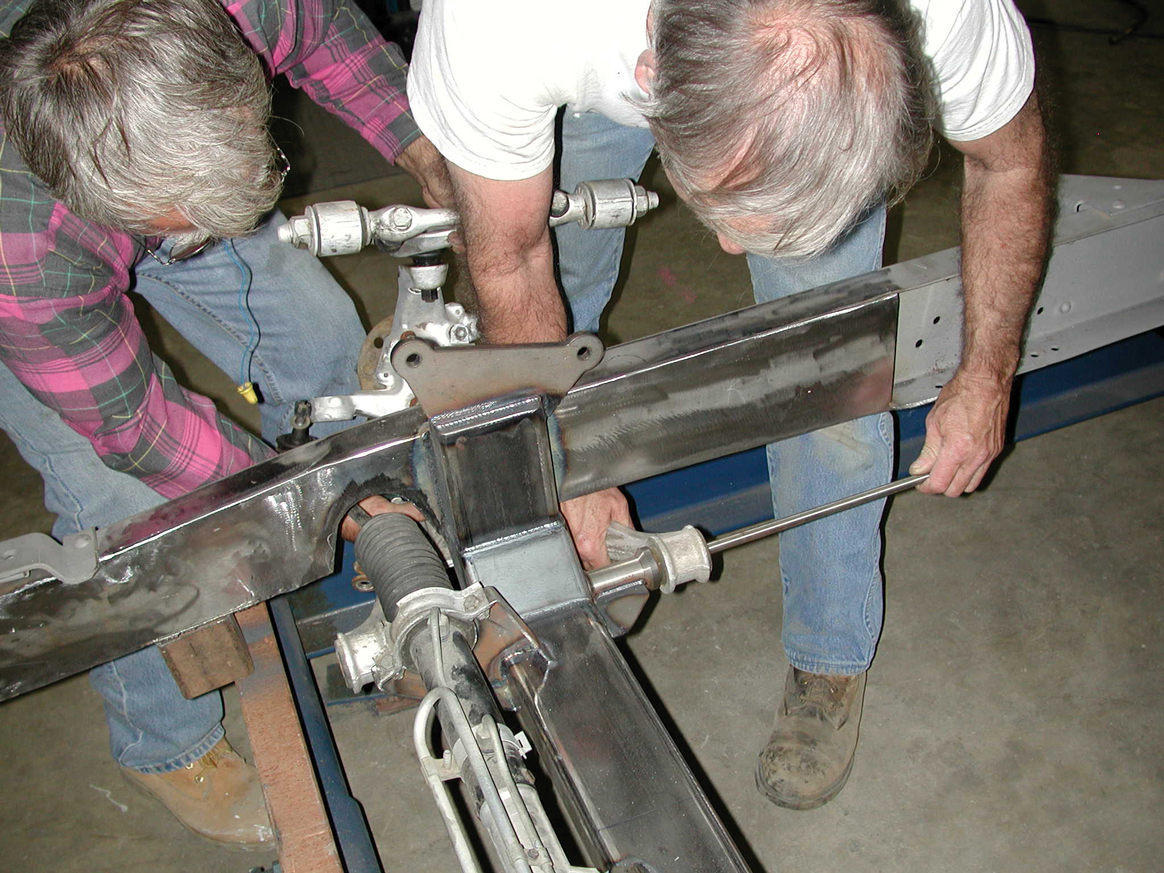
32. Next the centerline of the Corvette C4 steering rack was checked prior to C-notching the tri-5’s front frame horns.
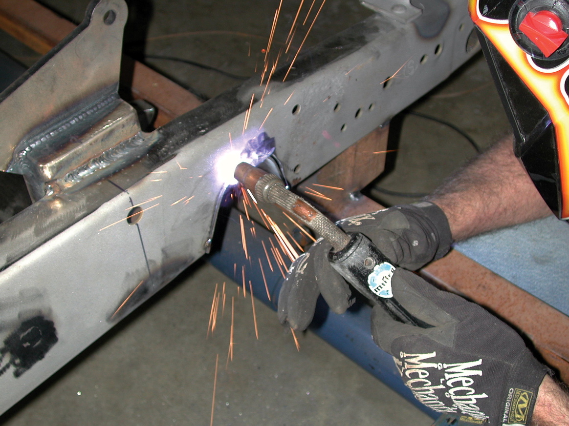
33-34. Darrell used the pre-bent Flat Out Engineering C-notch brackets to arrive at the proper mounting location on the chassis. Then this area was marked, and a Craftsman plasma cutter was used to cut out the ’56’s double-wall-thickness framerails.
33-34. Darrell used the pre-bent Flat Out Engineering C-notch brackets to arrive at the proper mounting location on the chassis. Then this area was marked, and a Craftsman plasma cutter was used to cut out the ’56’s double-wall-thickness framerails.
35. Trial fitting the Corvette C4 rack comes next. It was run lock to lock to ascertain whether there was enough clearance. At this juncture, any modifications that need to be done can still be made.
36. Satisfied with the fit, Darrell tacked up and final welded the Flat Out Engineering C-notch plates to the ’56’s front framerails.
37. In went the Corvette C4 steering rack, and things worked just fine.
38. Now it was time to start bolting together the front suspension. Darrell began by bolting the Flat Out Engineering lower coilover shock bracket to the C4 lower control arms using the provided 3/8-inch buttonhead bolts.
39. Darrell then bolted the upper shock bracket to the top of the Aldan Eagle coilover shock. This bracket will be centered with the centerline of the Flat Out crossmember and welded to the top rail of the ’56 chassis.
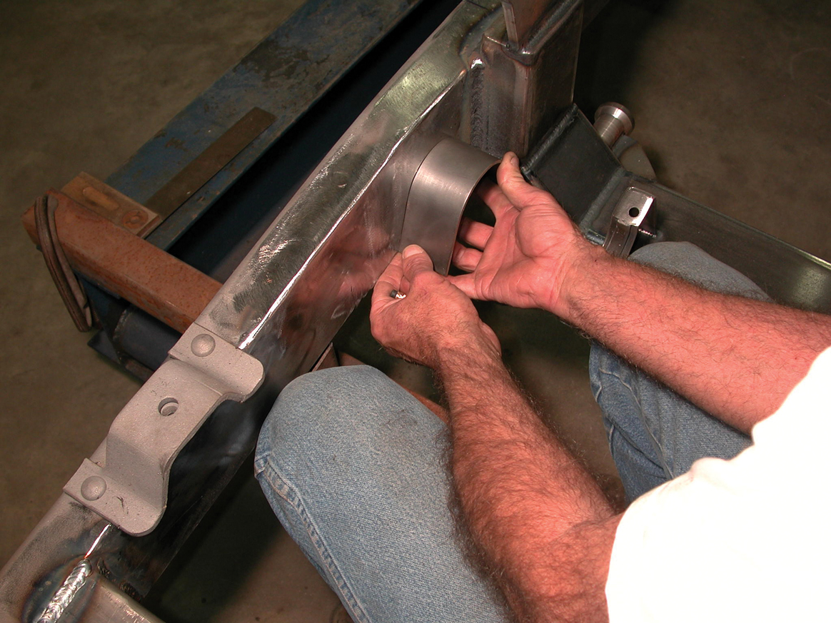
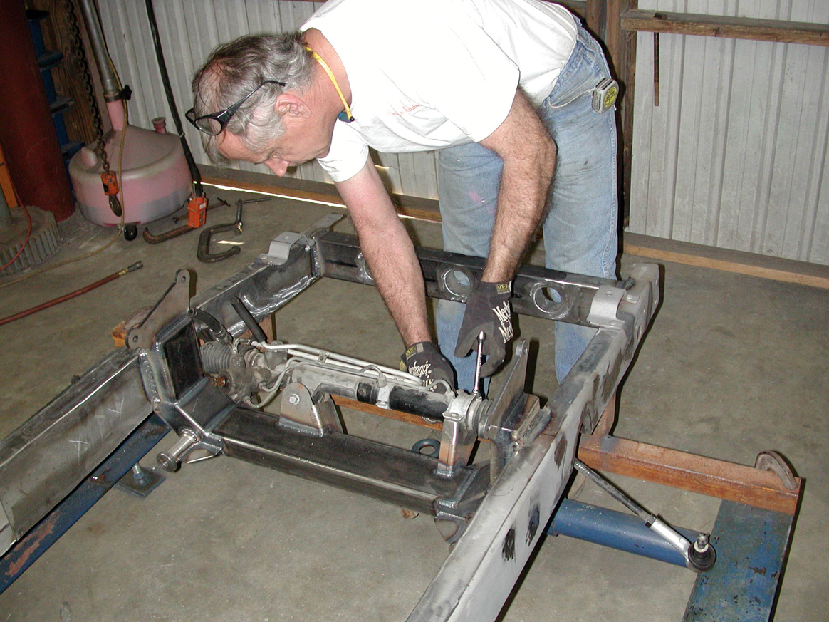
40. With the lower C4 control arm and Corvette front spindle assembly in place, Darrell installed one of the provided 1/2x20-inch-long stainless steel threaded shafts, which secure the lower control arm assembly in place.
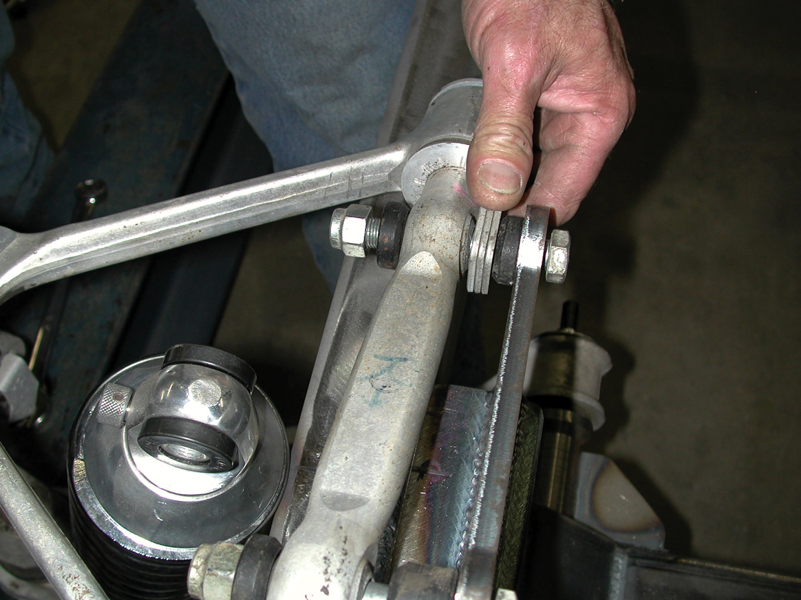
41. Here we see our installer bolting up the upper control arm bracket to the Flat Out Engineering passenger’s side, using the OE 12mm bolts and factory shims. Note: Use all of the accompanying shims, and use them in sequence, or you will have trouble properly aligning (using the factory settings) the front suspension!
42. Next Tim tackled the driver’s side of the modified tri-5 truck chassis.
43-44. With the Corvette C4 front suspension bolted in place, Darrell arrived at the true centerline for mounting the upper coilover shock bracket to the top framerail of the chassis. Once he was satisfied, it was final welded in position.
43-44. With the Corvette C4 front suspension bolted in place, Darrell arrived at the true centerline for mounting the upper coilover shock bracket to the top framerail of the chassis. Once he was satisfied, it was final welded in position.
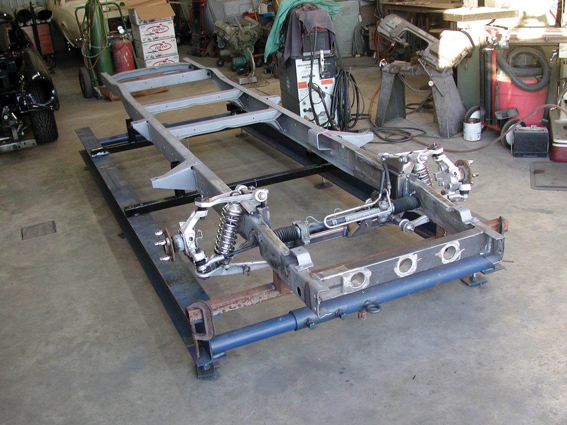
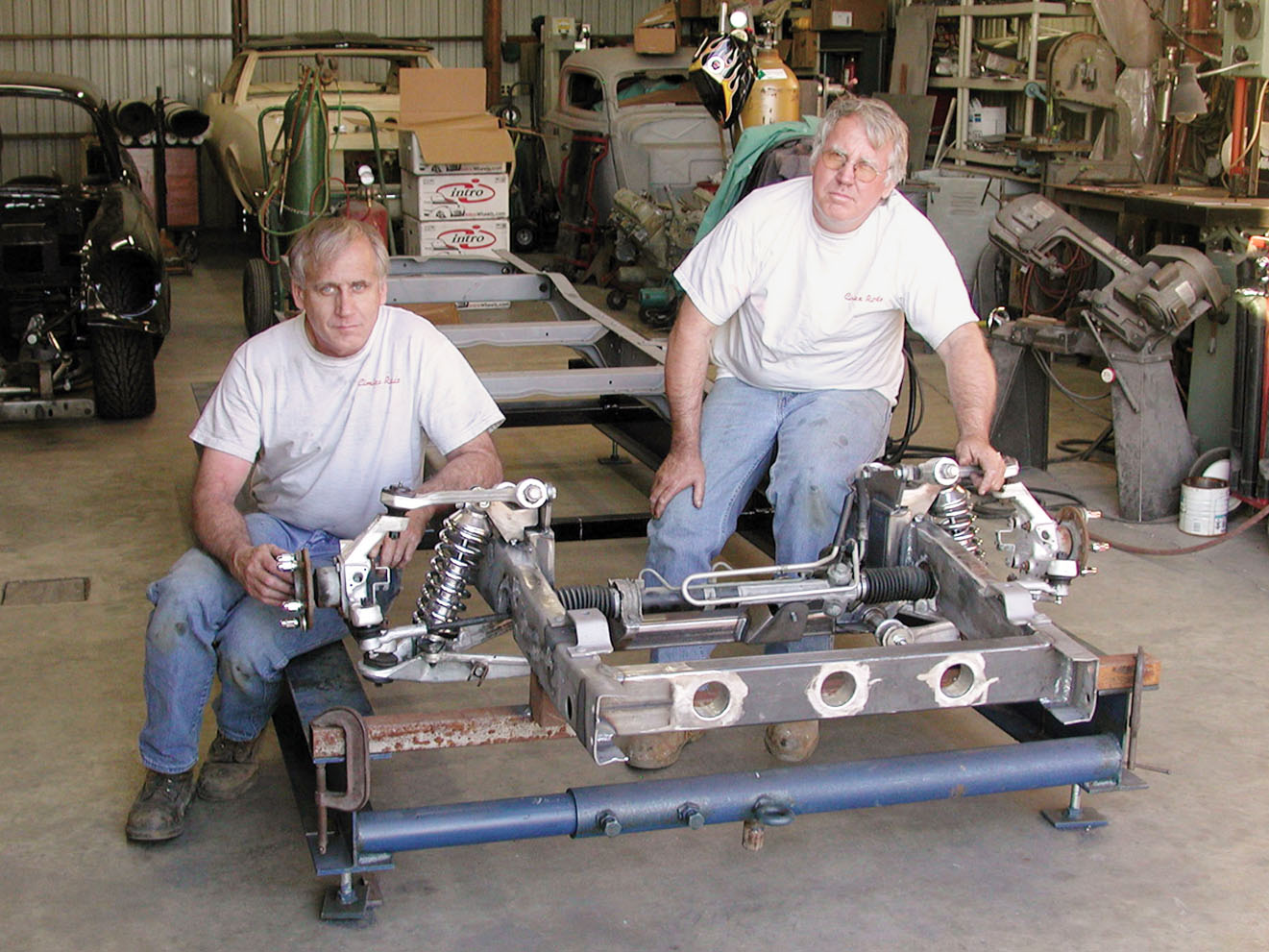
45-46. Here it is: the completed Corvette C4 independent front suspension in a ’56 Chevy 1/2-ton chassis. Once finished, this truck will handle like a dream on rails, which will be a tremendous improvement over stock.
45-46. Here it is: the completed Corvette C4 independent front suspension in a ’56 Chevy 1/2-ton chassis. Once finished, this truck will handle like a dream on rails, which will be a tremendous improvement over stock.
ARTICLE SOURCES
Aldan Shock Absorber Co.
22015 S. Avalon Blvd.
Carson, CA 90745
310/834-7478
Cimtex Rods
P.O. Box 205
Jarrell, TX 76537
512/746-2707
Energy Suspension
1131 Callejon
San Clemente, CA 92673
949/361-3935
