


PACKED WITH POTENTIAL
The Power Programmer is designed so that once the parameters are established and loaded, the unit is pulled and the program remains in the onboard computer until you elect to remove it. The HyperPAC is different; this unit stays in place. In addition to the three stages of performance tuning—the HyperPAC has all of the performance programming benefits of the Power Programmer—it also has diagnostics; an engine monitor with a complete gauge display; a dynamometer, which includes such items such as a horsepower graph; and our favorite, a dragstrip program. This program actually monitors real-time engine operating conditions, has a Christmas tree start, displays a timeslip and will provide you with “magazine-type road test” acceleration times in 10-mile increments. It will record and display important engine operating conditions throughout the run and will display drive wheel horsepower versus vehicle speed after each run—in both table and graph formats.

Survivor Status: The 1958 Impala That Defies Time
Nineteen fifty-eight was certainly a year of change for our nation with the formation of NASA and the launching of the United States’ first spacecraft, Explorer I. This was also a year of jet power, as Douglas introduced the DC-8 that year shortly after Boeing’s 707 went into regular service, offering transatlantic flights between New York and Europe. In addition, Elvis began his service in the U.S. Army.
VINTAGE ENGINE REBUILDING
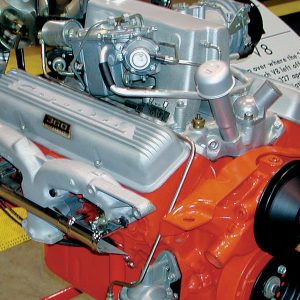
Thirty-five years and $636 ago, we bought an 80,000-mile ’62 fuel-injected Corvette in Fresno, California. Sadly, the car had been stolen once. The fuel injection was gone as well as the T-10 four-speed transmission. A pair of bare 461-X heads was in the trunk. The engine was found to have a rocking rear cam bearing, which caused oil to shut off to the rocker arms at high rpm. At the time, the prognosis was that it could not be fixed, so the motor was replaced with a ’68 350hp 327. Since 1976, the car has been in storage, along with the original engine.


In bench racing terms, most parts and systems of the automobile are easily understood, including engine internals. Even when one is not fully versed in the specifics of an engine build, itʼs easy to recognize large head-flow numbers when you hear them. You just need a base reference to know how much of an improvement those big numbers represent.
And when talking compression ratio, itʼs generally understood that this is a phase in the workings of an internal-combustion engine, in which the combination of fuel/air is compressed within the combustion chamber (cylinder), before being ignited by the spark plug. It is also generally accepted that 9.0:1 to 10.5:1 is a more acceptable compression ratio for a high-output, normally aspirated street engine, and that any ratio below 9.0:1 would be considered more suitable for a boosted application or non-performance engine. A compression ratio nearing 11.0:1 or higher is the threshold for an engine more at home on the racetrack, using higher octane than is readily available on the street.
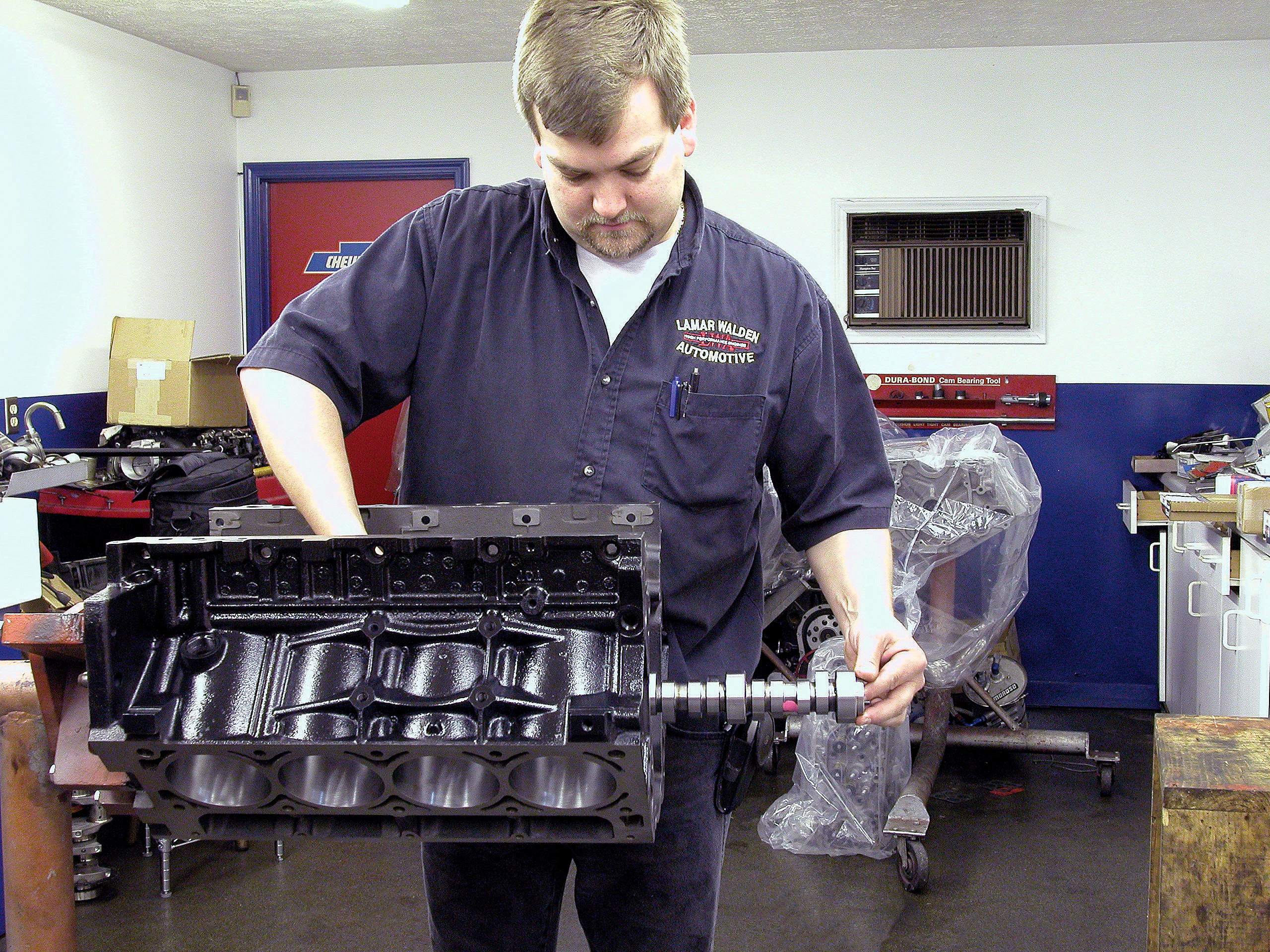
But start talking cam specs like duration, lift and overlap, or valve events as they relate to crankshaft degrees, timing and volume under the lift curve, and you begin to lose the understanding of what these mean in selecting and timing a proper camshaft. Itʼs not as important that we understand the terminology as much as how elements of cam timing can be utilized in the proper selection of a camshaft for our particular applications. There is no other component within the engine that relates to the functional operation of all your engine parts as does the camshaft, its lift and its timing.
As a result, a lot of people are running around with the wrong camshafts in their engines. They understand the importance of the cam; they just lack the knowledge and operational experience to properly select what is needed. If there is a common mistake made by most inexperienced engine tuners, it is selecting a camshaft that is too big for their applications.
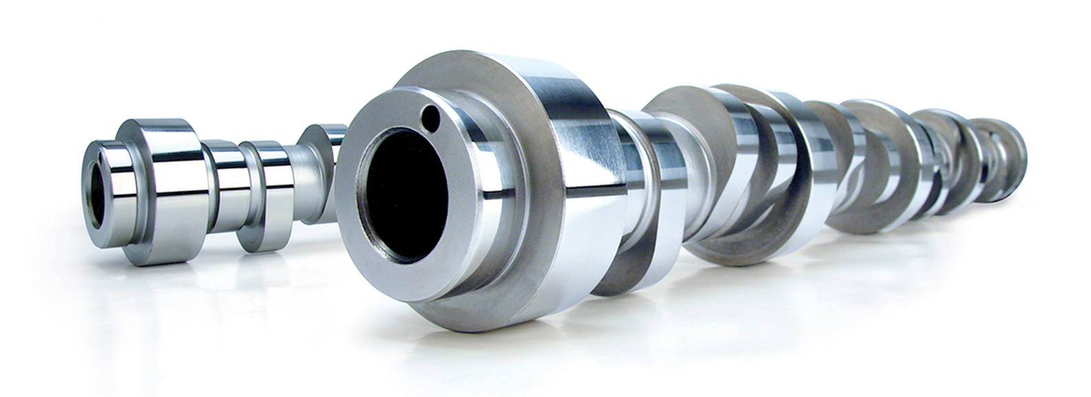
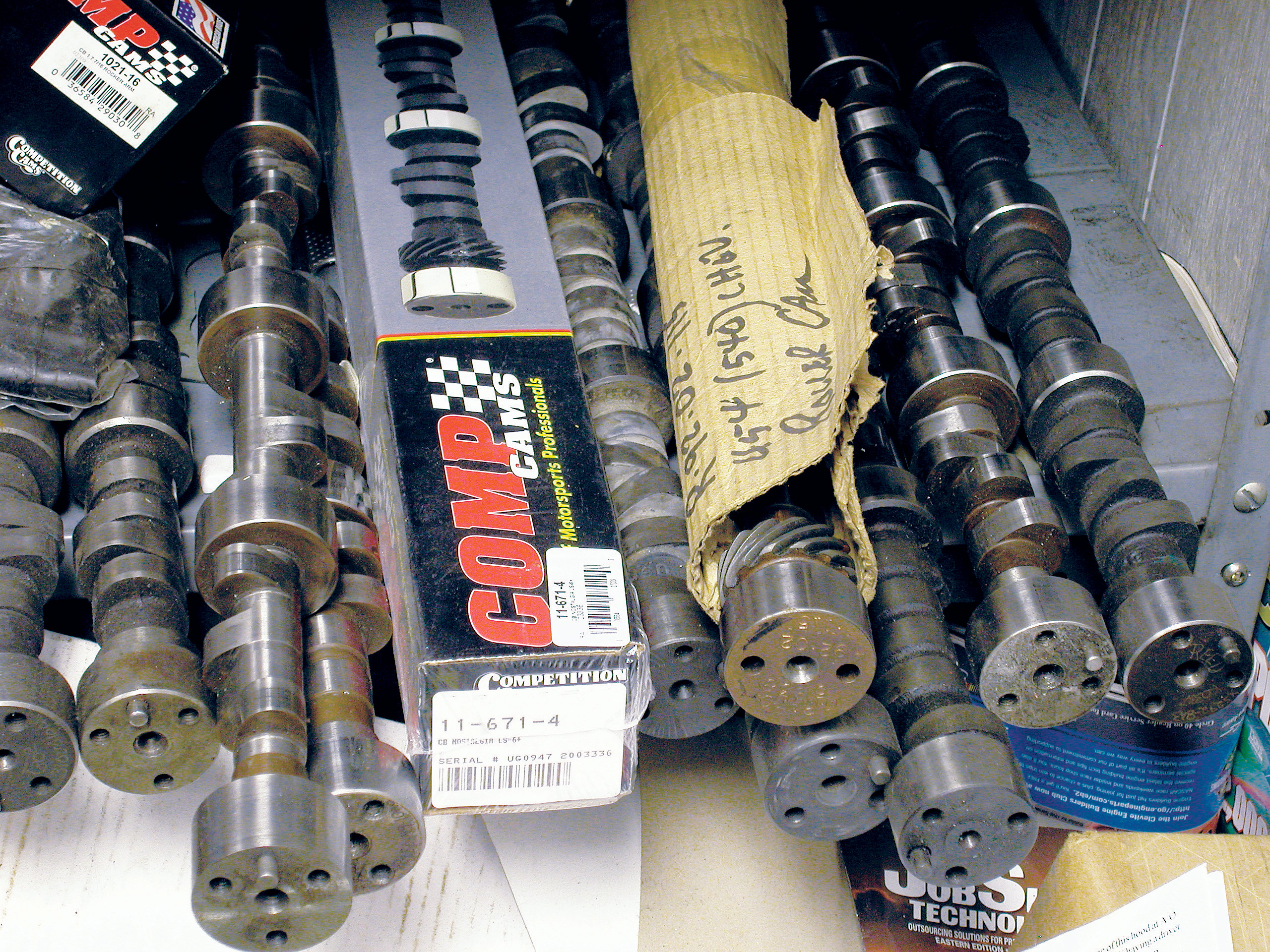
To help educate us, we took a trip to Comp Cams and spoke at length with cam designer Billy Godbold. Designing cam lobes is a mathematical science that is highly specialized. Today it relies heavily upon computers to crunch numbers for potential acceleration ramps, lifter velocities, noses, closing profiles and base circles. But thatʼs only the beginning when discussing the physical characteristics of the camshaft. When this all occurs within the engine, how the valvetrain can react to the intended cam profile is every bit as important as how much or how high cam timing events occur.
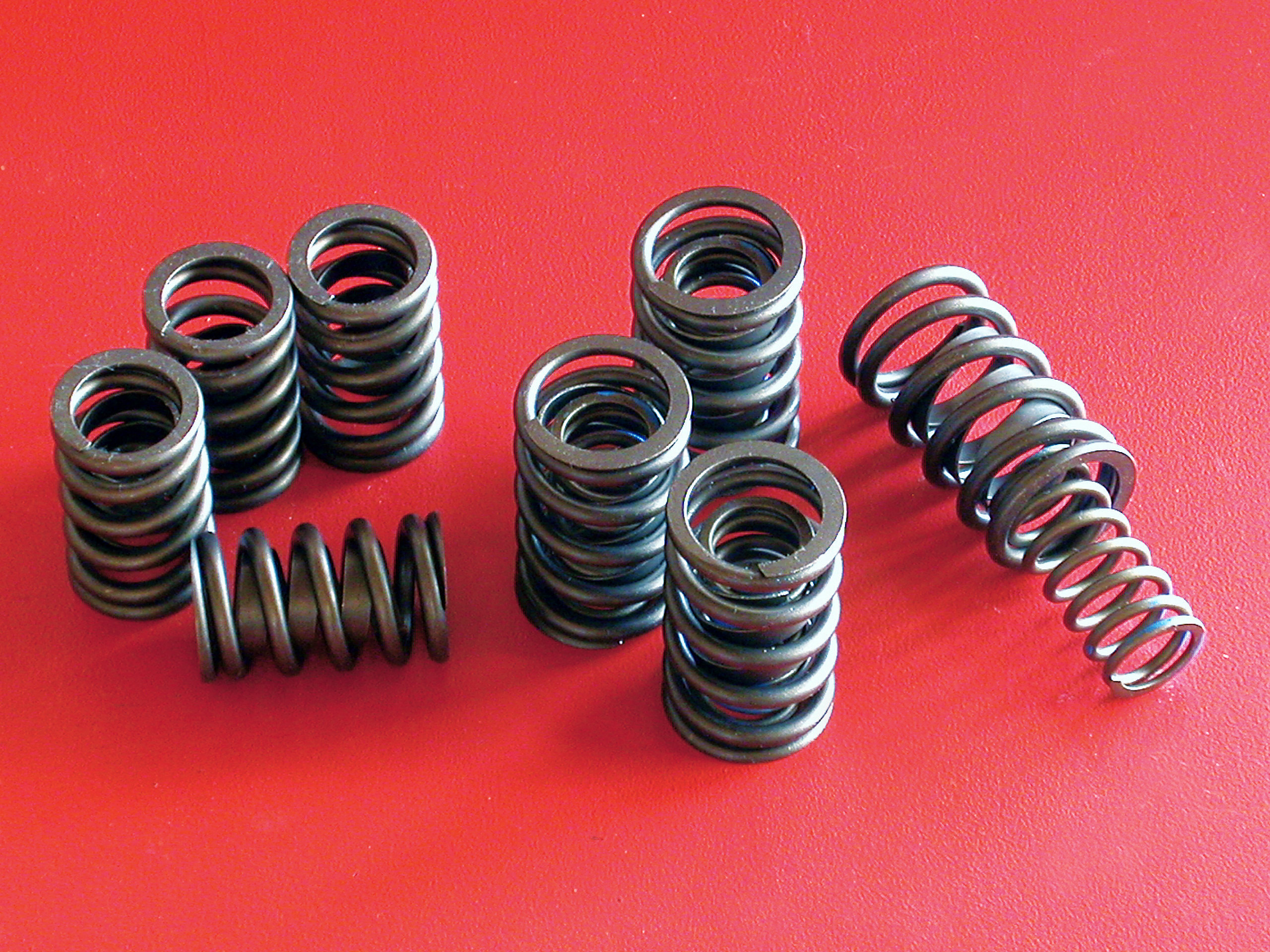
Godboldʼs professional background is in nuclear physics, and he is quick to point out that camshaft lobe and timing design is only part of the equation to building power. Controlling the valve at the other end of the valvetrain is as important as size and timing. Where Comp Cams is concerned, this task falls to Thomas Griffin. As one might imagine, Godbold and Griffin work very closely together. Griffin designs springs that will stand up to the lifts and velocities of the lobe profiles that Godbold designs. Godboldʼs job is to design lobes that will break Griffinʼs designed components (springs, keepers, retainers, pushrods, lifters and rockers). To hear Godbold tell it, he has the easier of the two jobs. To hear Griffin tell it, Billy is right.
So we asked these men about choosing cams and quickly learned that we too were nodding with glazed-over eyes. Godbold really gets excited about camshafts and their design, and will quickly outpace most anybodyʼs level of knowledge and understanding on the subject. Fortunately, he doesnʼt mind backing up and dumbing it down for those of us that are less technical.
UNDERSTANDING WHAT HAPPENS
Making the decision for what cam should be bolted in your engine boils down to simple math. Where it gets more difficult is labeling those mathematical events, and then understanding how they affect the performance of the engine in question.
To begin our explanation, letʼs start with the piston at the top of the cylinder, with both valves closed, and the spark already igniting the fuel/air mixture within the cylinder. As a direct result, the piston has started down the bore from the explosion of the gas igniting the mixture, which will last half of a crankshaft revolution and one-quarter camshaft revolution. Just before the piston reaches the bottom of the bore, the exhaust valve begins to open, allowing the force of the explosion to begin escaping out and into the exhaust port. All during this process, the exploding gas continues expanding and pushes the piston farther down into the bore. By opening the exhaust valve, the expanding gas has a place to expand and exit. The piston hits Bottom Dead Center (BDC) and starts coming back up the bore for another half crankshaft revolution, pushing the exhaust gases out the exhaust valve and into the exhaust system. As the crank continues through its revolution, the camshaft moves at half the speed to maximum lift, fully opening the valve, and then it begins to close.
Just before the piston reaches Top Dead Center (TDC), the exhaust valve is still open slightly, as the intake valve begins to open. The period of time when the exhaust valve is not fully closed and the intake valve is beginning to open is called “overlap.” Overlap is one of the most important events in the cycle of a camshaft. The exhaust stroke has expelled almost all of the spent charge, and as the intake valve opens, a scavenging effect takes place inside the combustion chamber. As the exhaust gases rush out the exhaust port, they begin to pull the fresh charge from the intake port as the intake valve opens. This flushes the exhausted gases out of the cylinder.
Once the piston passes though TDC and begins moving down the cylinder, it will suck the intake charge into the cylinder, while the valve moves into the fully open position. If the exhaust valve were open at all during this process, the piston would also suck the exhaust gases back into the cylinder, so the exhaust valve must be completely closed at exactly the right moment. If the intake valve opens too early, the piston—still on its upstroke—will push the new charge back up into the intake runner. If it occurs too late, there wonʼt be enough fuel in the cylinder, causing a lean condition. If the exhaust valve closes too early, it will trap some of the spent gas in the combustion chamber, diluting your fresh intake charge. Closing it too late will siphon too much of the incoming charge out the exhaust runner, making the engine run rich in the exhaust port.
Finally, the intake valve must be closed just after the piston reaches BDC. The quicker the intake valve closes and the closer to BDC the piston is, the more pressure will be built as the piston begins the upstroke of compression. If the piston is already on the way up before the valve is fully closed, some of the charge will be forced back out of the cylinder and into the intake port. Once the piston travels back up the cylinder, compressing the charge, the spark plug ignites it, forcing the piston back down the bore. The process then starts over again and repeats several thousand times per minute.