TheAutoBuilder.com

Necessity Breeds Inspiration

Author

Picture of Matt Emery

Matt Emery

Story and Photography

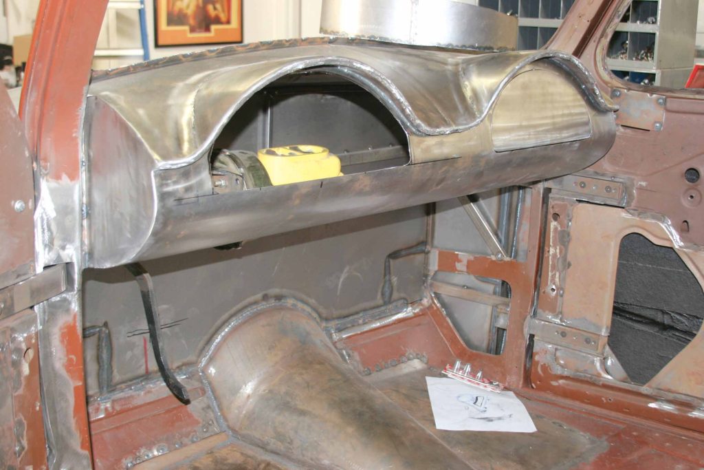
As with any buildup, once you get in to it, more seems to undergo surgery or upgrading as you go. And it doesn’t matter whether it is an old truck or a fresh new one. Mods are mods, and they always lead to more. In this case, the SRRC crew has been hard at work on a ’38 Chevy, which has been subject to many body mods and suspension changes. During this build, the crew completely removed the stock dash and fabricated a new one out of aluminum sheet. The resulting dash is turning out sweet and will even include a matching center console. So, envision your own truck and taking it to this level, even if you only upgrade the dash. But it didn’t stop here.

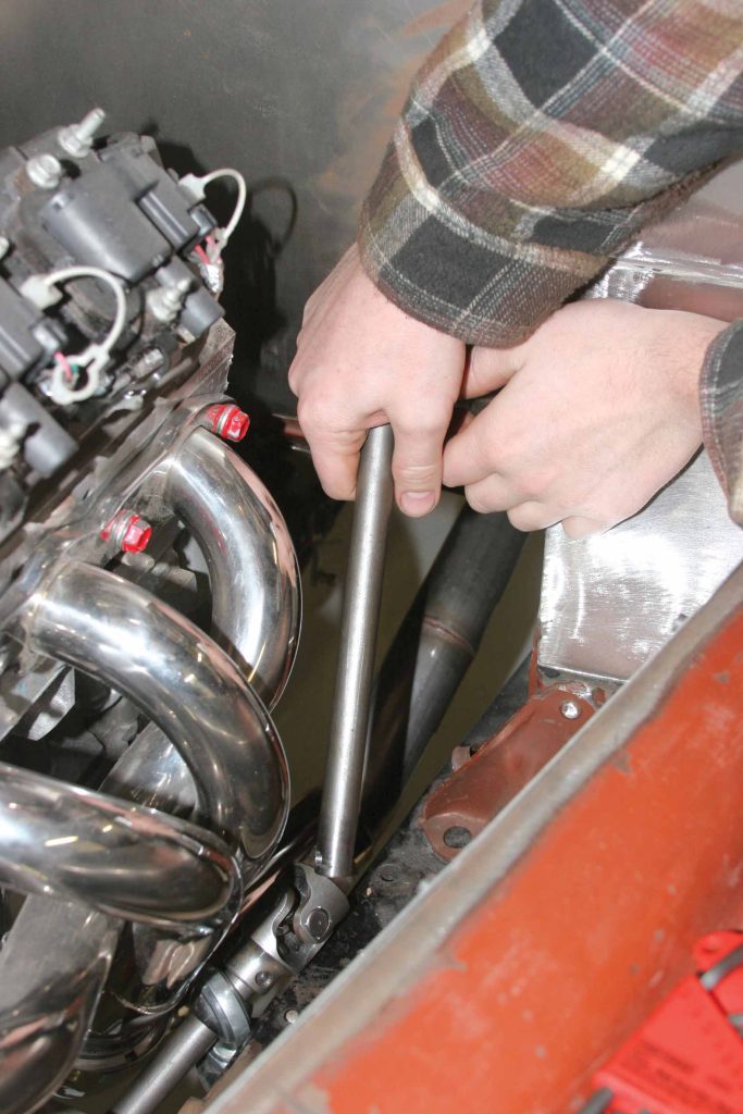
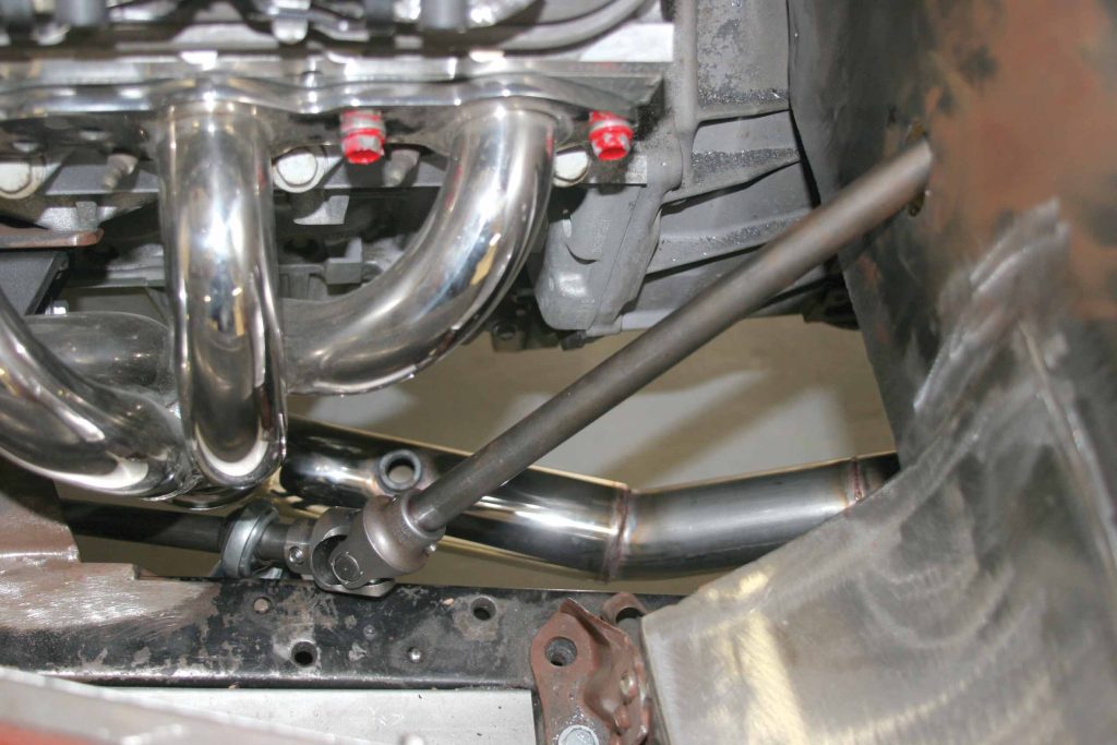
SRRC had also installed an LS1 engine in the truck, and that’s where this story really begins. While this story doesn’t have to do with installing the engine, it does have to do with installing the new ididit steering column. However, the engine had an awful lot to do with what comes next. It seems that the heads on the LS1 are (almost) exactly where the steering column would have entered the engine compartment. Something had to be changed, and it sure couldn’t be the engine location. These same considerations could happen if you were to swap another type of engine, or perhaps a big block where once a smaller six-cylinder was once located. Any number of things can affect what comes next.

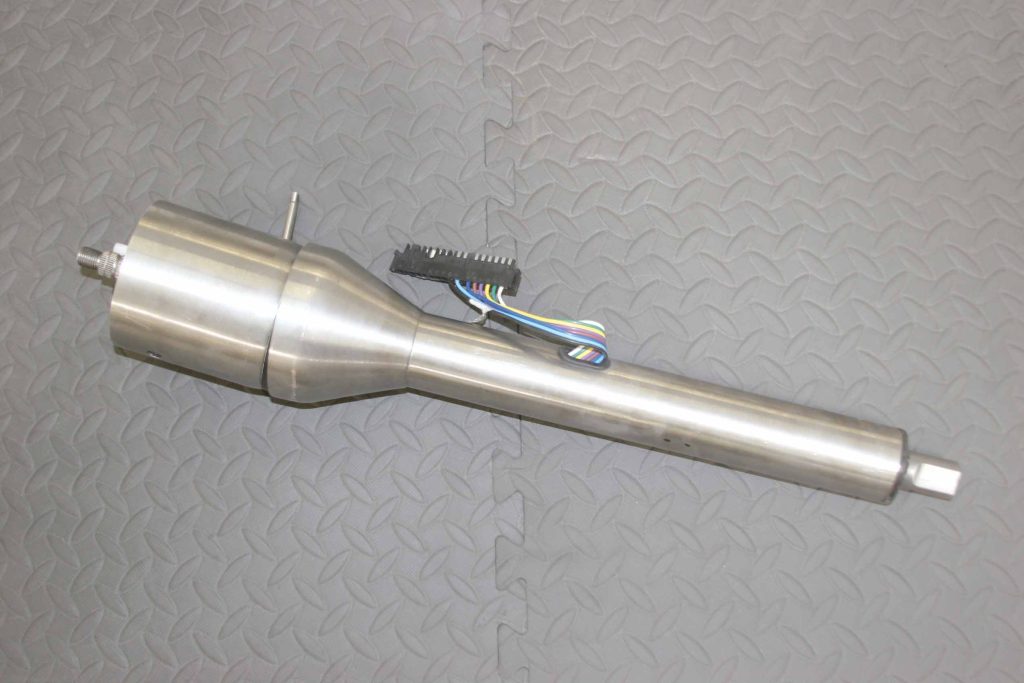
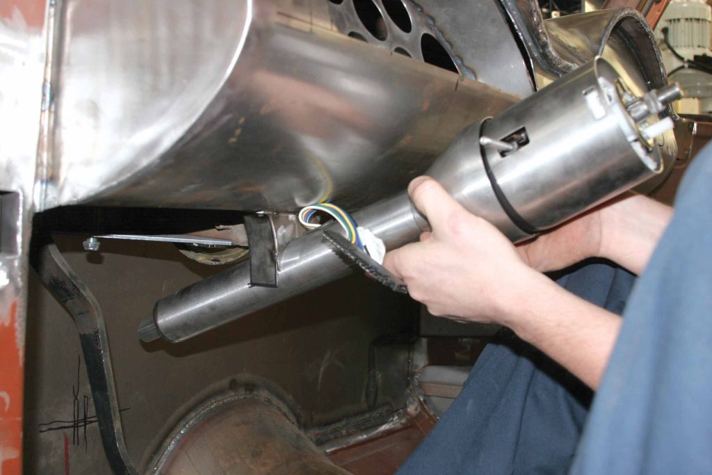
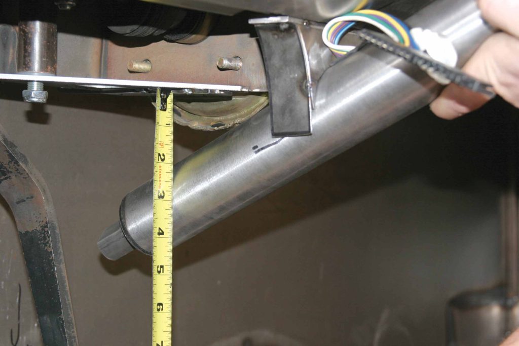
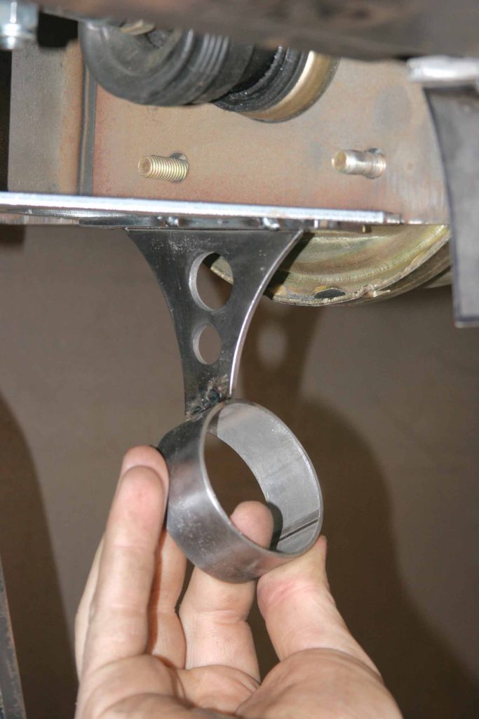
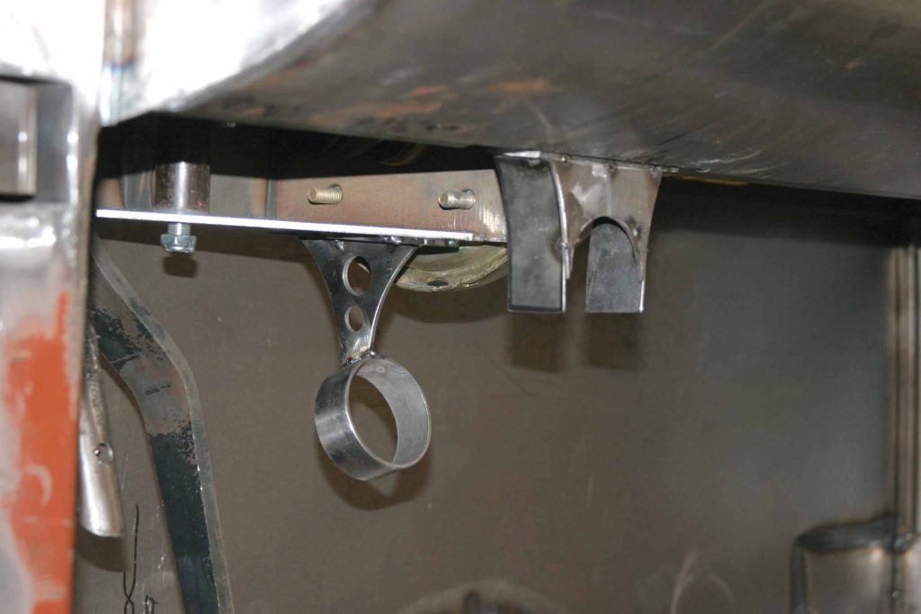
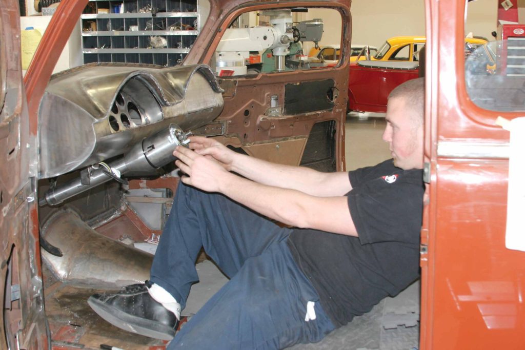
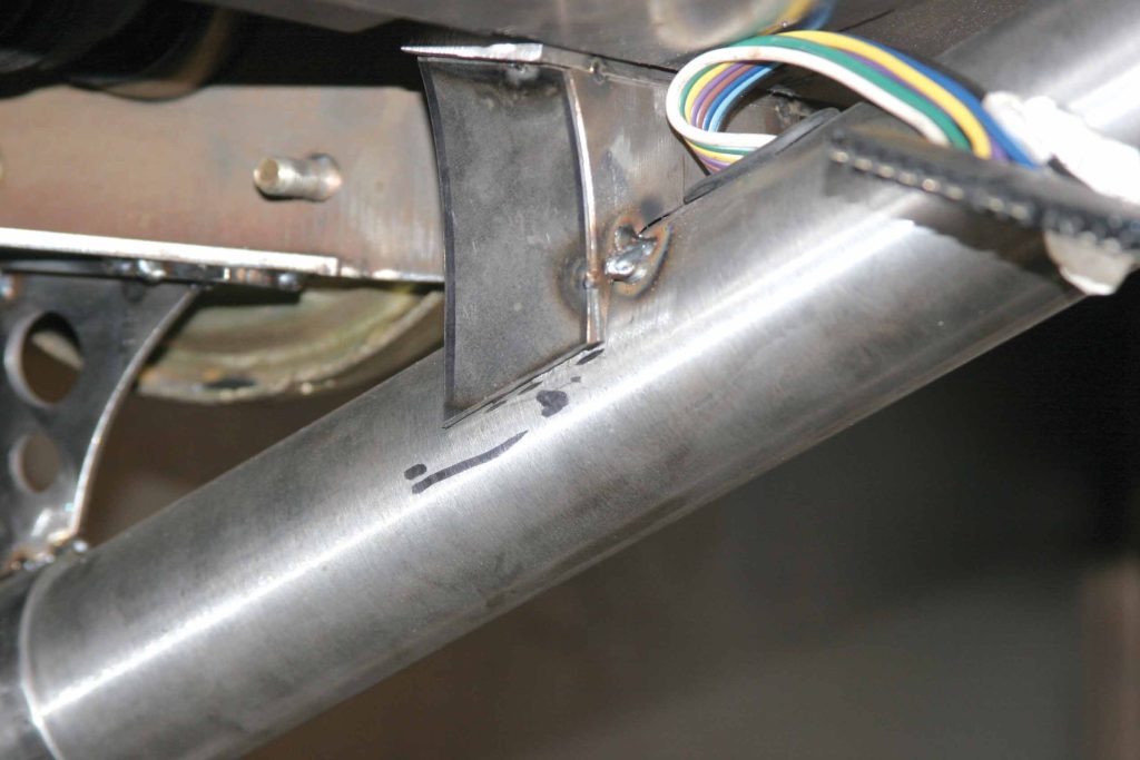
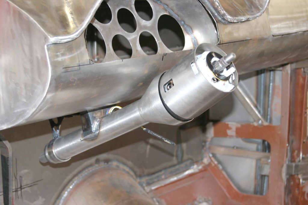
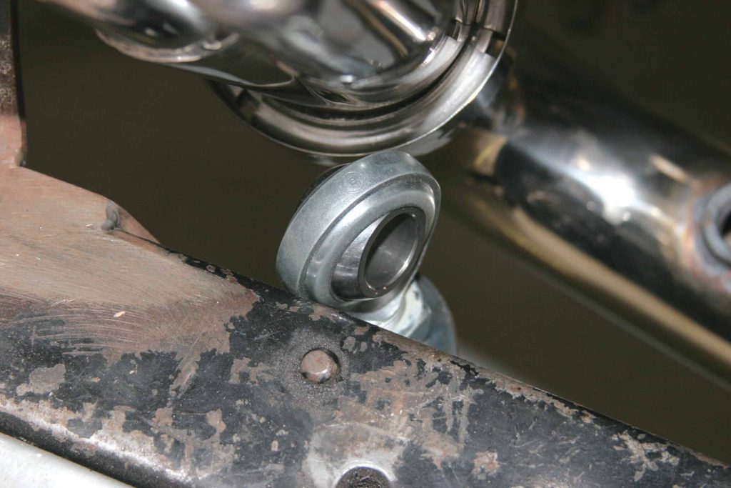
It was then that the SRRC crew figured that the engine location might be a blessing in disguise. Sure, they needed a new method to get around the cylinder head location, but they also thought the steering column should reflect the new smooth dash configuration. So, rather than run the column at a harsh angle, as so many of these installations normally do, the SRRC crew took a page from the new-car textbook and decided to shorten the column and run it up against the lower edge of the dash. This way, the column would be out of the way of the driver’s legs and could snake around the engine, and it would be cleaner looking all at the same time. If this type of application appeals to you, depending upon your needs, you can order what ididit calls its Shorty column, which is mounted with double column drops, and the steering shaft can be routed acutely in almost any manner dictated by unusual Òin the way items.

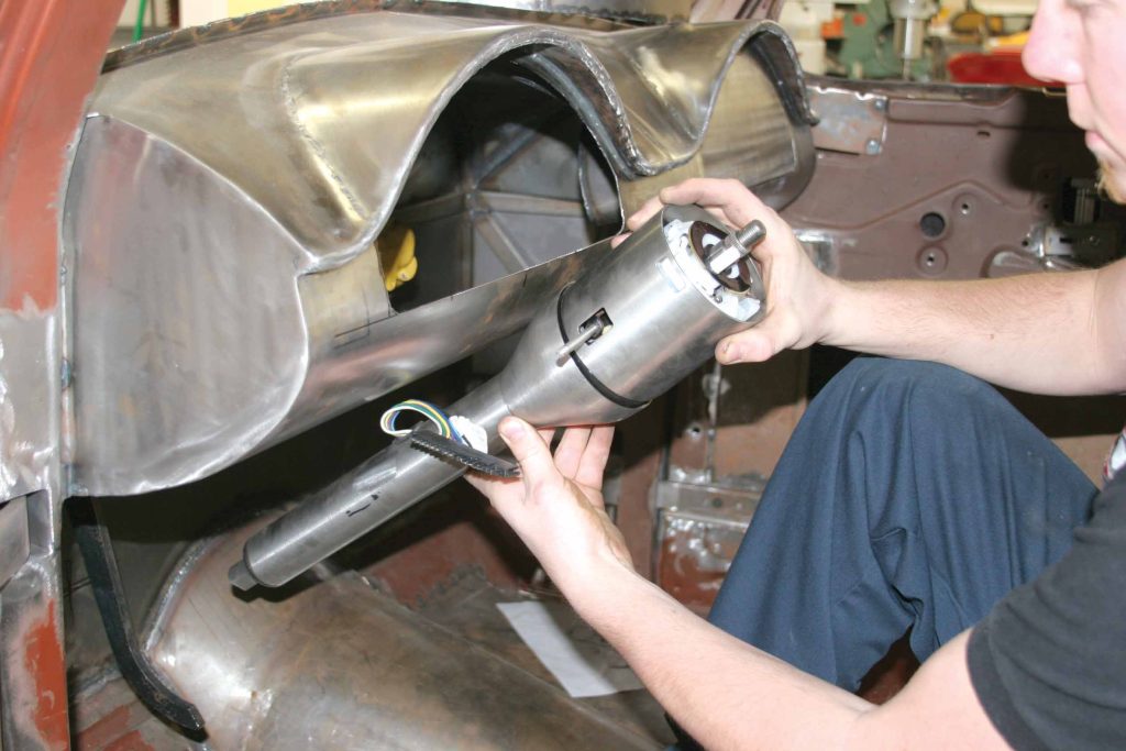
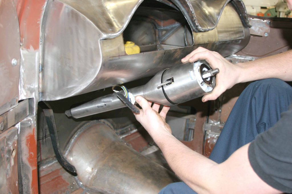
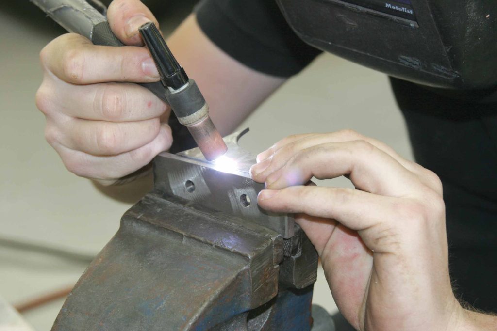
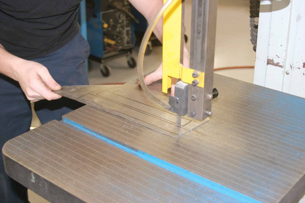
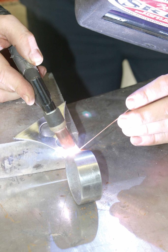
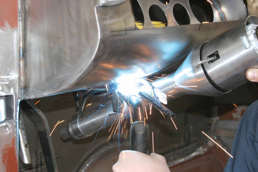
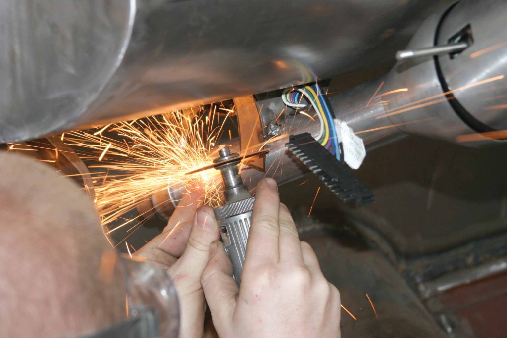
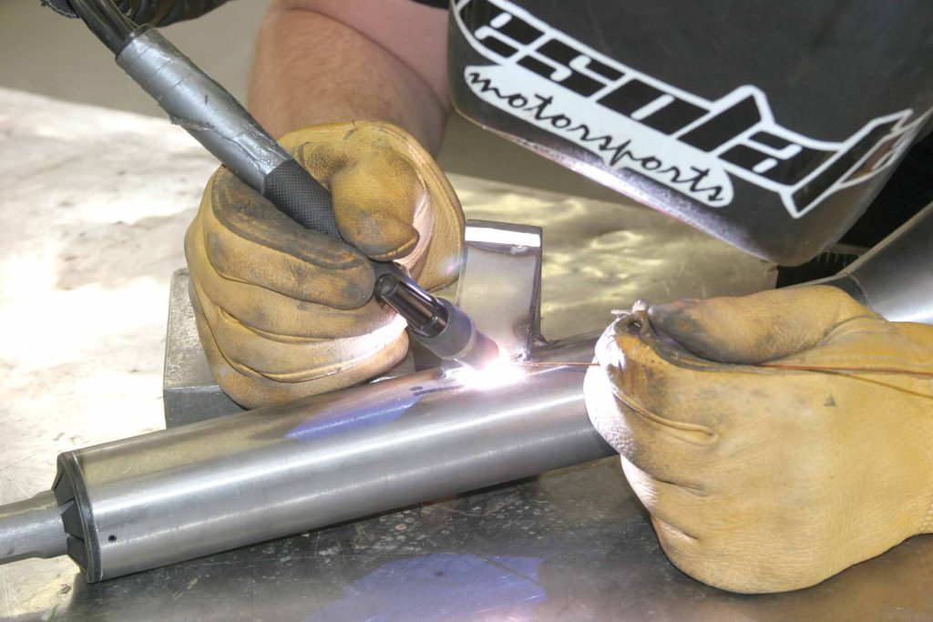
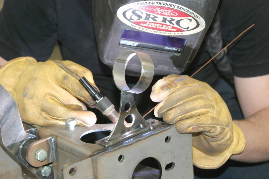
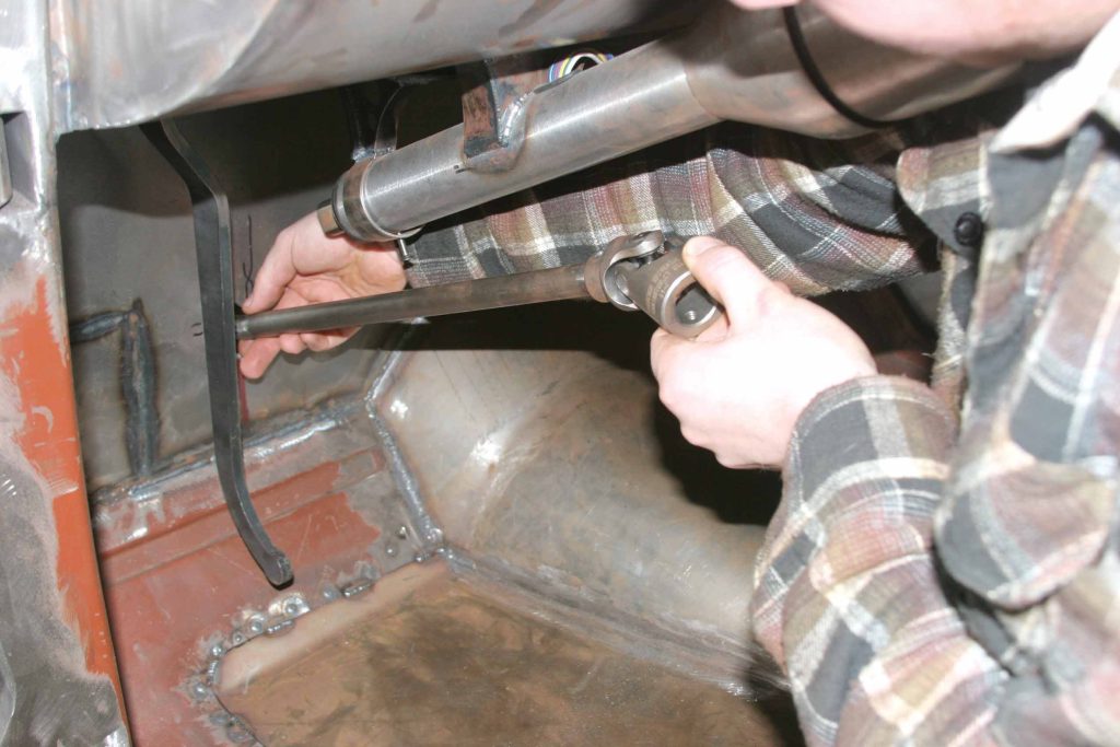
The only thing left to do in this case, and we were on hand as the crew did it, was to dramatically shorten the ididit column they had, and it worked. We followed along as SRRC employee Davey Singery made the job look easy, although for those at home this may be a job best left to a professional. That all depends on your skill level, as there are two areas that you want to make certain are safe and correct: the brakes and the steering system. Obviously, as demonstrated here, the SRRC crew can help you out with either or both. But to figure out for yourself the level of talent that such an install and modification requires, tag along here.

1 The ididit column was actually 10 inches longer than what you see here. Singery cut off 8 inches of the inner shaft and then removed 10 inches of the outer housing. This will give the desired length.
2 The first shot shows the angle at which most new columns are installed. They run all the way to the floor, where they are affixed with a base mount. This is all well and good, but the column tends to be in the way of the feet when driving.
3 This shot shows the angle at which Singery wants the column to sit. The job starts with the ididit column held up at the approximate angle that the crew was looking for. Barry White believes this will keep the column out from between the feet of the driver and will give the interior a much more polished look.
4 To make the upper mount, a paper template was first made. It will be traced onto the steel and cut out. But notice how large the initial paper template was. It was during the fitting process that the piece was eventually whittled down to what you see.
5A A piece of heavier-gauge steel was used for the mounting flange, and lighter pieces will make up the rest of the mount.
5B
6 To mount the new dash, they have built a frame that runs beneath it. It is to this frame that the upper mount for the steering column will attach. With the mounting position determined, the holes were drilled. They will also be tapped so that no nuts will be needed.
7 The new upper mount was loosely bolted up.
8 A quick check of the column showed that the job was on track.
9 With the upper mount in the right place, it was determined what drop length the rear mount needed to be. The rear mount will attach to the master cylinder mount.
10A Time to fabricate the lower mount. The pieces for the lower mount were cut using a band saw. They were bent, drilled and shapedÑand at last tack-welded together.
10B
11 The lower mount was held in place with a few tack welds.
12 Here is what the mounts will look like. There will, of course, be some finish welding and smoothing, but this is basically what will be holding the column in place.
13 The column was held in place and the fit was checked. Things were looking good at this point, so a few tack welds were put in place to hold the pieces.
14 Singery takes a good look to ensure that the column is lined up straight. He likes what he sees.
15A-B Wanting the finished product to look as good as it works, a few customizing touches were done. First, it was decided to angle-cut the ends to give a cleaner look to the affair.
15B
16 With that, the column was pulled back out and put on the bench. The welding was finished up using a TIG welder.
17 The lower mount also was finish-welded to the booster bracket.
18 With the welding finished, the column was set back in position. Now it is time to determine how the linkage will connect the column to the steering assembly.
19 Because the linkage needs to clear the headers as well as the head, the linkage is actually fabricated from the rack back to the column. The first step was to locate the heim joint. It was attached to the frame after a straight run away from the steering rack. Note that the SRRC crew actually used wooden dowels to determine the runs rather than steel.
20A With the initial run determined, it was time to cut a hole in the firewall. The upper section of linkage was fed through the hole and connected to the Borgeson U-joint.
20B
21 One word about U-joints. They need to be clocked. That is, they have to be oriented in a specific way. If they are not clocked, they will bind up when turned, and the action will not be smooth. Notice that the outer sections have their tongues (for lack of a better word) aligned toward each other. This is the correct position in which they have to be installed.
22A Another safety tip from SRRC. They will drill through the shaft and use hardened steel pins when connecting the U-joints.
22B
23 Here is the final linkage assembly. Again, notice that the U-joints are all in the clocked position.
24 With the linkage in place, there is plenty of room to get around the headers. And although the angle of the linkage may look severe, with the joints clocked, the action of the linkage is smooth, with no binding.
25 And that's it. The angle of the steering column has more of a modern feel to it, and the added foot room will be a real help when on the road.

ARTICLE SOURCES

Picture of Barry's Speed Shop

Barry's Speed Shop

(Barry White's Street Rod Repair Co.)
1640 Commerce St.
Corona, CA 92880

951/273-9284

Picture of Borgeson Universal

Borgeson Universal

187 Commercial Blvd.
Torrington, CT 06790

860/482-8283

Picture of ididit, Inc.

ididit, Inc.

Dept. TB
610 S. Maumee St.
Tecumseh, MI 49286

517/424-0577

Download WordPress Themes
Premium WordPress Themes Download
Download Premium WordPress Themes Free
Download WordPress Themes Free
online free course
download coolpad firmware
Download WordPress Themes Free
udemy free download
Scroll to Top