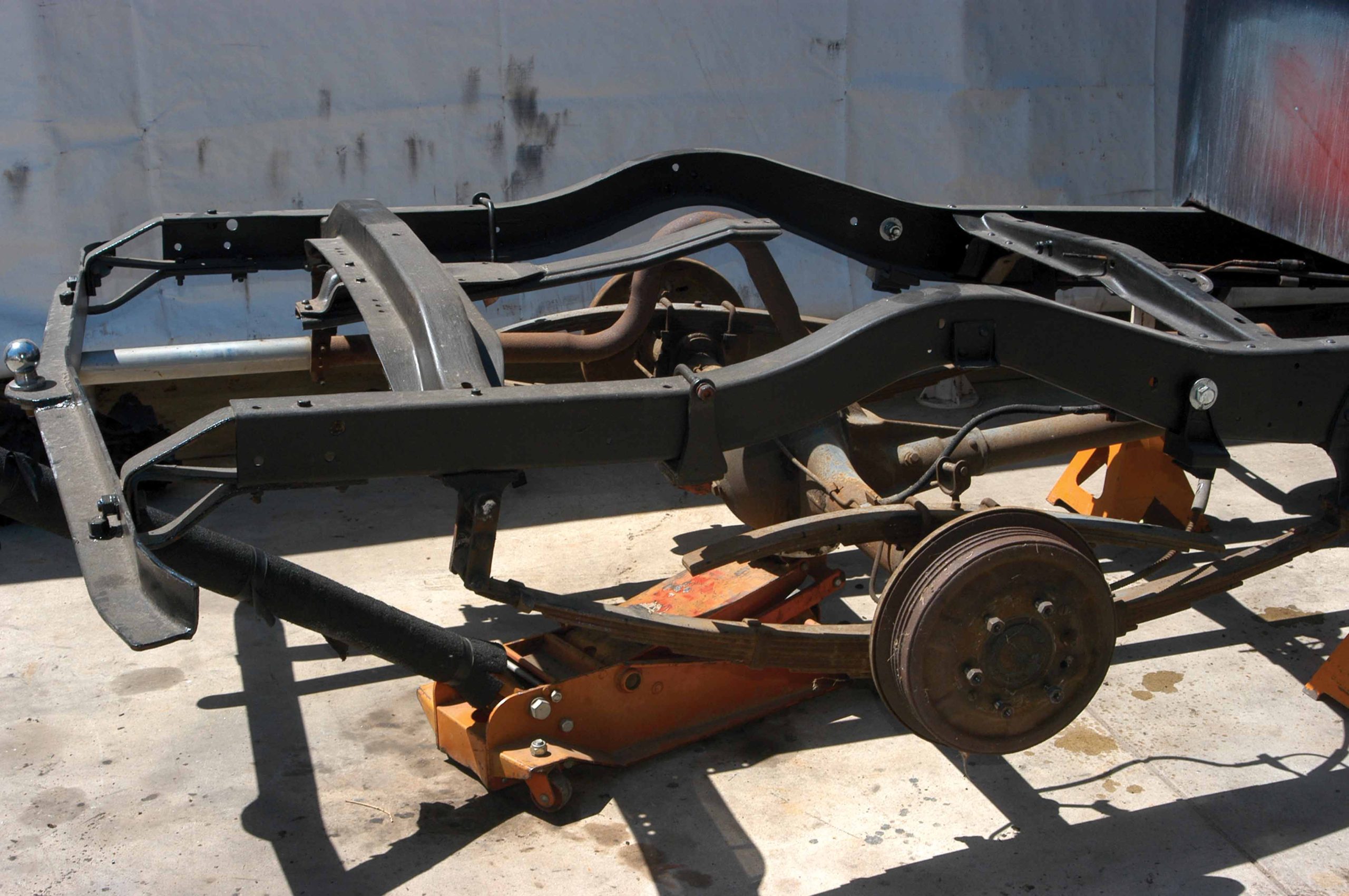
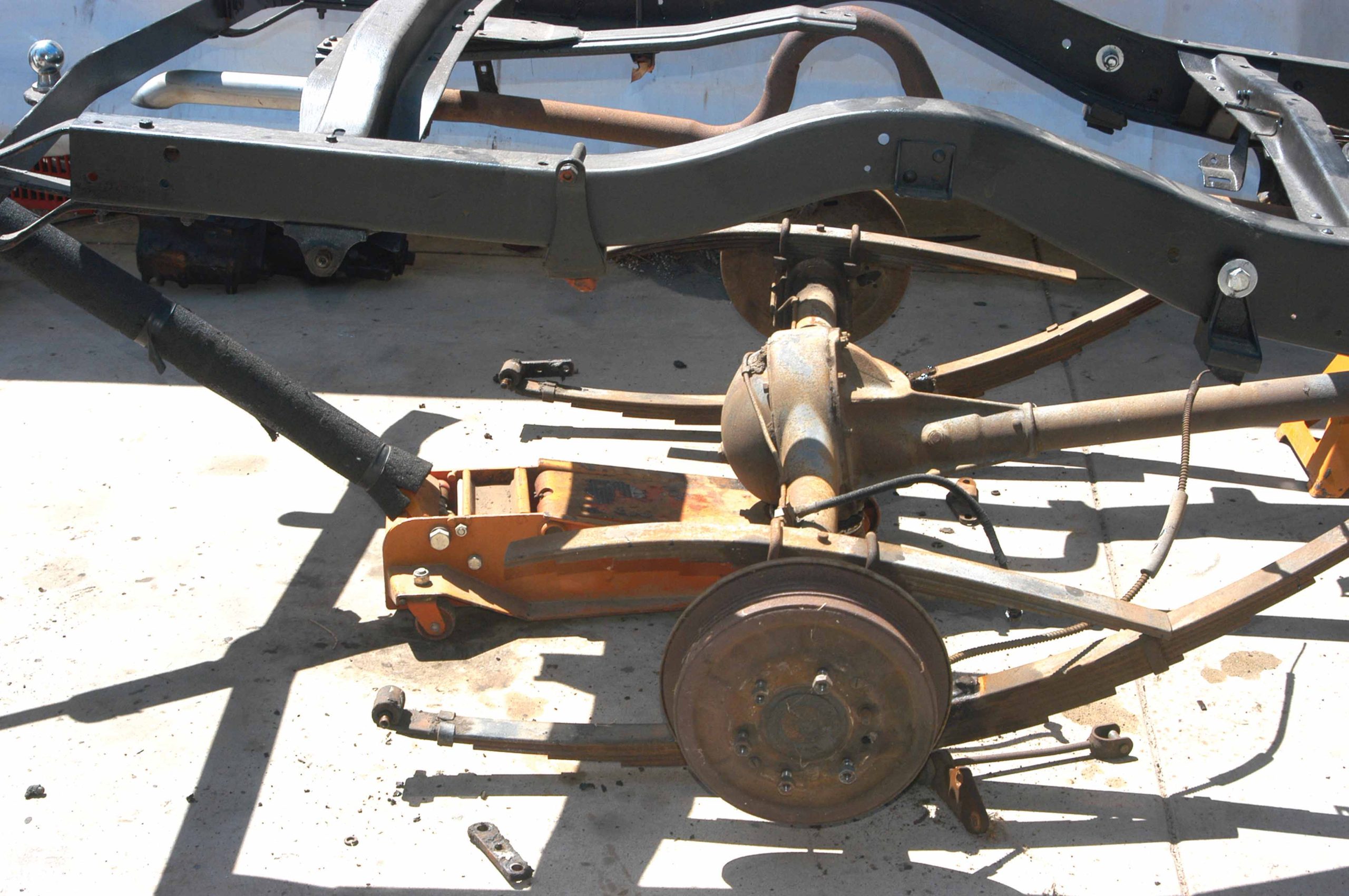
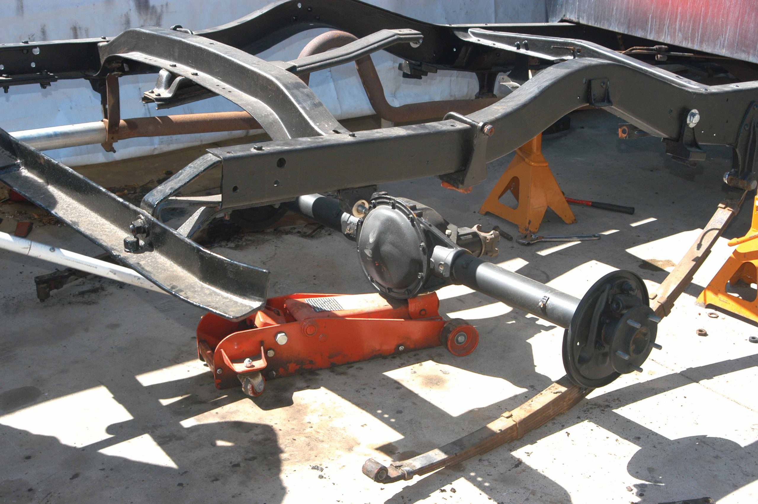
1 Like all early Chevy trucks, this ’40 Chevy was equipped with a torque tube differential mounted on dual parallel leaf springs with upper-mounted overload springs. That would all go away, as the new engine will require the differential to be an open style. Since this truck will be used for pleasure driving, the overload springs are no longer necessary.
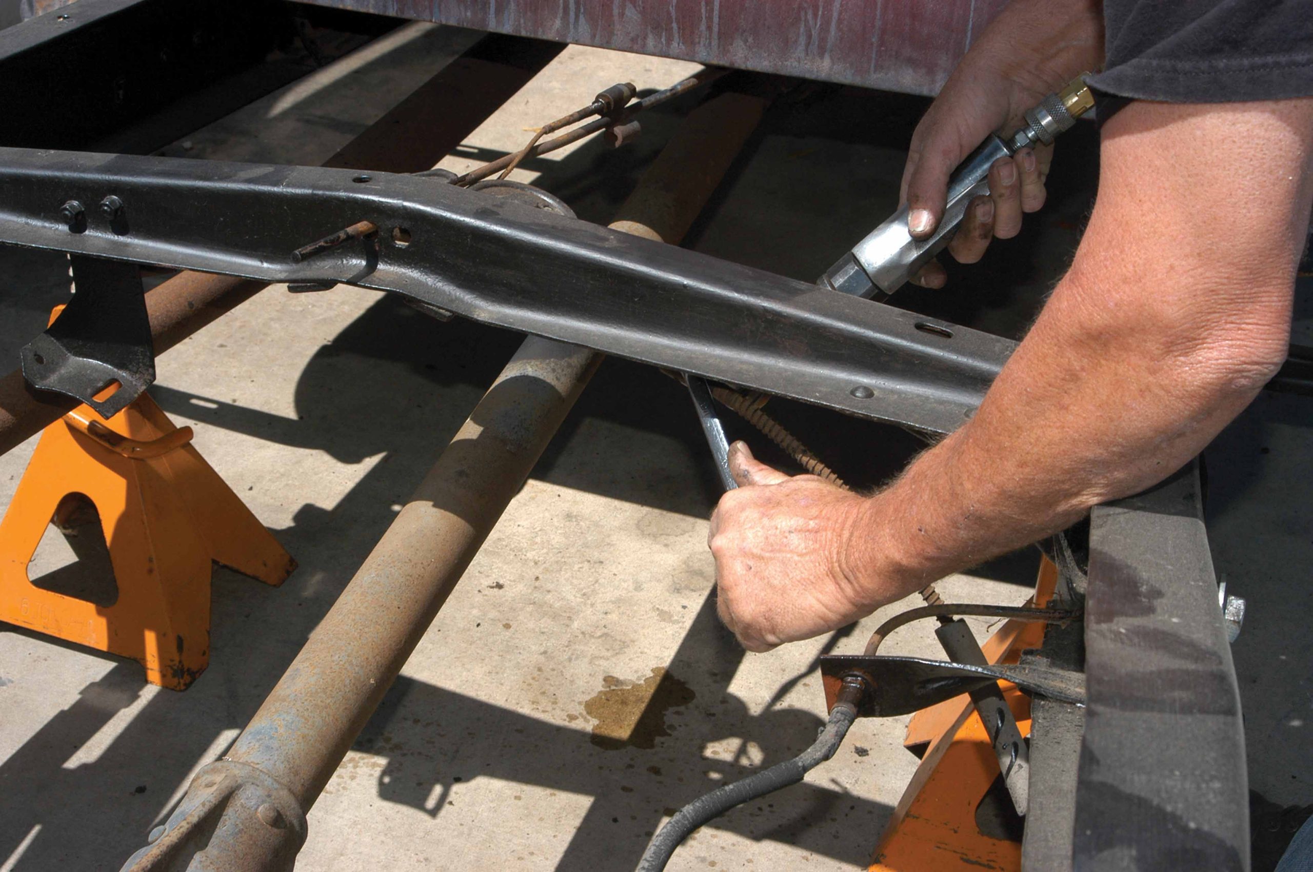
2 The bracket that holds the emergency brake line to the frame was disconnected with a box-end wrench and an air ratchet.
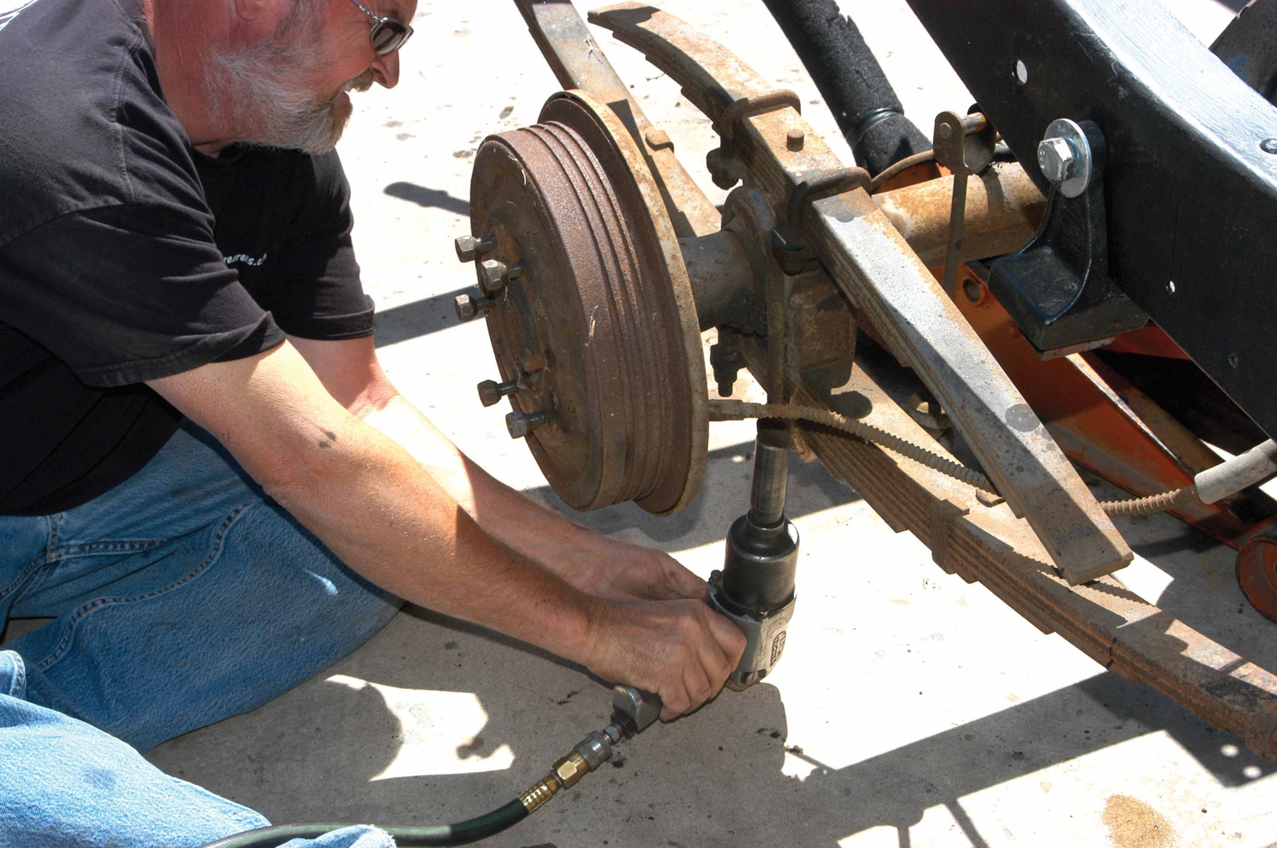
3 The rusty old U-bolts were coated with penetrating oil, and then the nuts were removed with an impact gun.
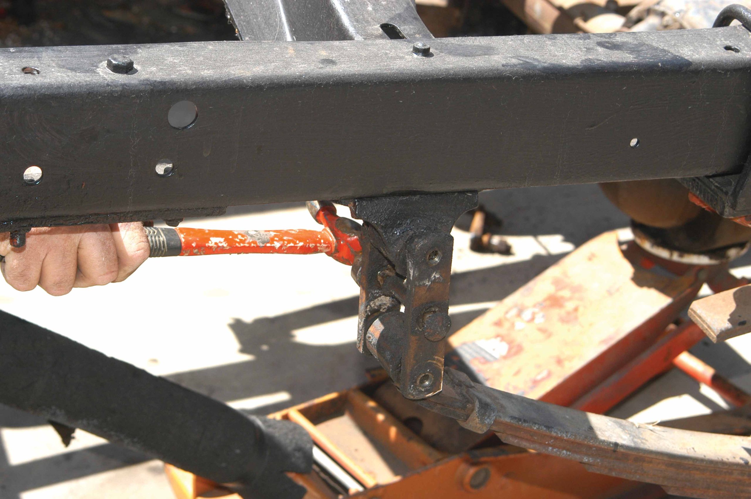
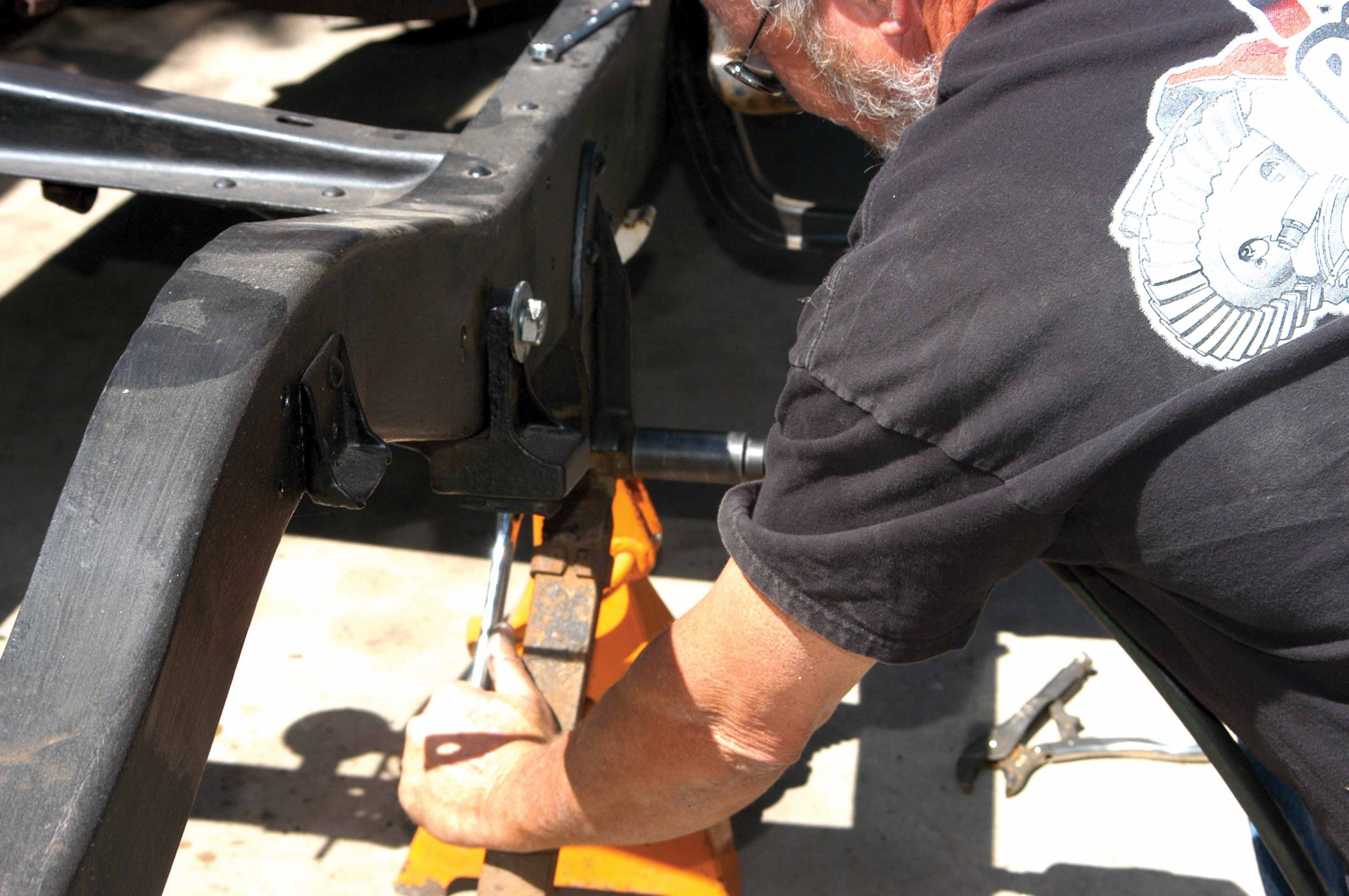
4 The grease fittings were removed from the spring and perch side of the shackle. The shackle cannot be removed when these fittings are in place. If the fittings are in good condition, they can be reused but new ones came with the rebuild kit.
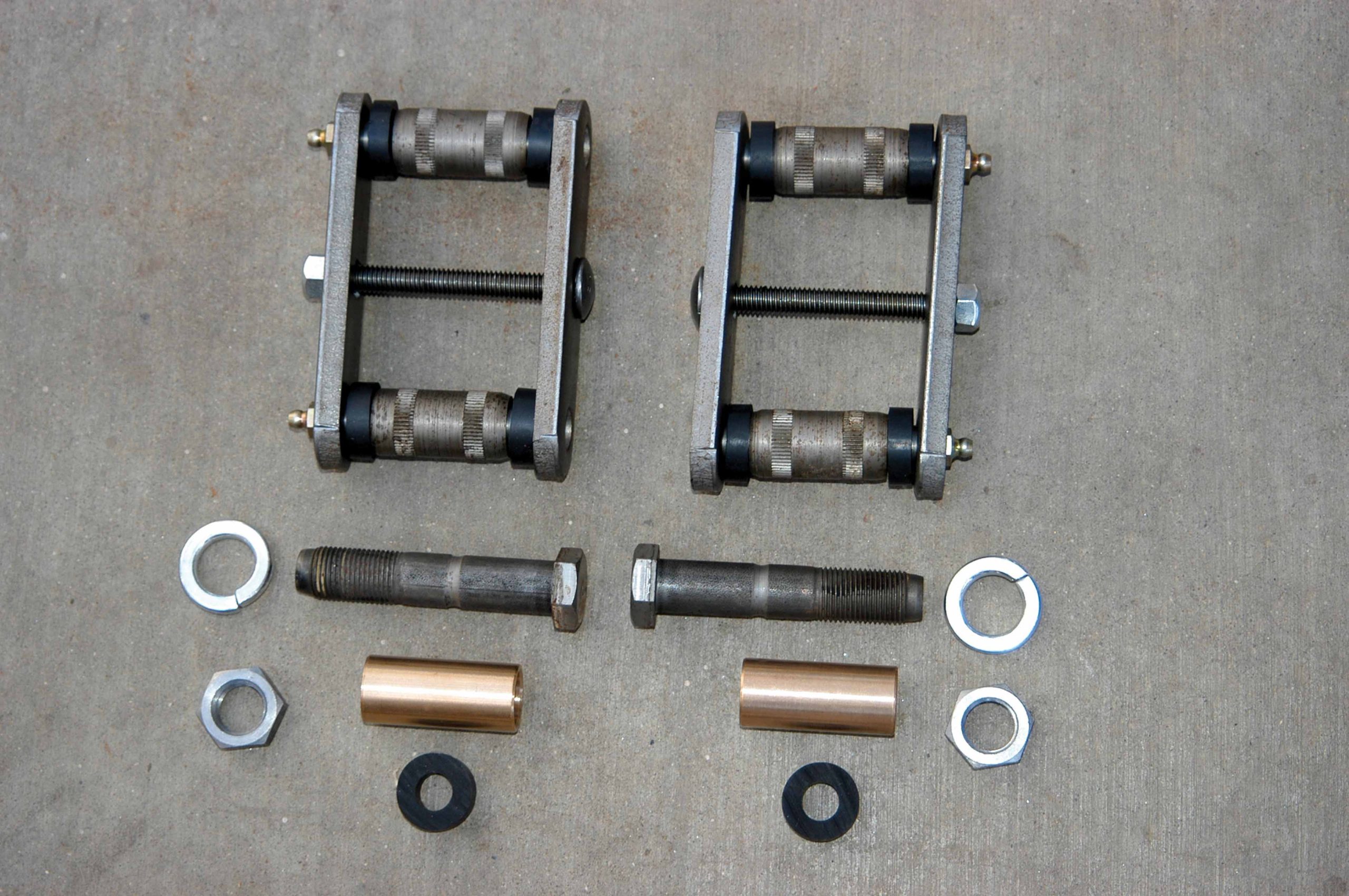
5 The shackles are held in place with a large center bolt. Here, the nut is being removed from the bolt.
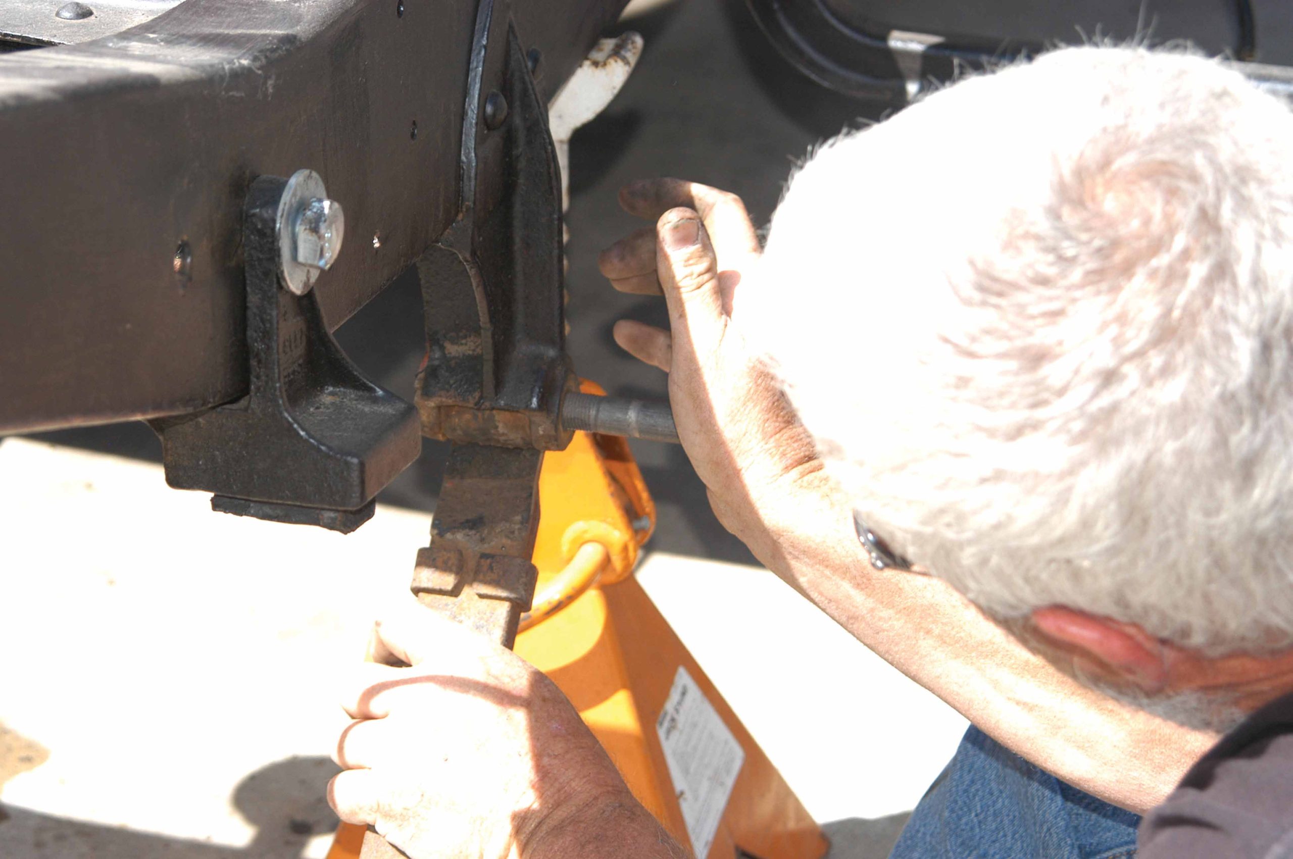
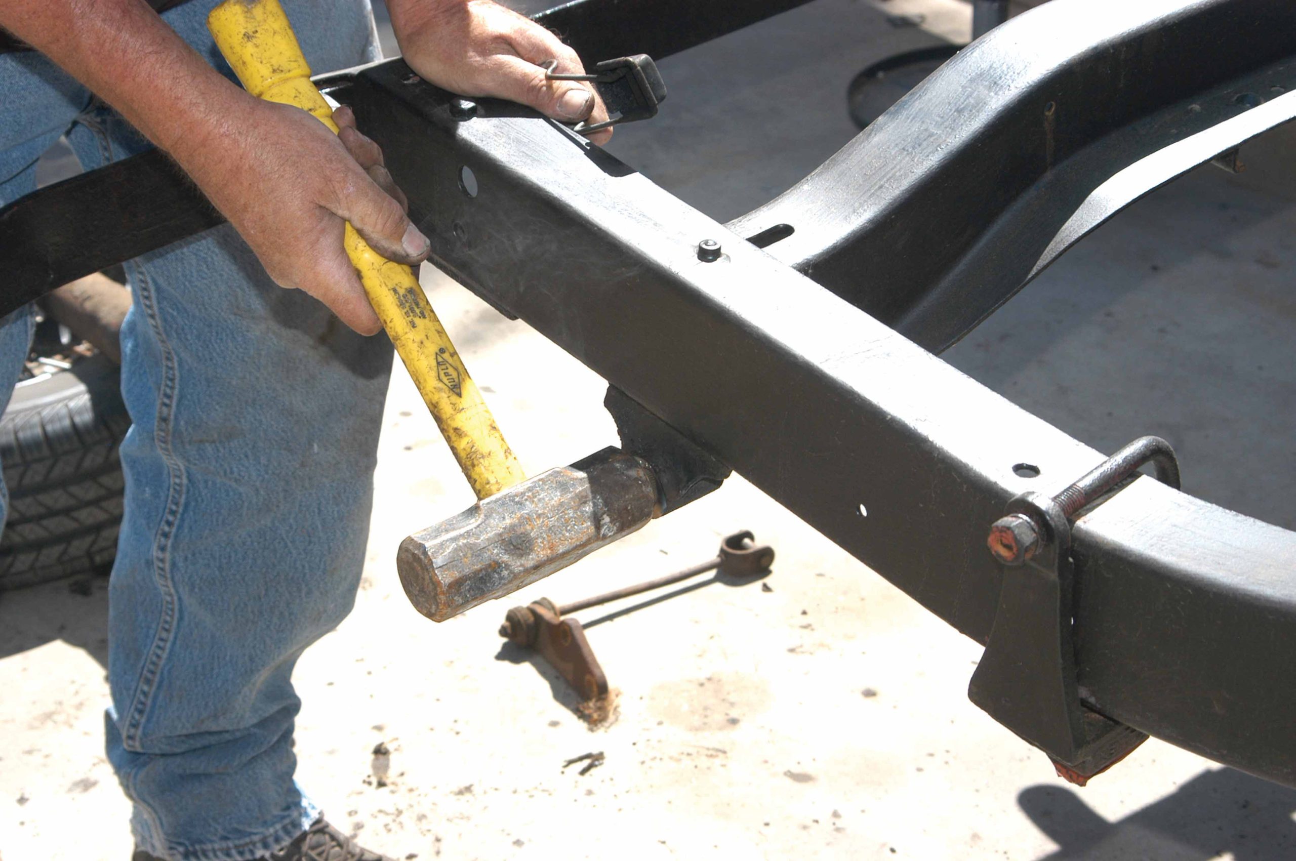
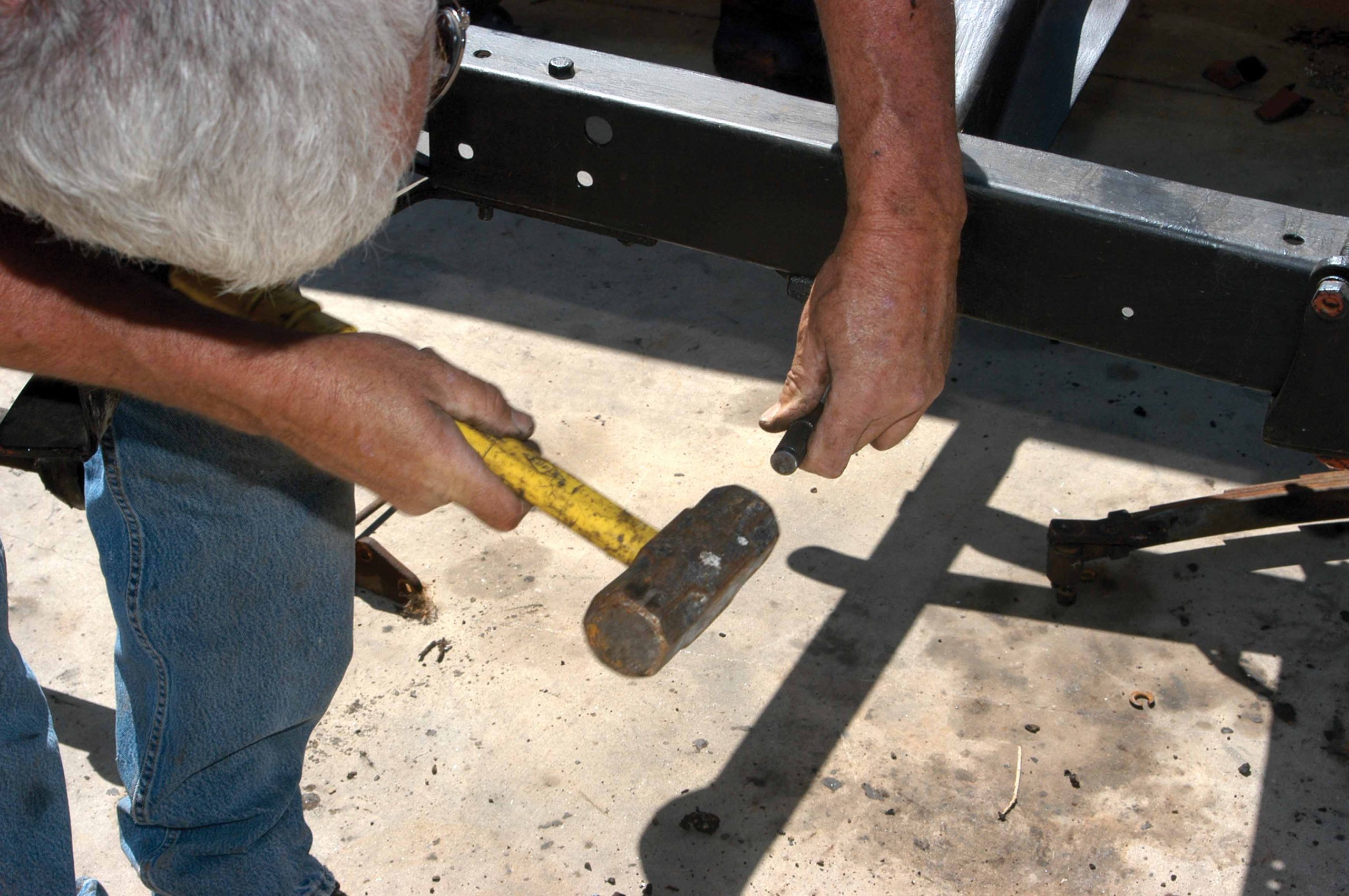
6 A hammer was used to tap the bolt out of the shackles. After the bolt was removed, the shackles can be disconnected from the spring and perch.
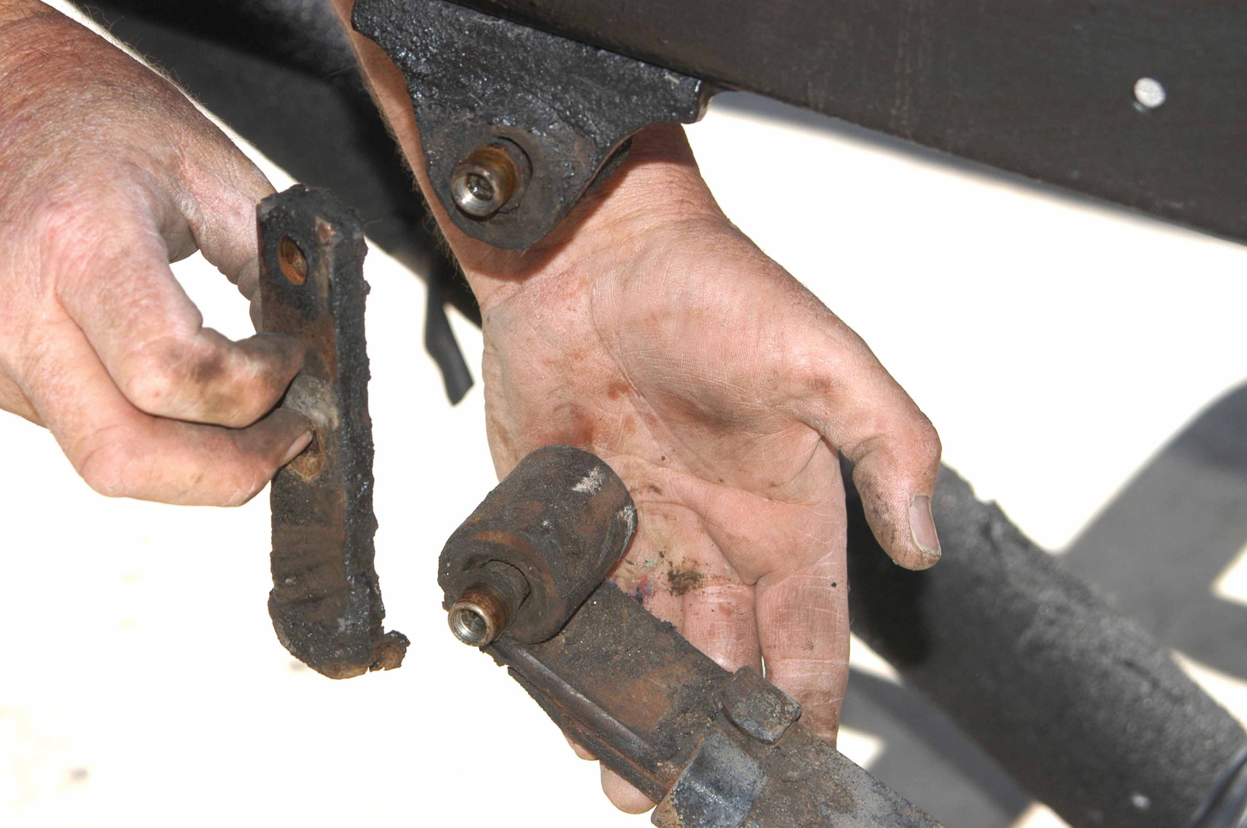
7 Here is the shackle after it was removed. Notice that the shackle bar slides onto the steel bushings.
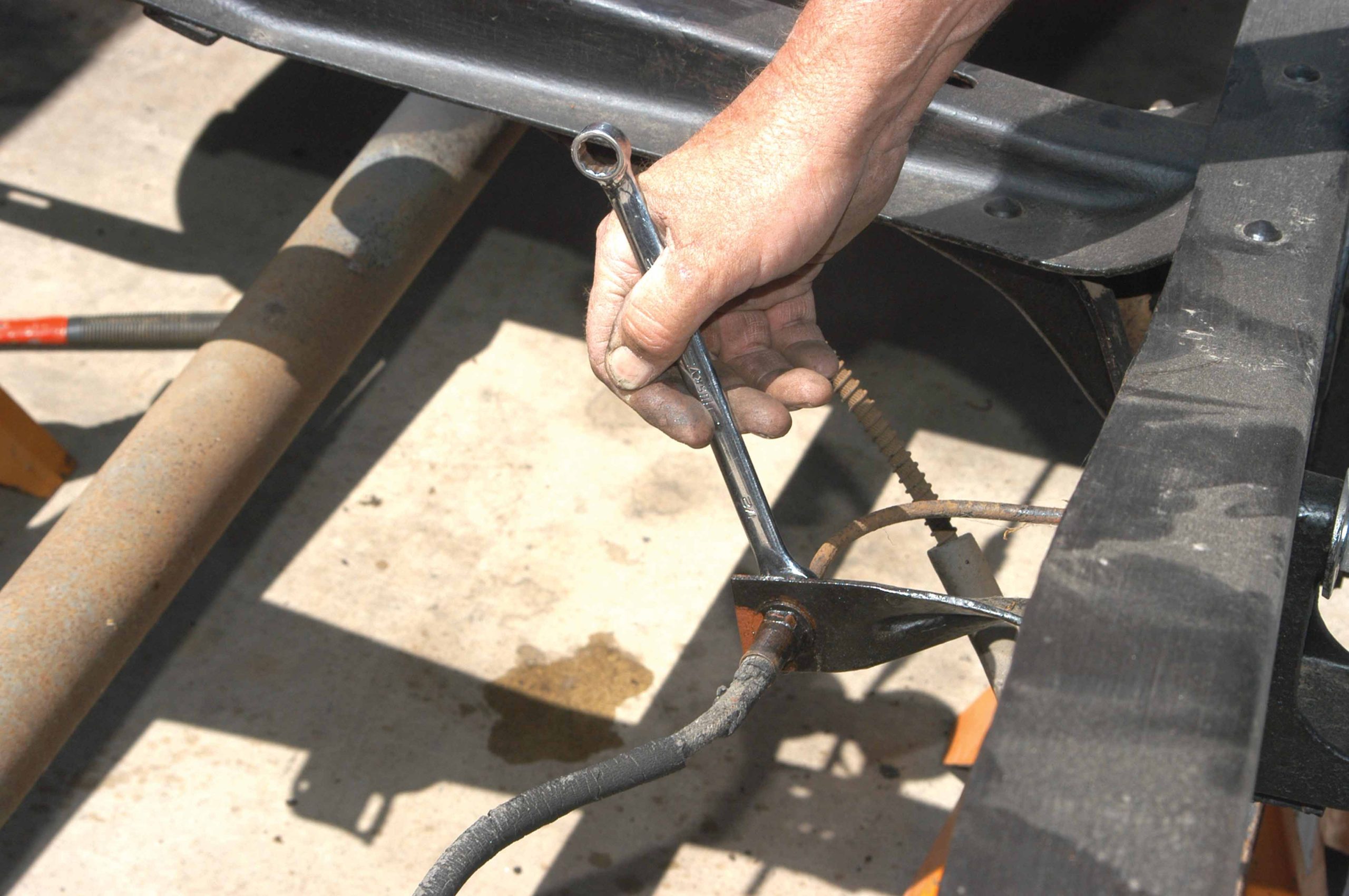
8 The brake line was removed from the brake hose with a standard wrench, but a flare-nut wrench could also be used.
9 The clip that holds the brake line to the bracket was also removed with Vise-Grip pliers.
10 The differential that is resting on a floor jack was removed from underneath the truck chassis.
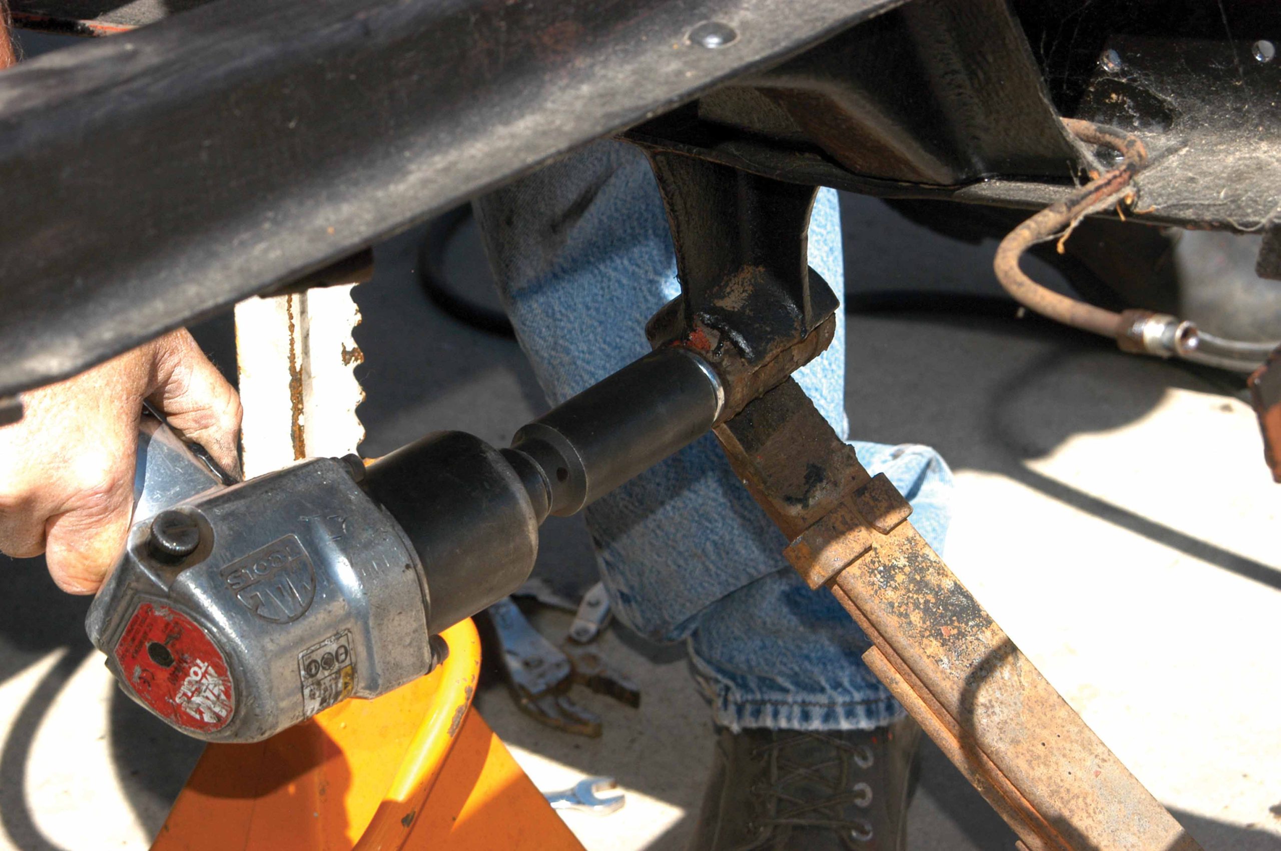
11 Using an impact gun and a box-end wrench, the front perch bolt was removed.
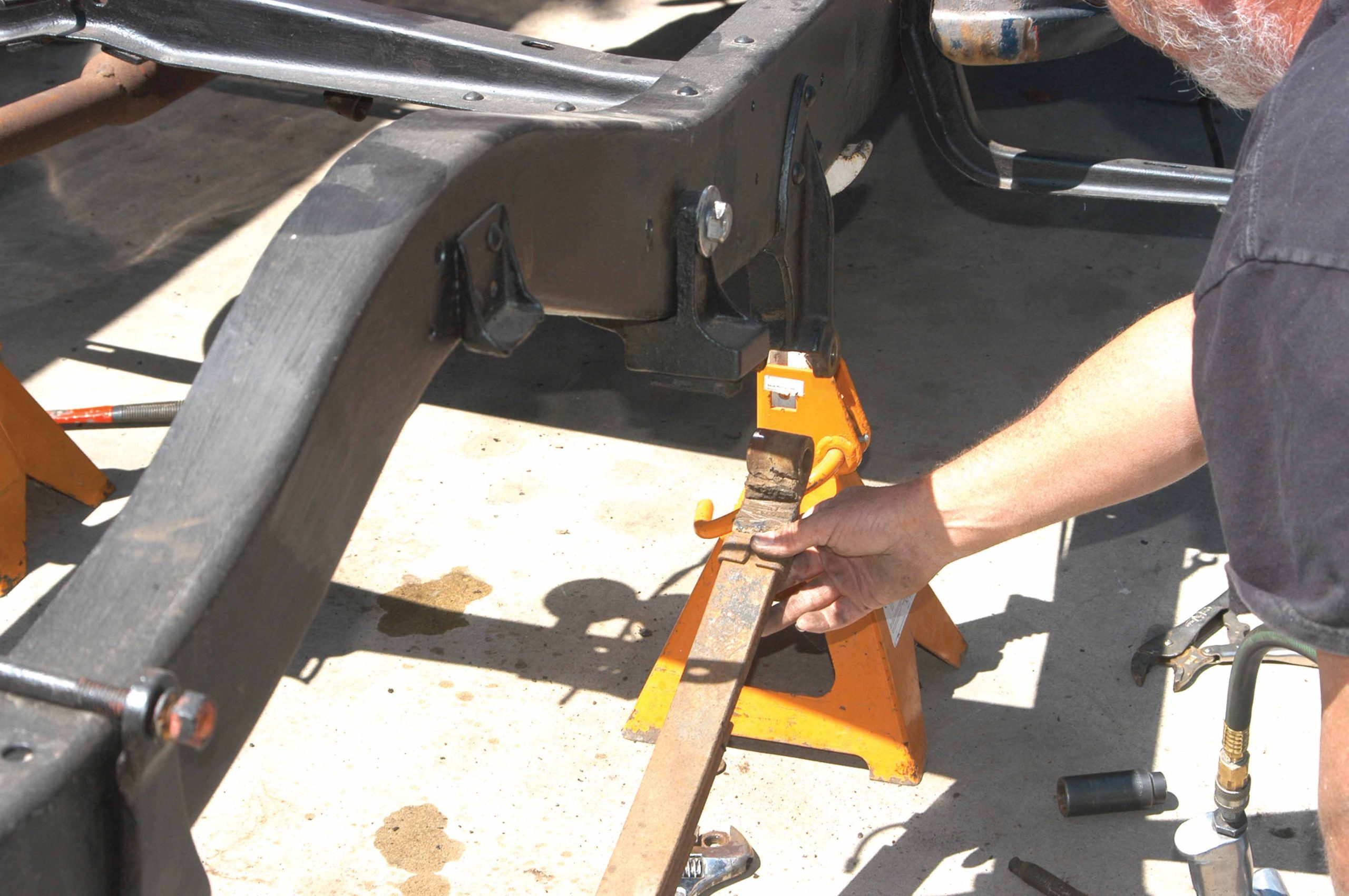
12 Here is the spring after it was removed from the front perch. The inside of the spring has a bushing that needs replacement. In this case, the bolt runs through the bushing.
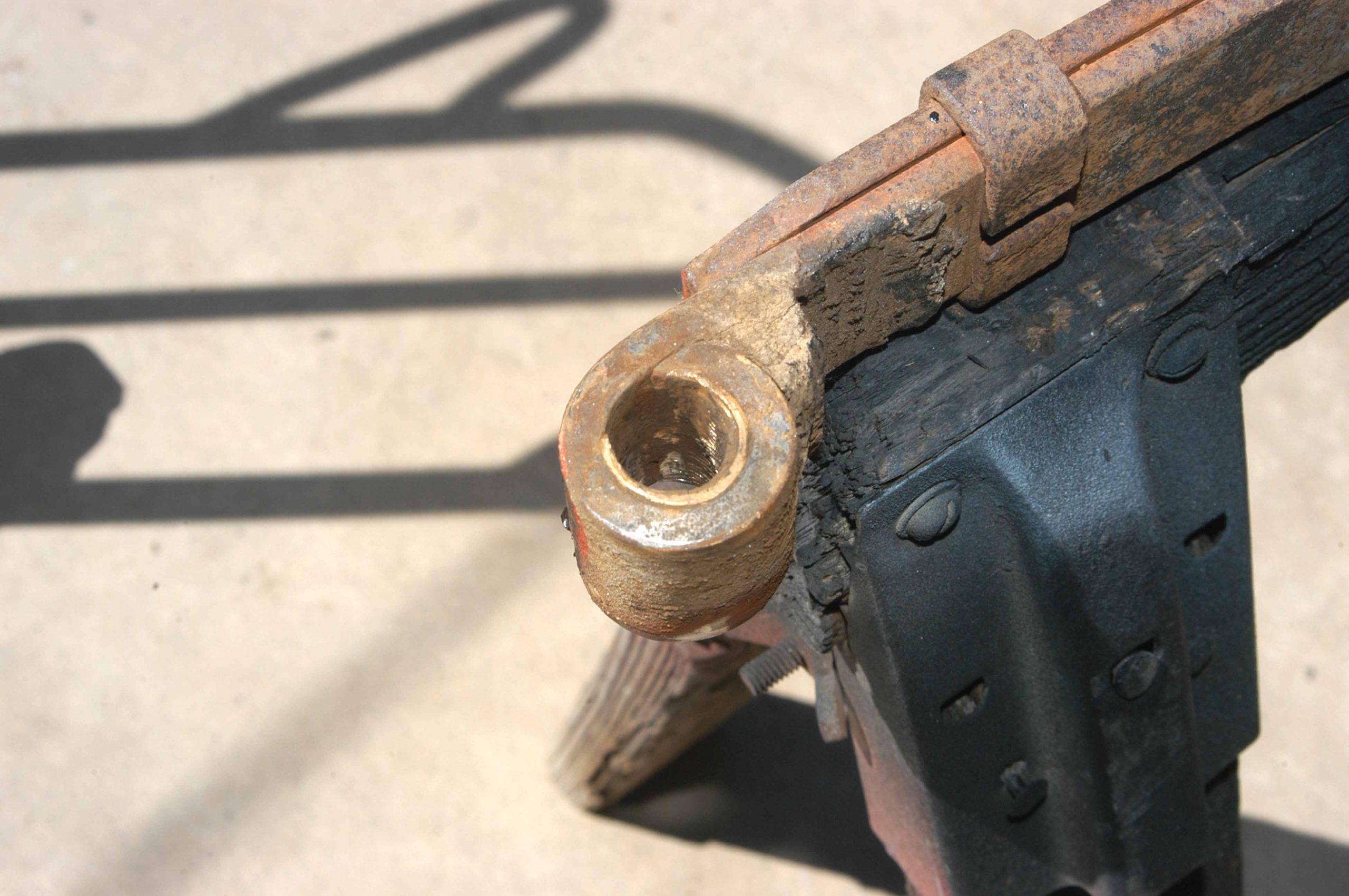
13 Here is a close look at the bushing. After 67 years of use, part of the brass bushing was worn completely through.
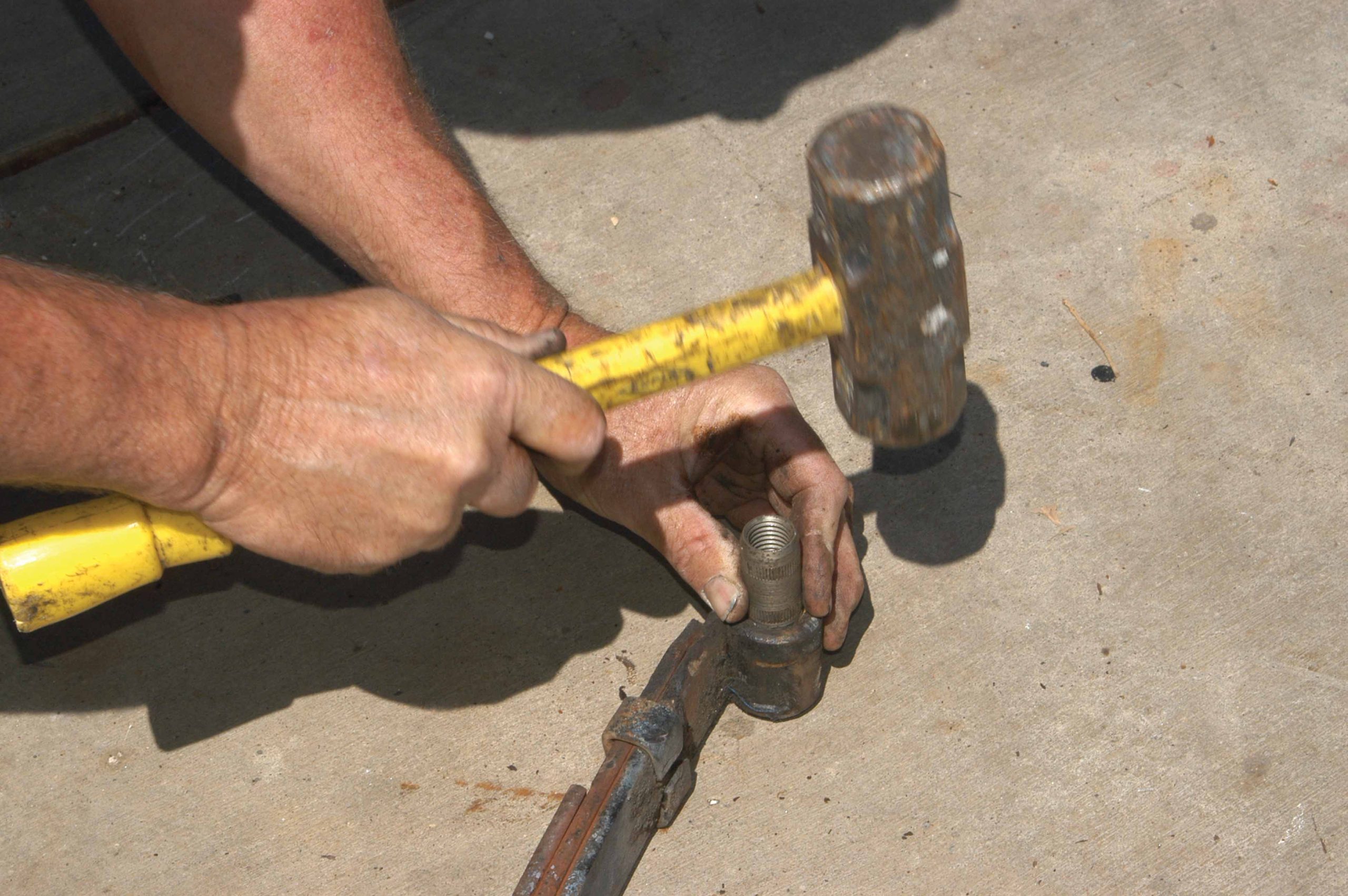
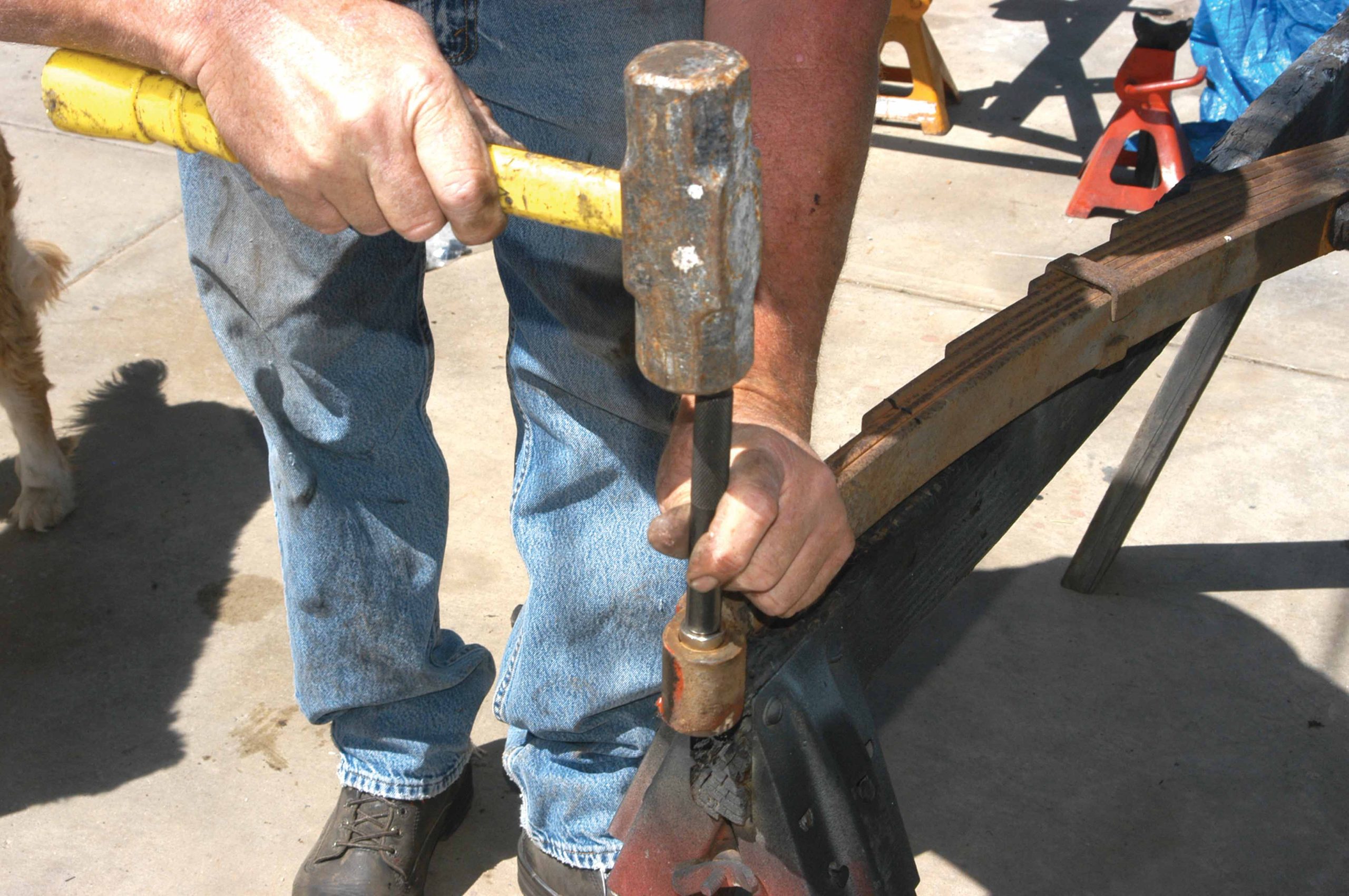
14 Using a bushing removal tool (properly sized punch), the steel insert was hammered out of the spring end.
15 The bushings and rear spring perches were replaced with new parts from Jim Carter Classic Truck Parts.
16 The metal inserts were tapped into the spring end far enough to hold them in place.
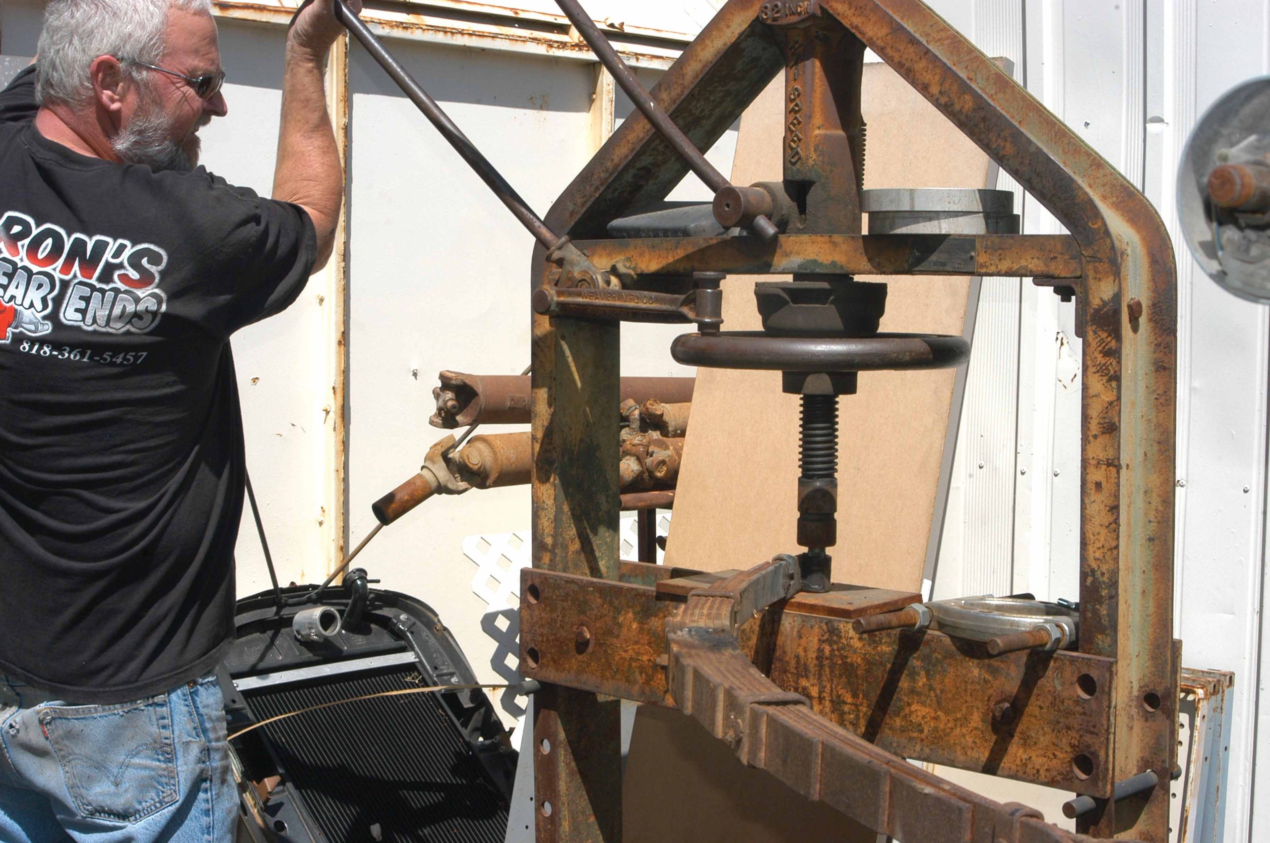
17 After the inserts were secured to the end of the spring, they were pushed the rest of the way in with a press.
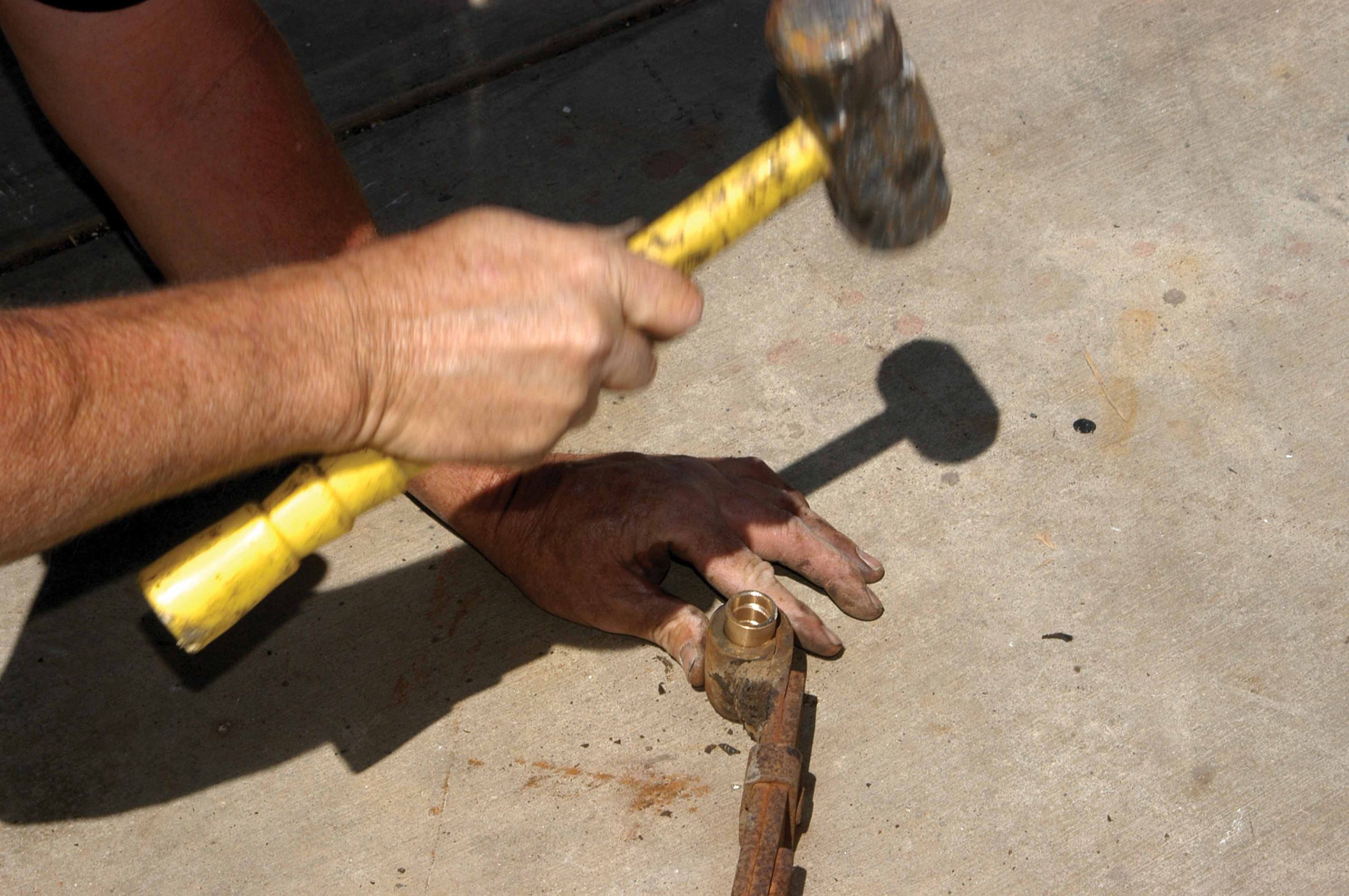
18 The brass bushings were pounded in with a hammer. They are easier to install than the steel insert-style bushing.
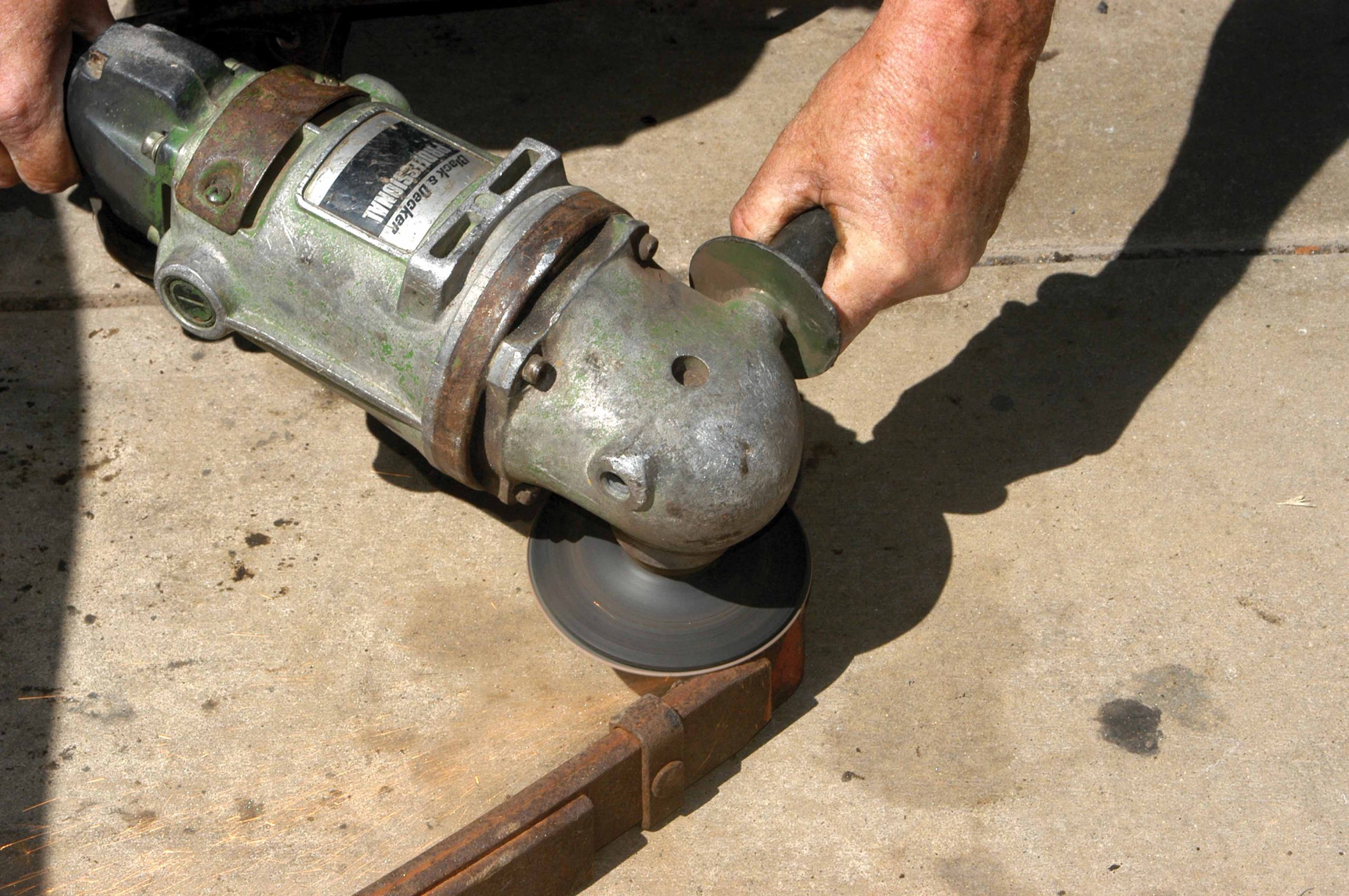
19 After the brass bushings were installed, they were sanded flat to the spring using a large hand grinder.
20 After the new brass bushings were installed, the spring was placed inside the front perch, and the bolt was installed.
21 Using an impact gun, the spring perch nut and bolt were tightened.
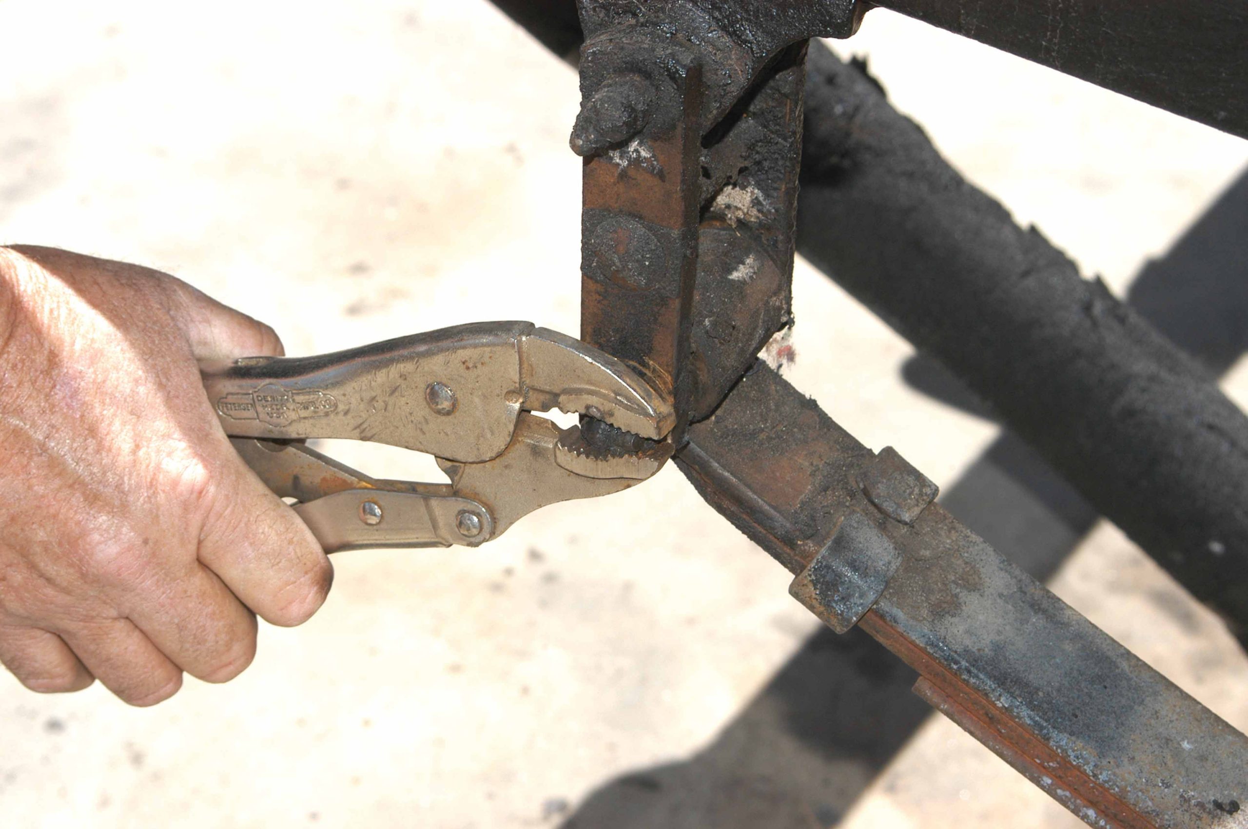
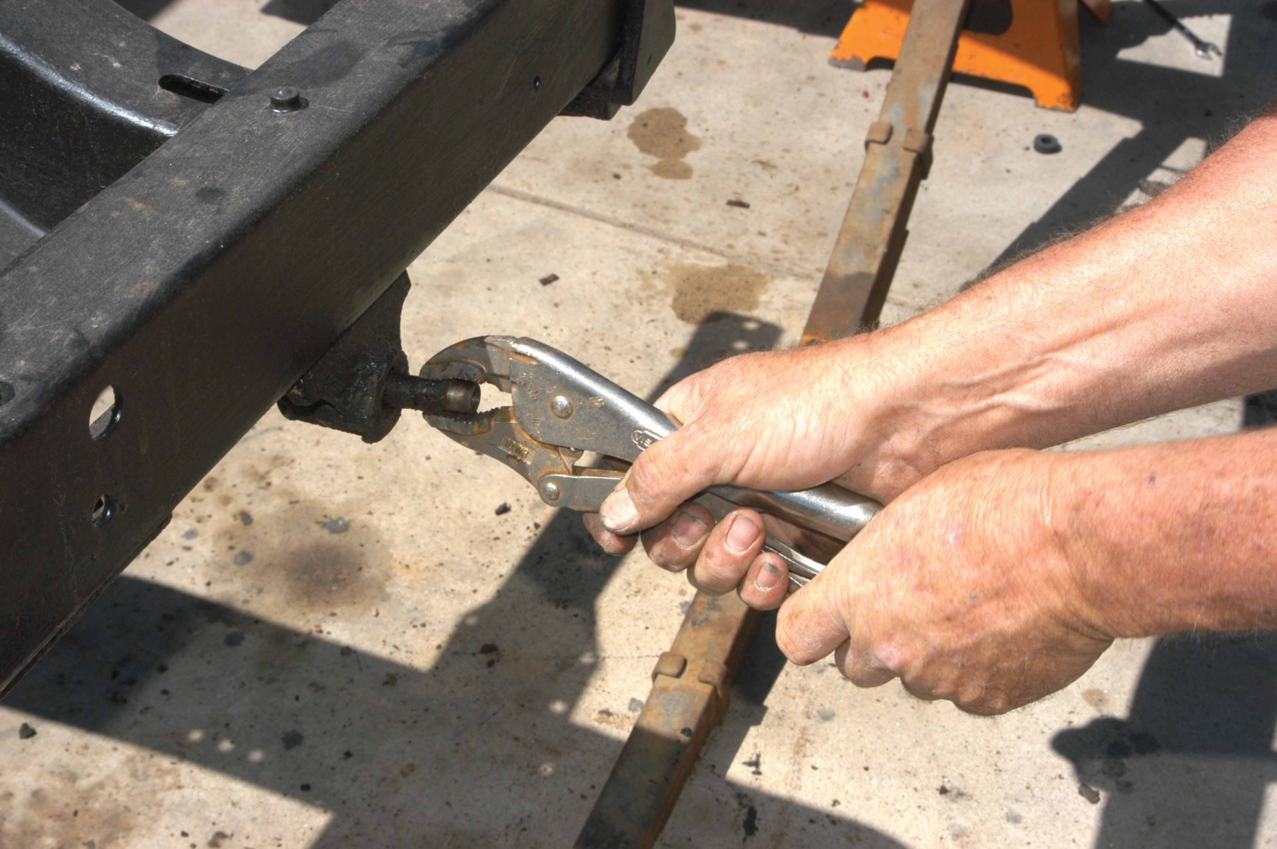
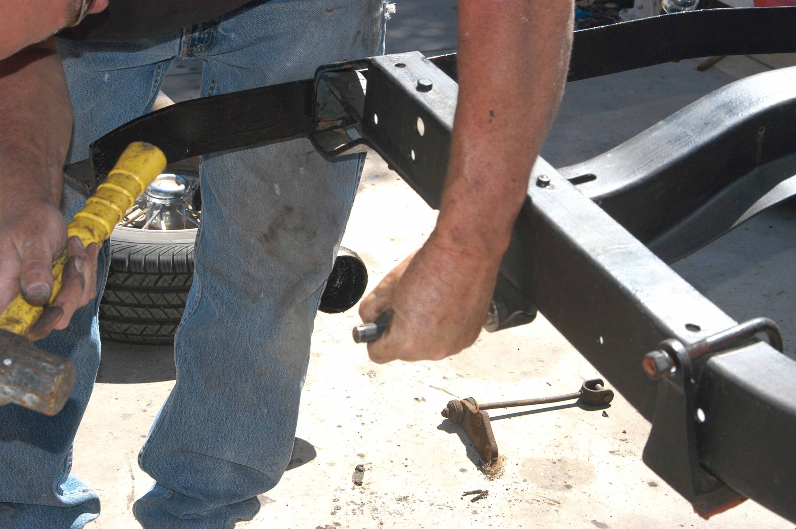
22 The rear-spring perch mount also had to be rebuilt. Here, the center shaft is being removed from the bushing with a Vise-Grip plier.
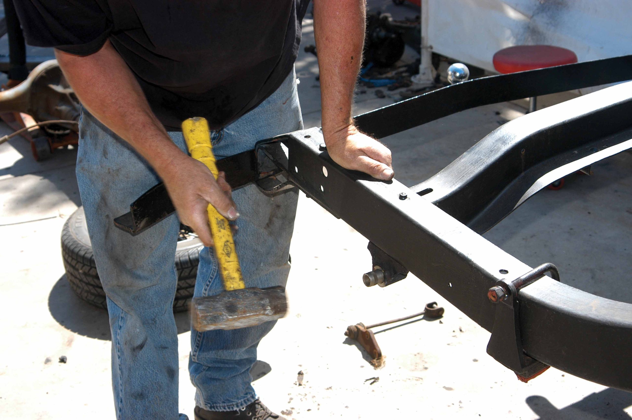
23 The bushing also had to be removed, so it was pounded out with a hammer. It went in about halfway and then it stopped.
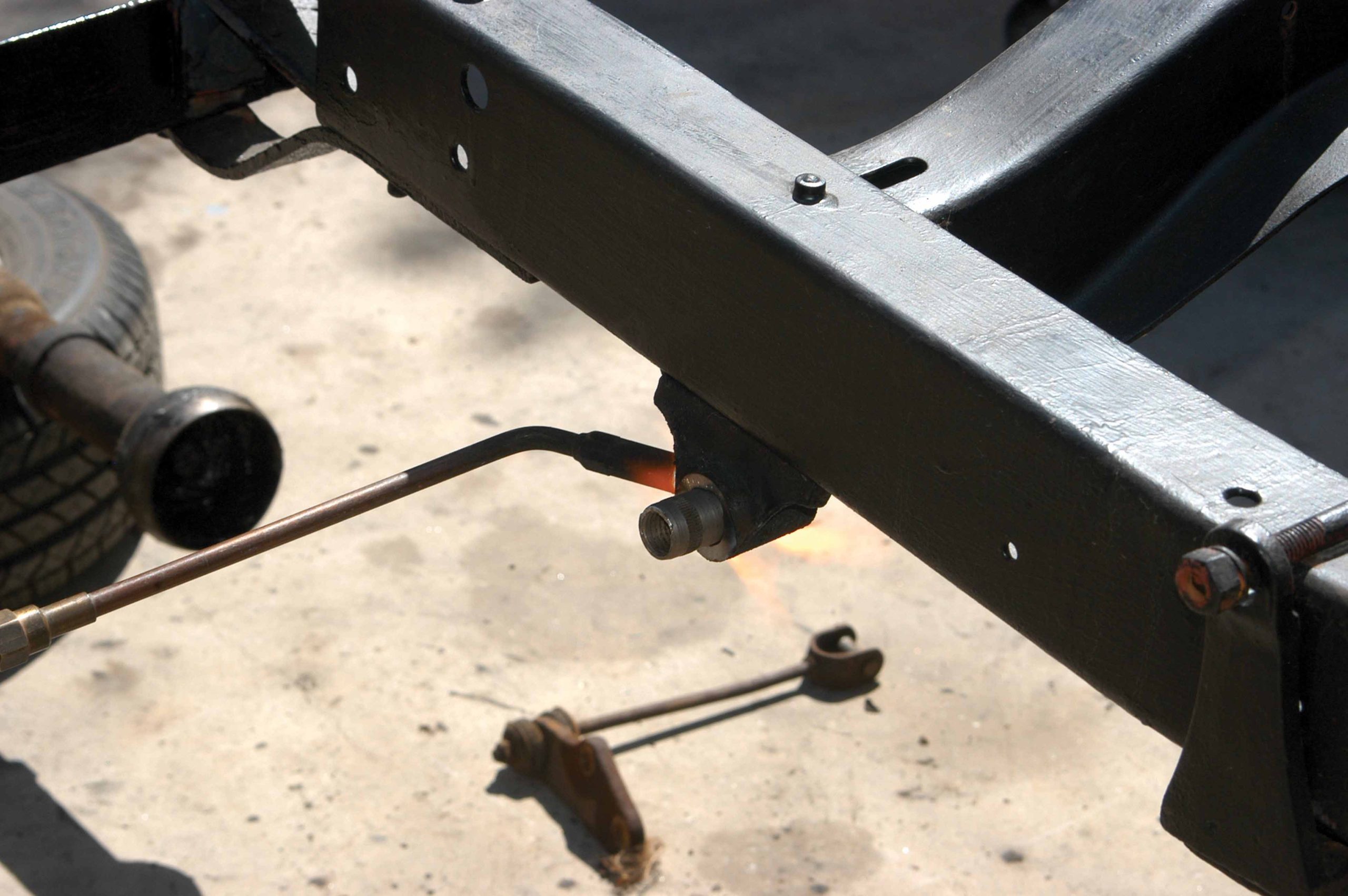
24 When the upper bushing was stuck, the mount was heated up with a rosebud tip on an oxy-acetylene torch.
25 With the spring mount heated, the bushing was hammered the rest of the way out.
26 The new insert was installed partway with a large hammer.
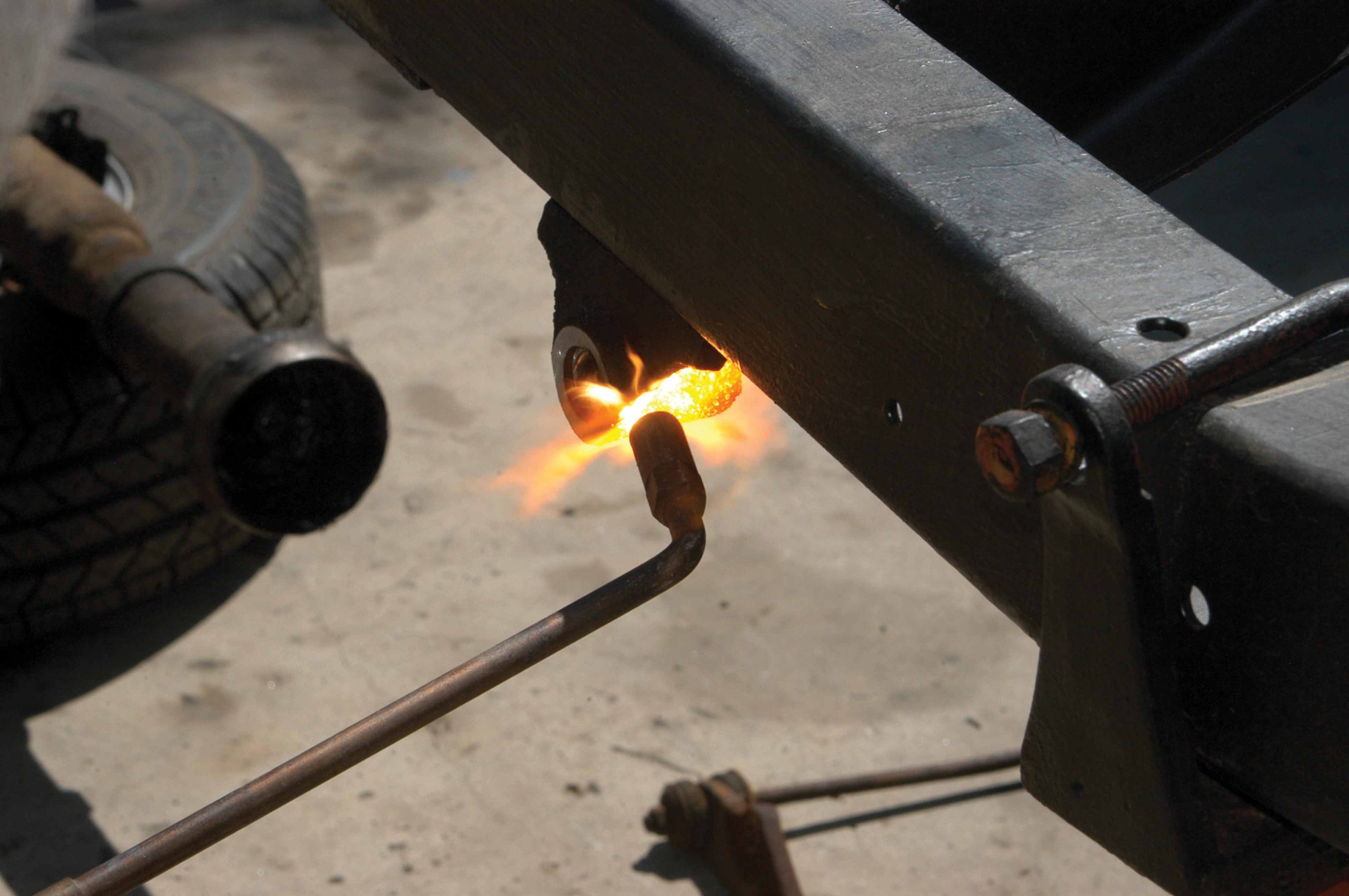
27 The mount was heated up again until it was red hot to make it easier to install the insert.
28 After the mount was heated, the insert was easier to install.
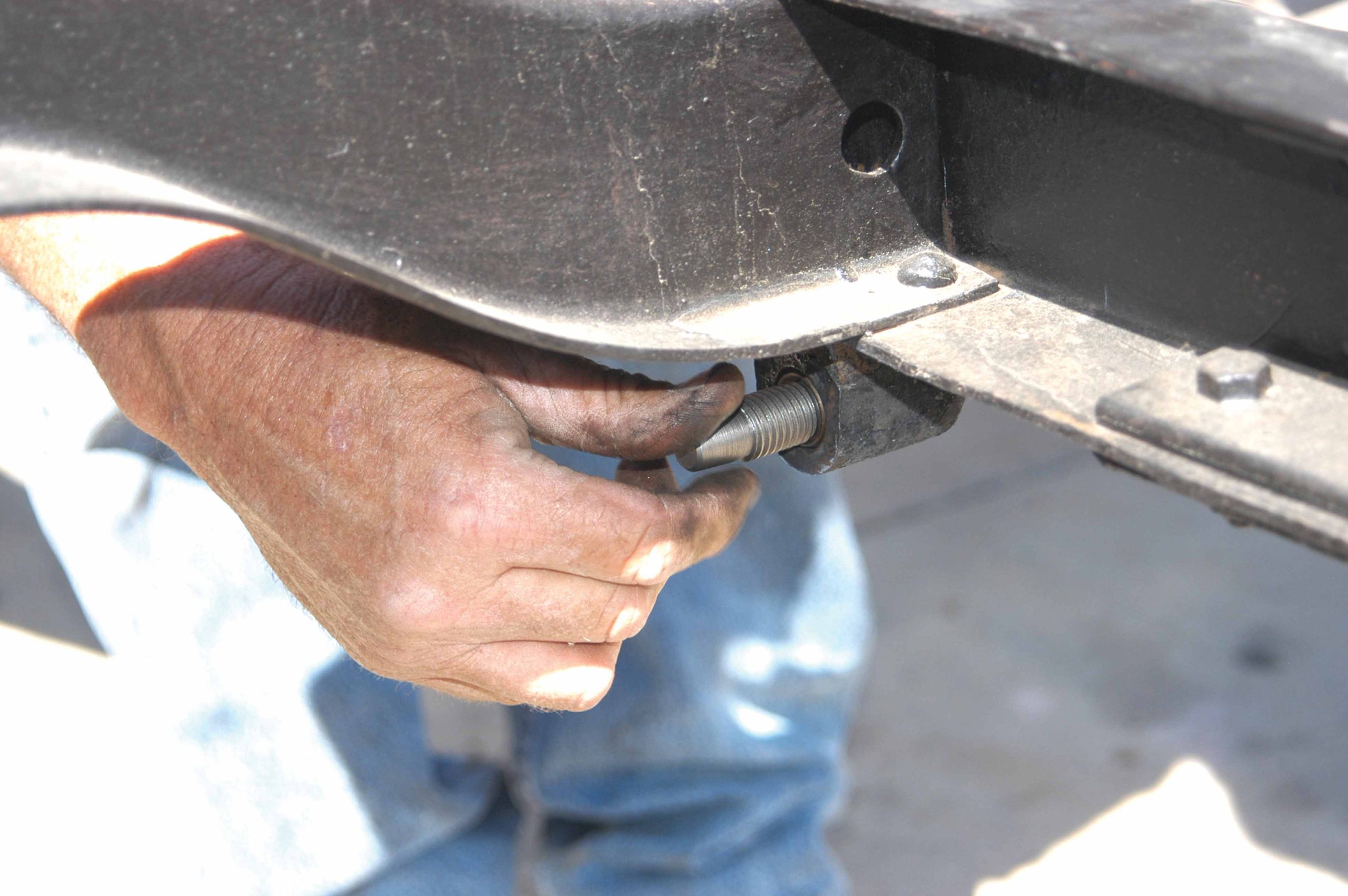
29 The new bushing is designed for a screw-in shaft and here it is being installed in the frame mount.
30 The Camaro 10-bolt differential was placed on a floor jack then rolled under the frame.
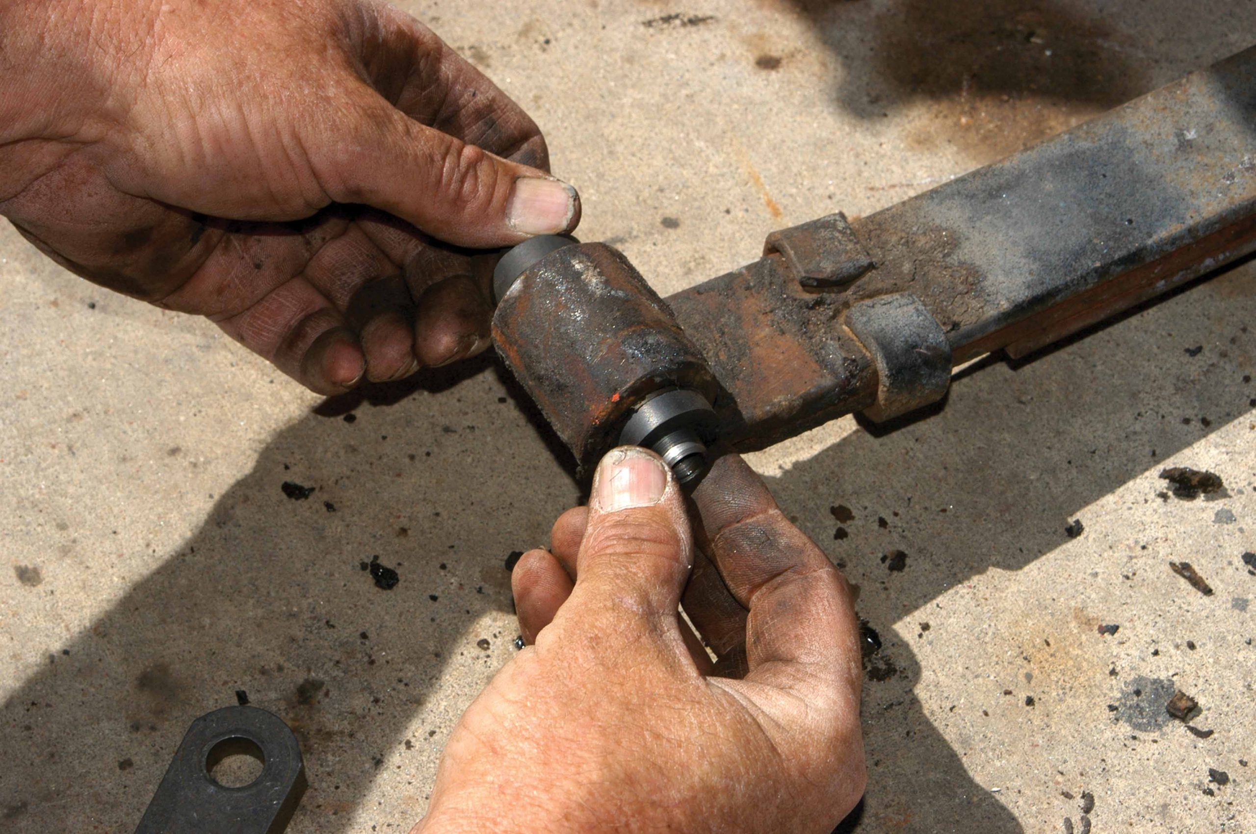
31 After the screw-in shaft was installed, the rubber seals were installed on the ends.
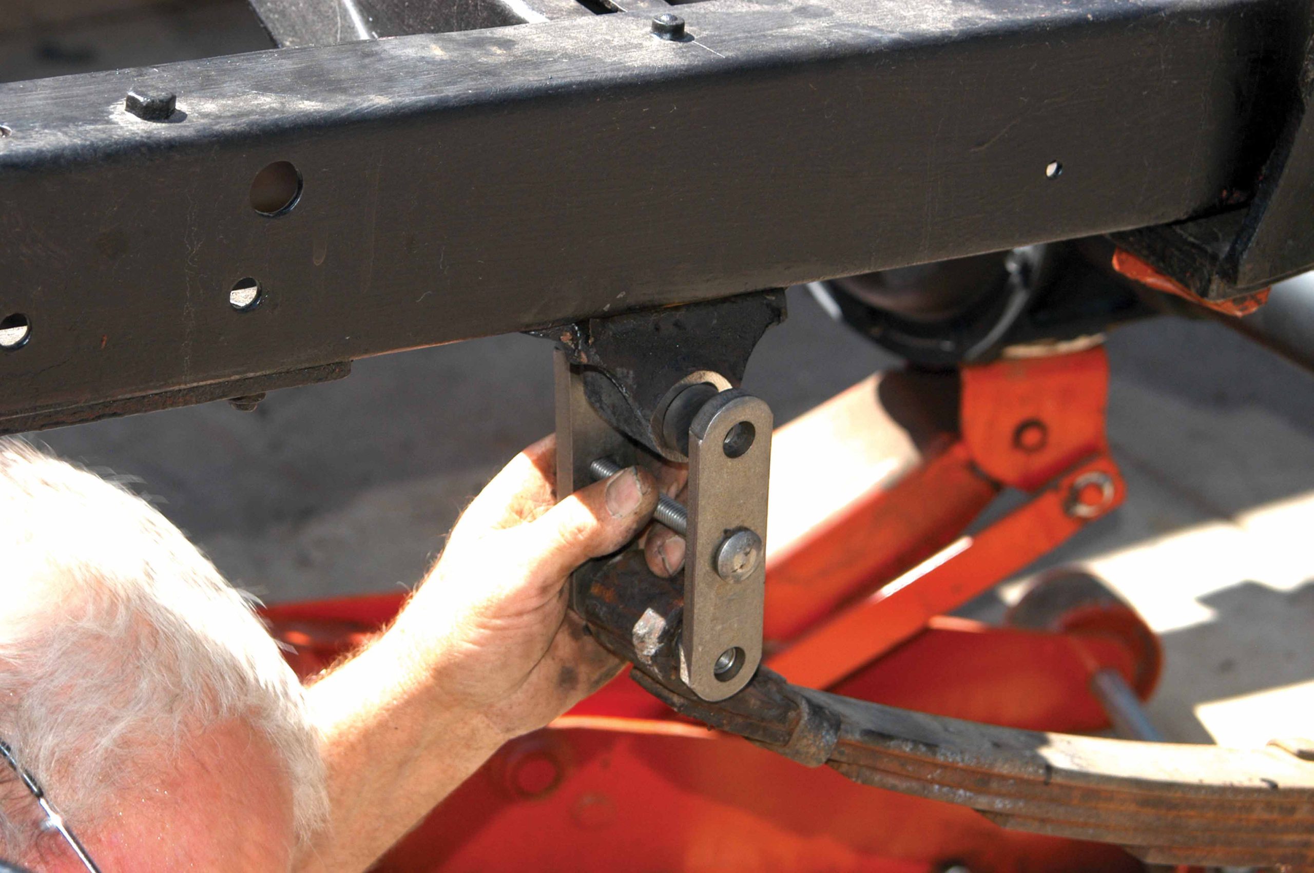
32 The new shackle bars were installed on the shaft ends, and then the center bolt was installed.
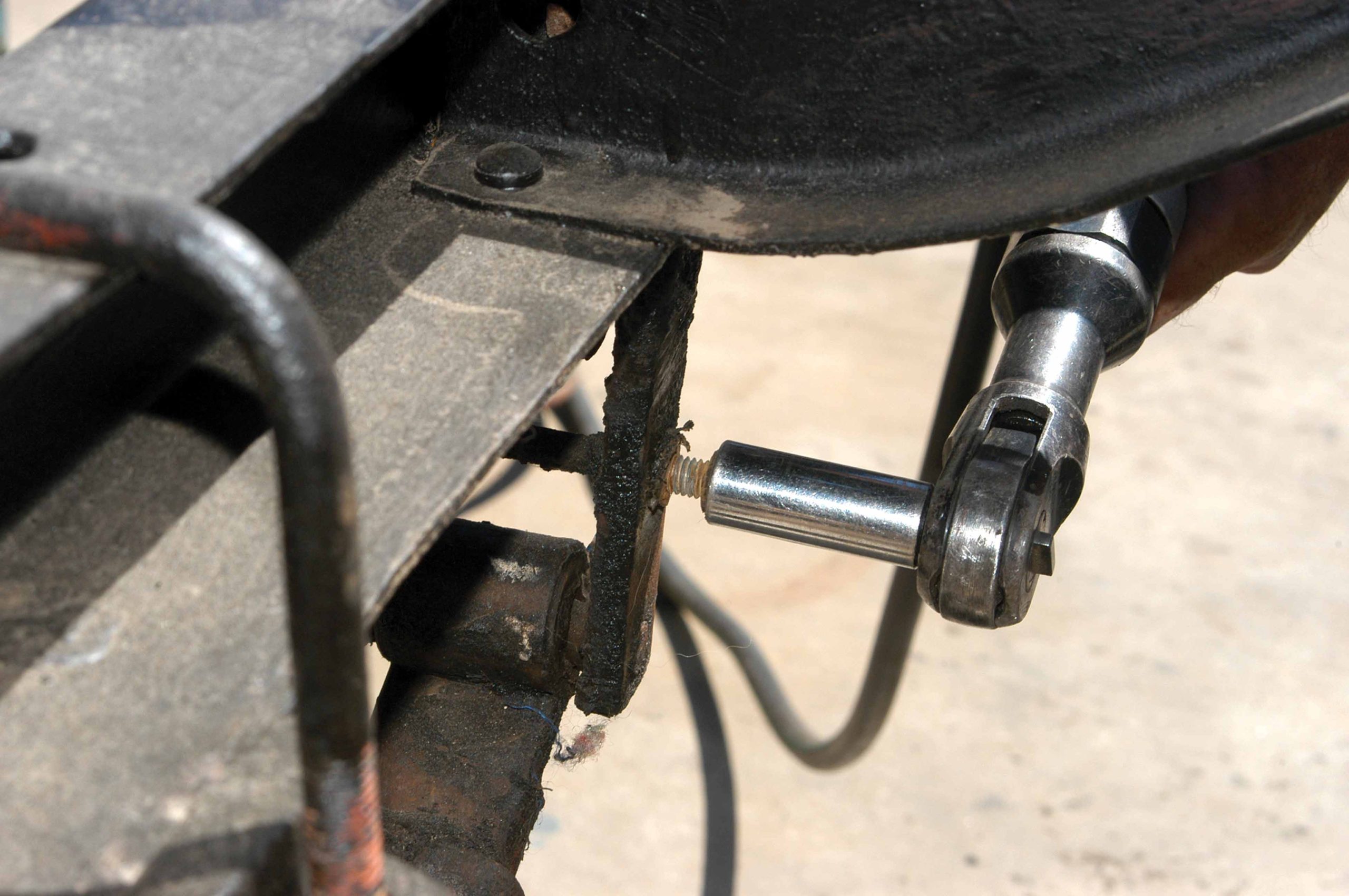
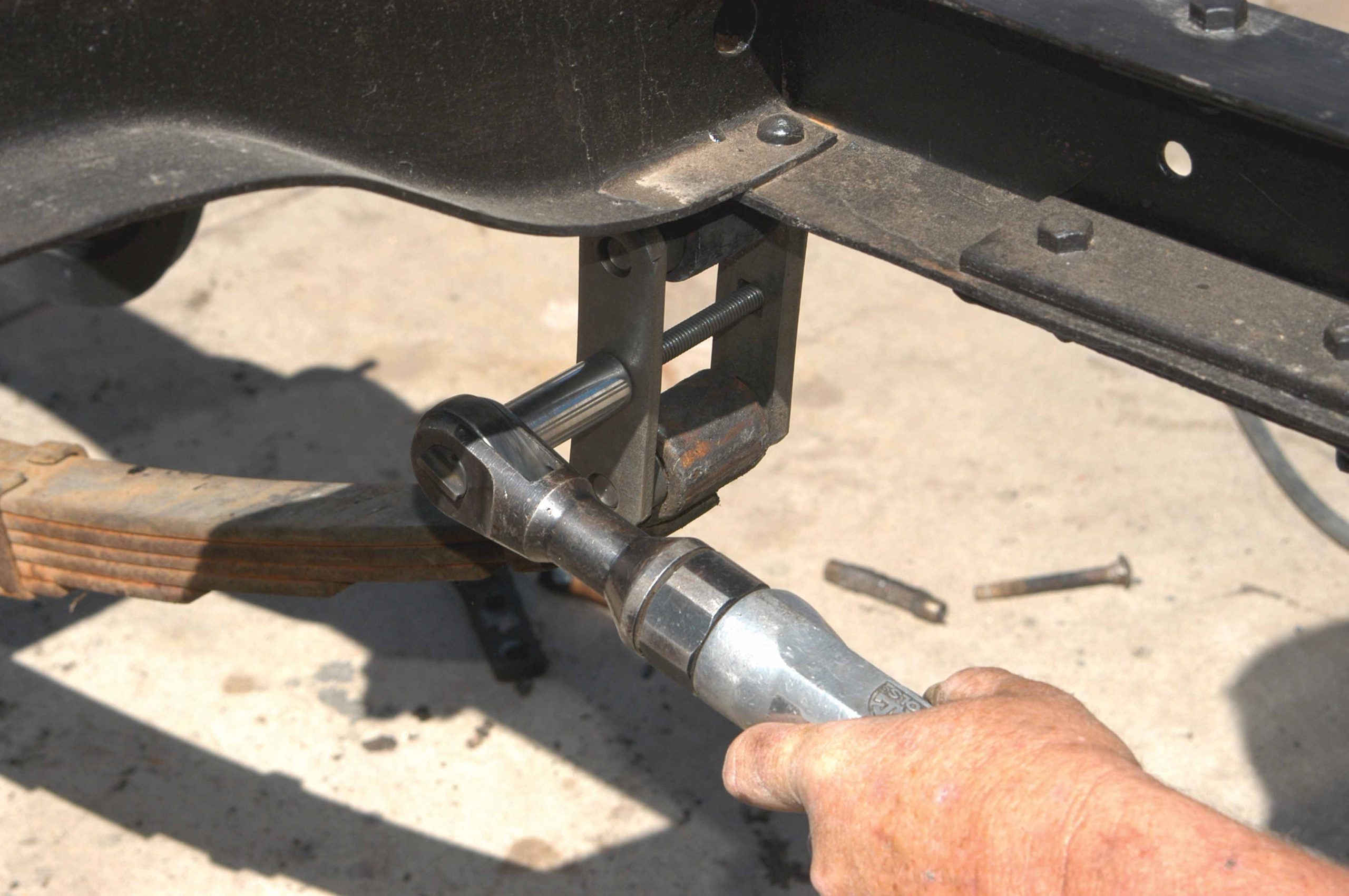
33 The shackle bars were secured with an air ratchet and a 9/16-inch socket.
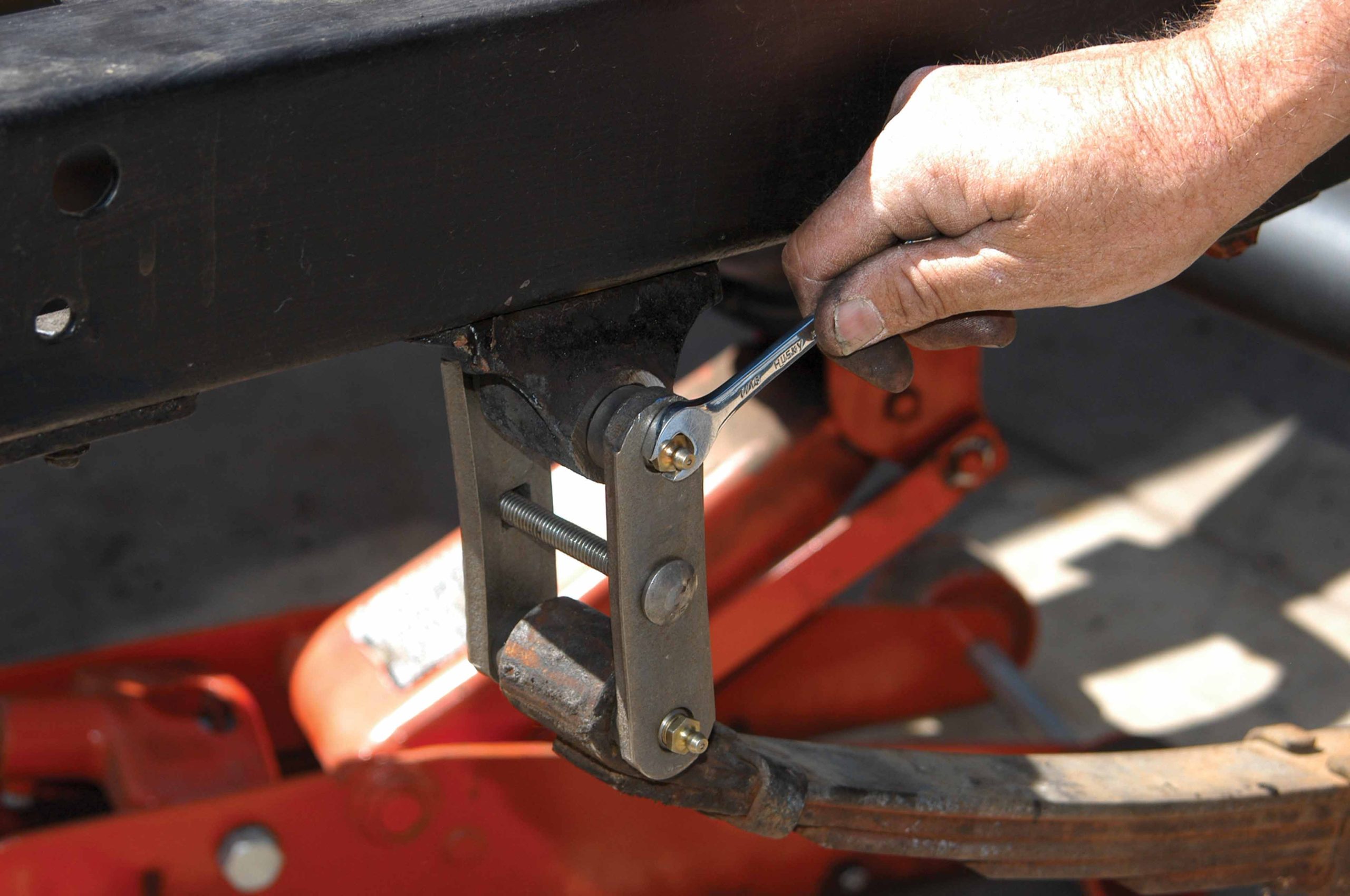
34 After the shackles were installed, grease fittings were installed in the shafts. This kit was delivered with new grease fittings.
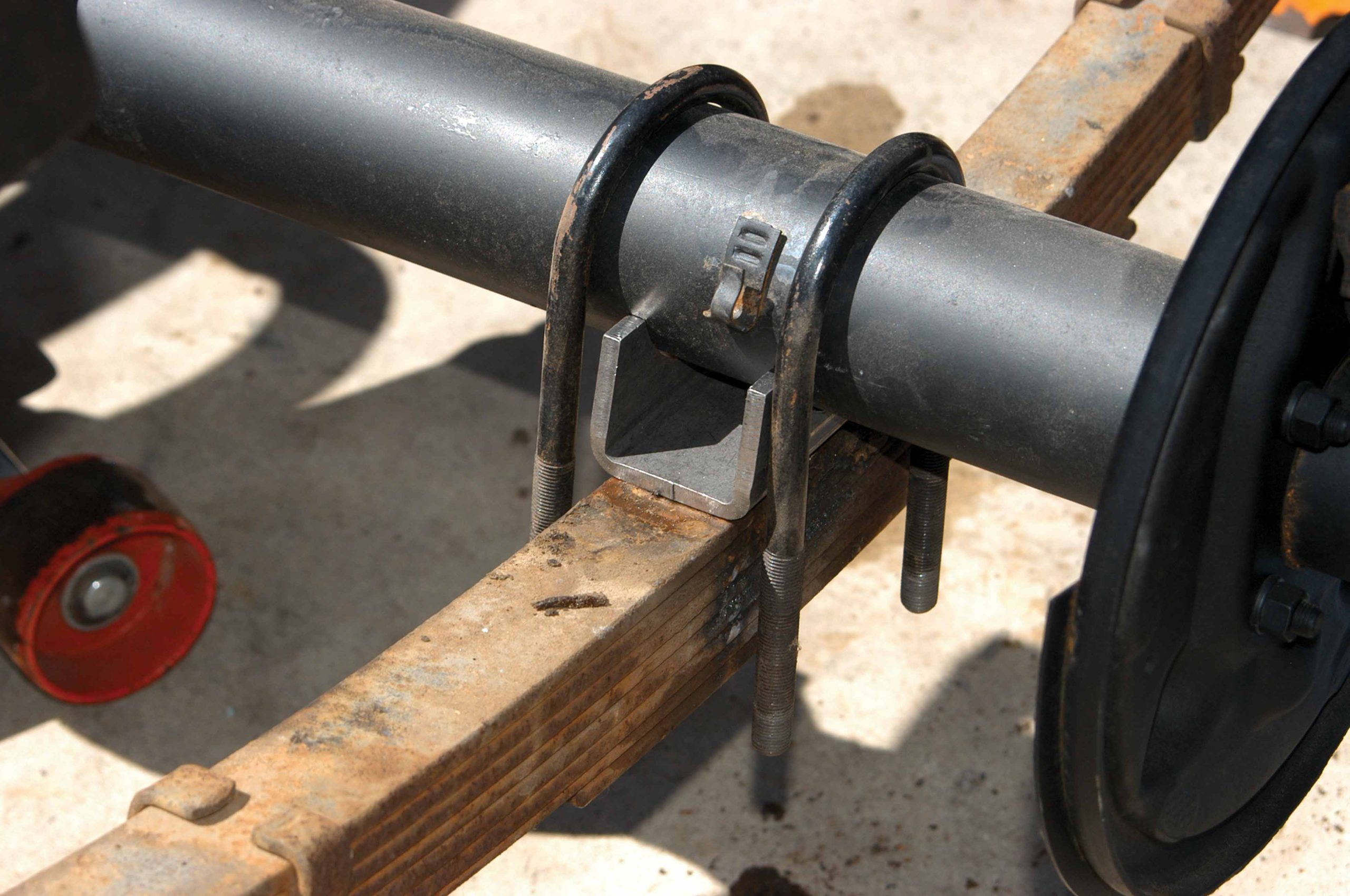
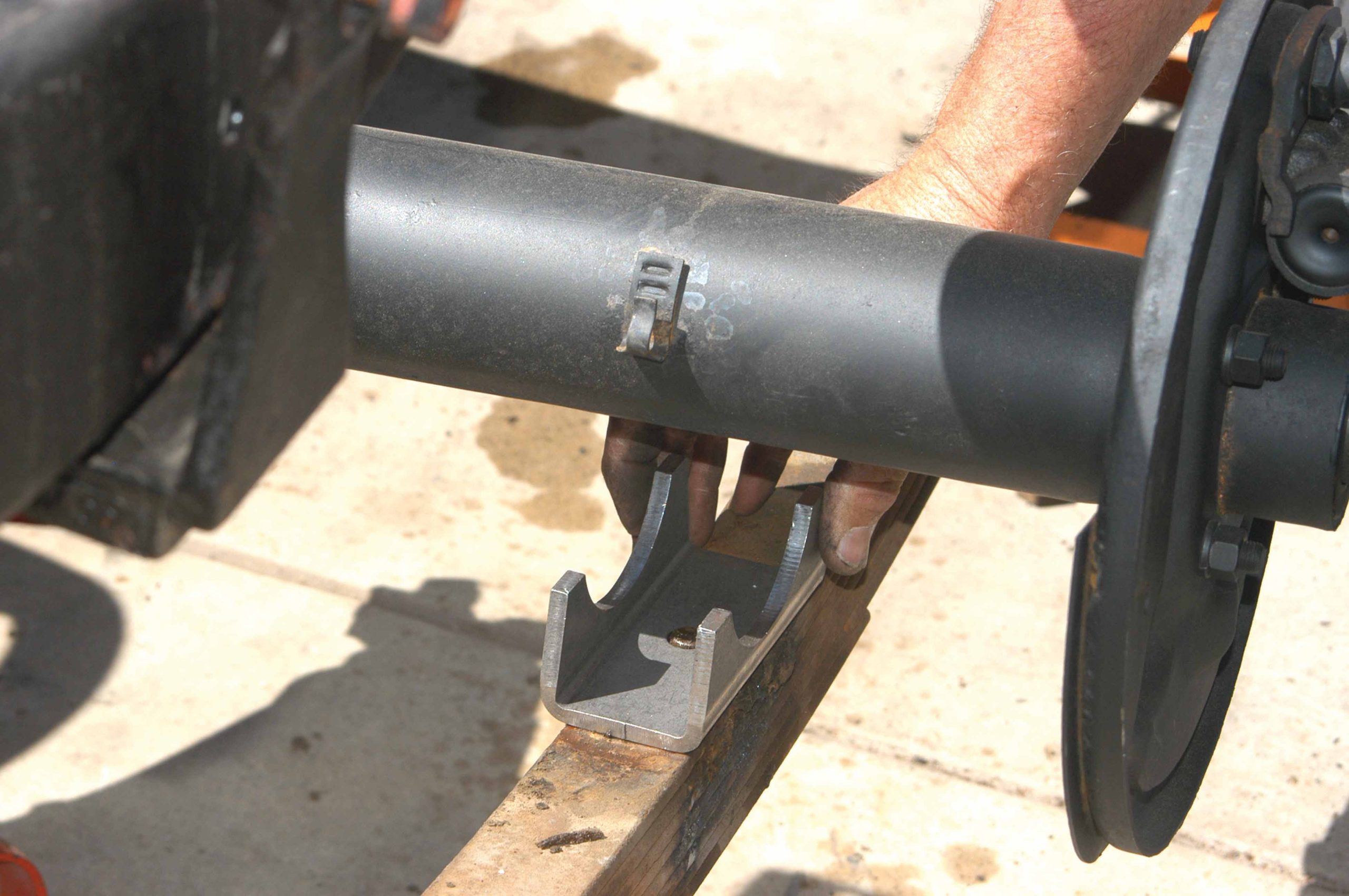
35 The aftermarket spring pads were placed over the center bolts in the springs.
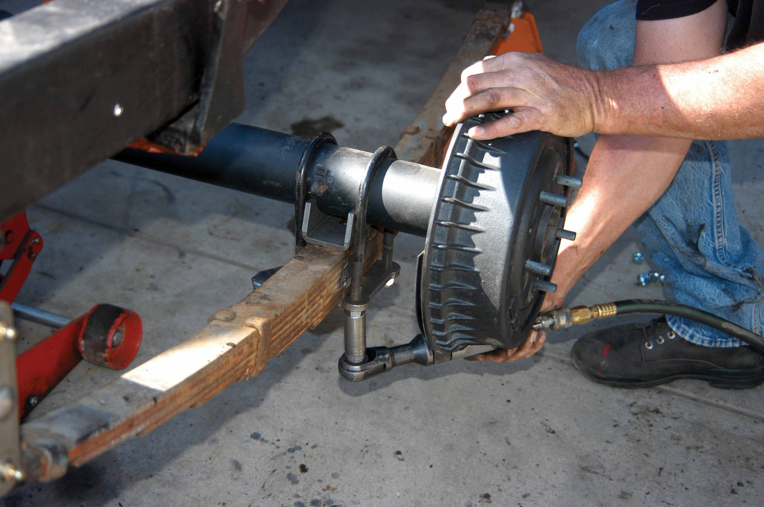
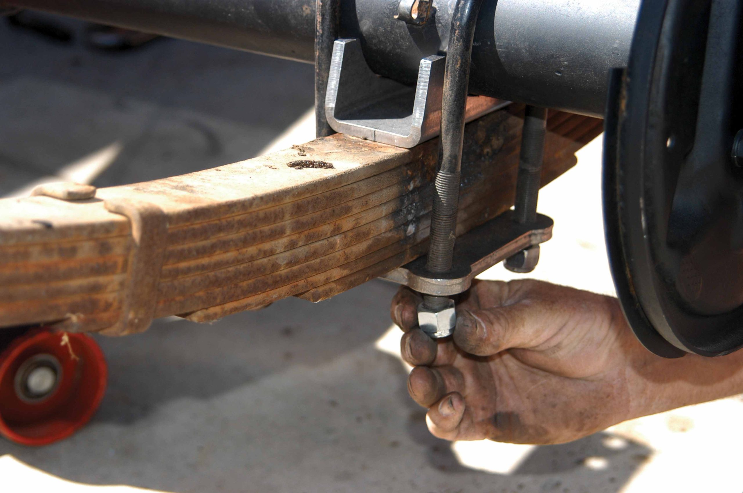
36 The differential was lowered onto the spring pads, and then the U-bolts were positioned over the axle tubes.
37 The spring plate/shock mount was installed next, and then it was tightened finger-tight with four lock nuts.
38 After the plate was secure, the special shock bolt was installed next.
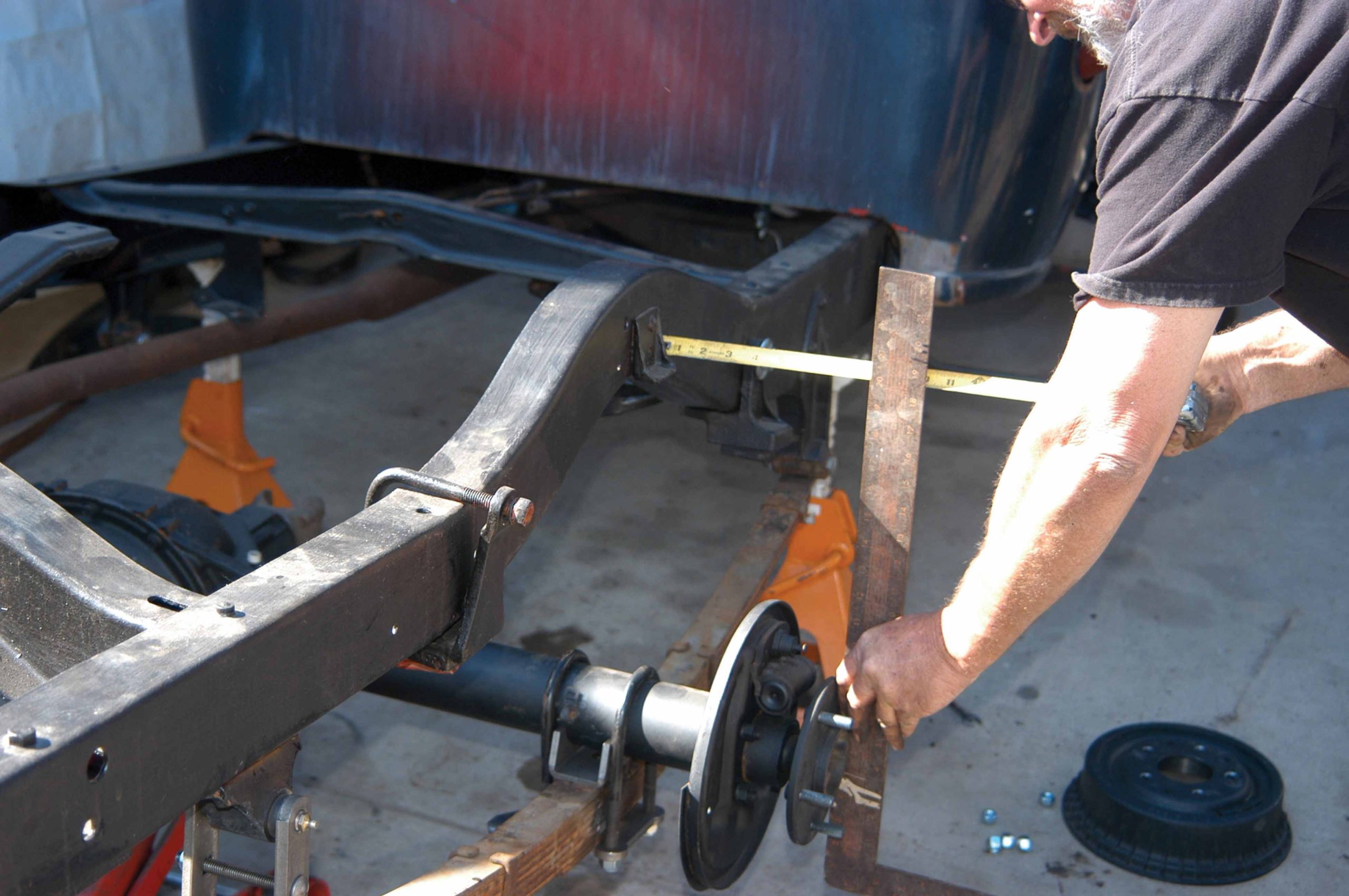
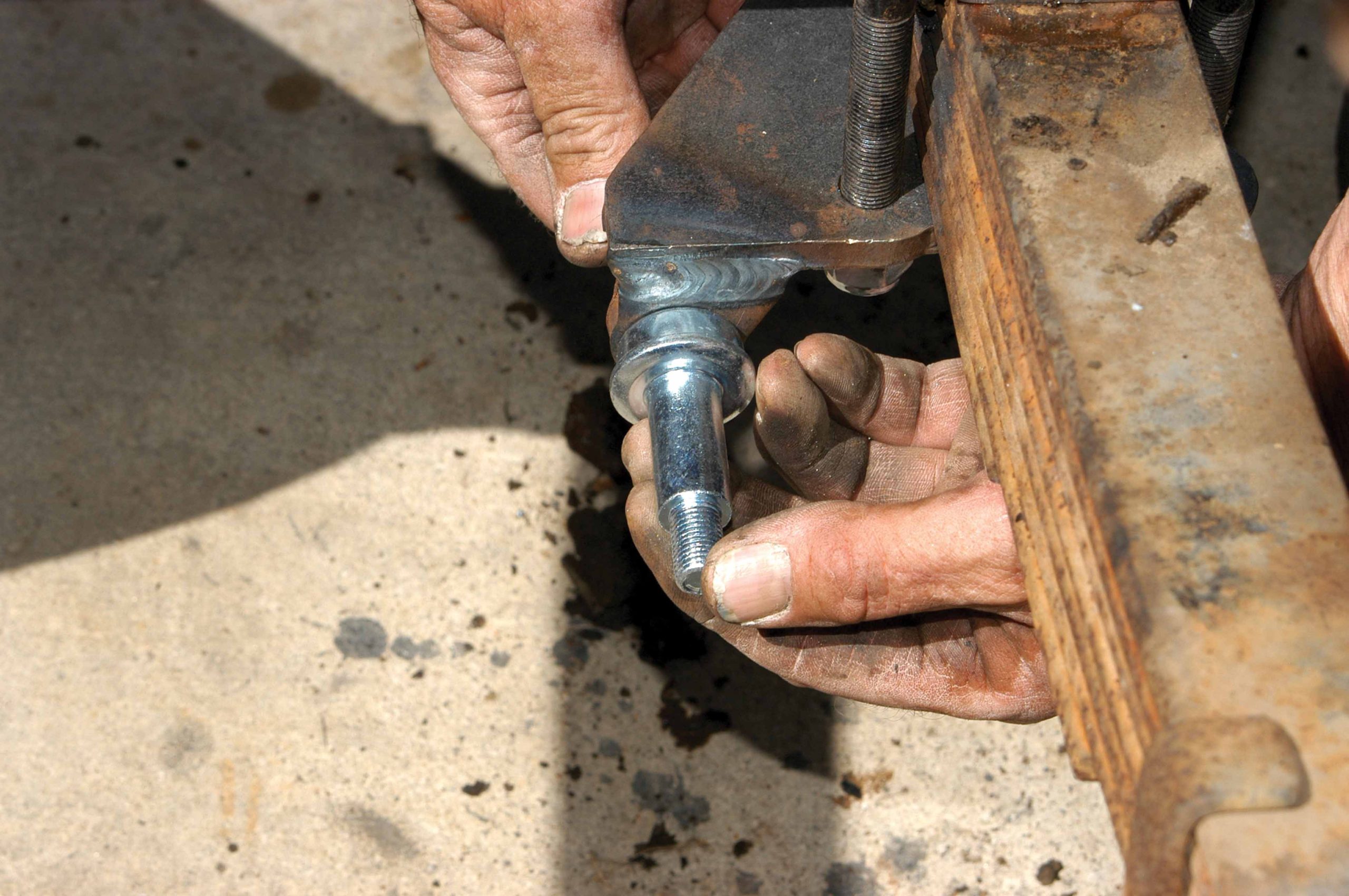
39 Using a large L-square and a tape measure, the differential was centered under the frame.
40 After the differential was centrally located, the U-bolt nuts were tightened but were kept loose enough to enable the differential angle to be set.
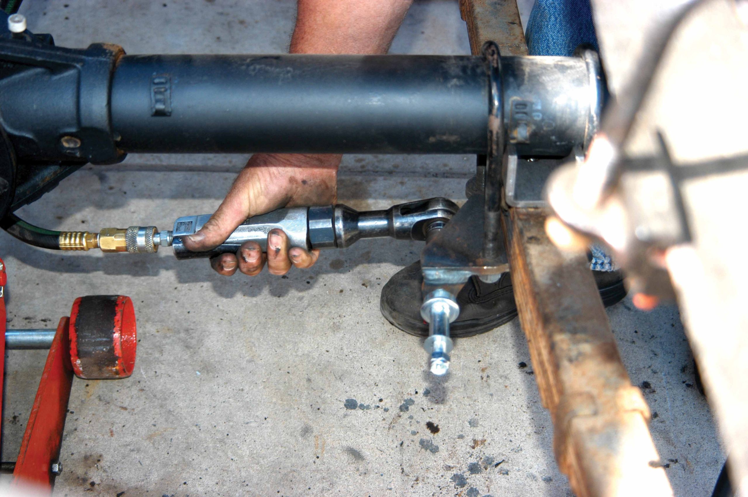
41 The shock bolt was tightened with an air ratchet.
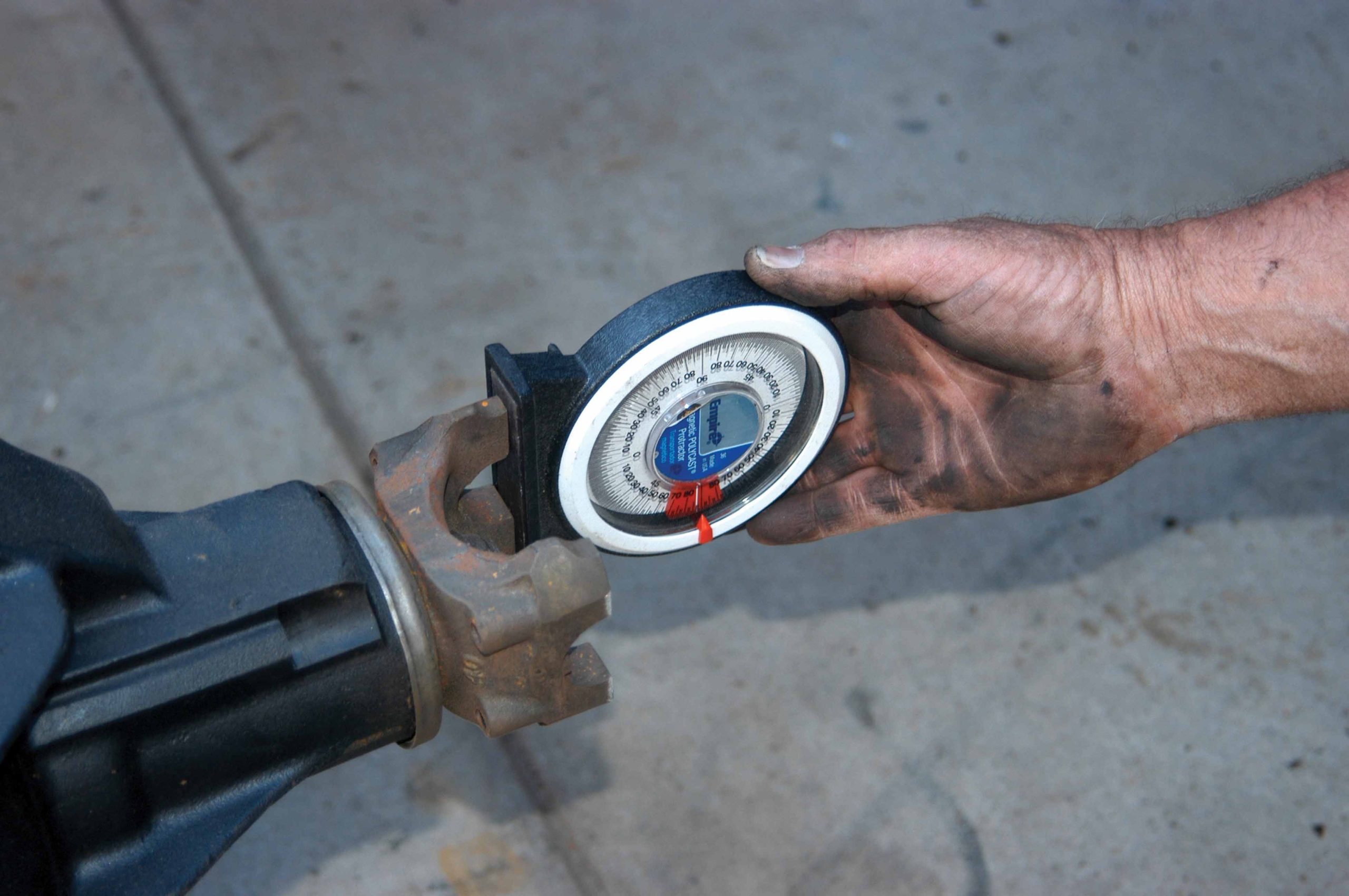
42 Using an angle finder, the angle of the differential was set properly.
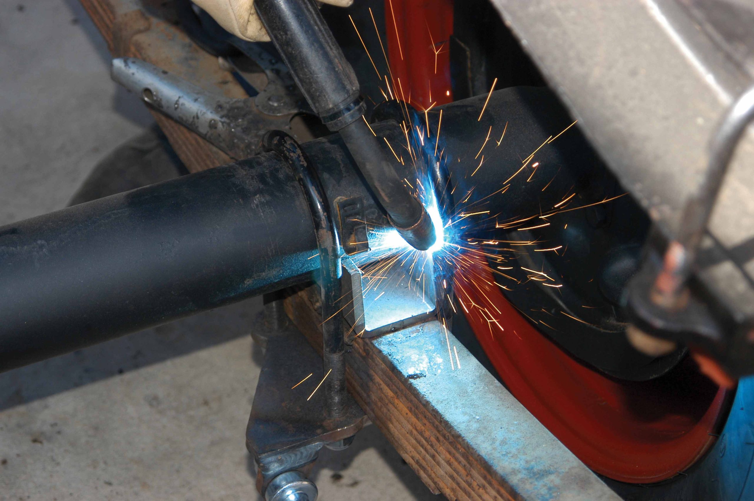
43 After the differential was centered and sitting at the correct angle, the aftermarket spring pads were tack-welded to the axle housing. After they were secure, the U-bolts were removed and the pads were finish-welded to the axle.
44 The shock absorber was installed over the shock bolt and then secured.
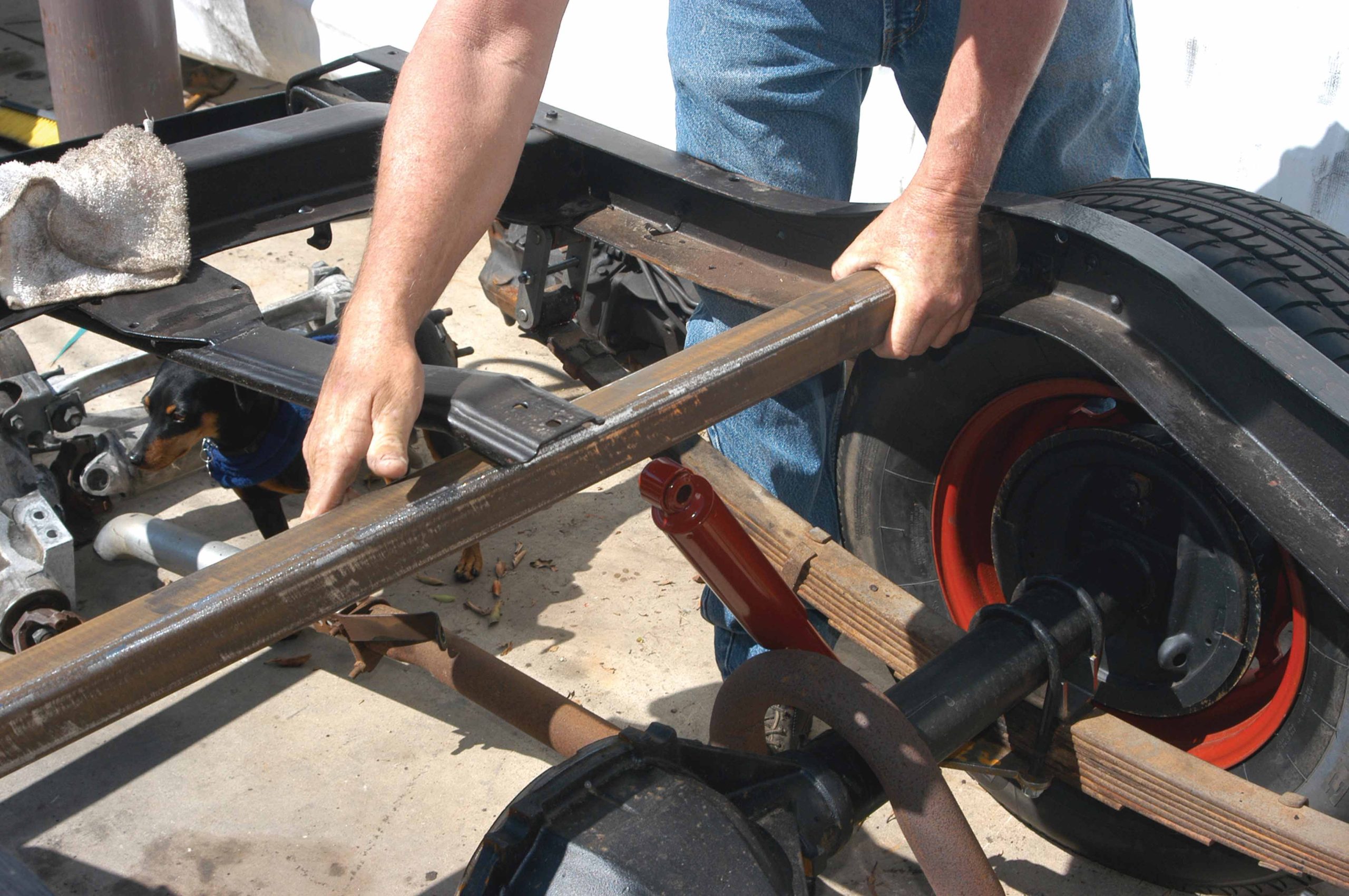
45 The upper shock mount had to be fabricated, so a large section of square tubing was cut the width of the inside frame, placed between the frame and moved forward.
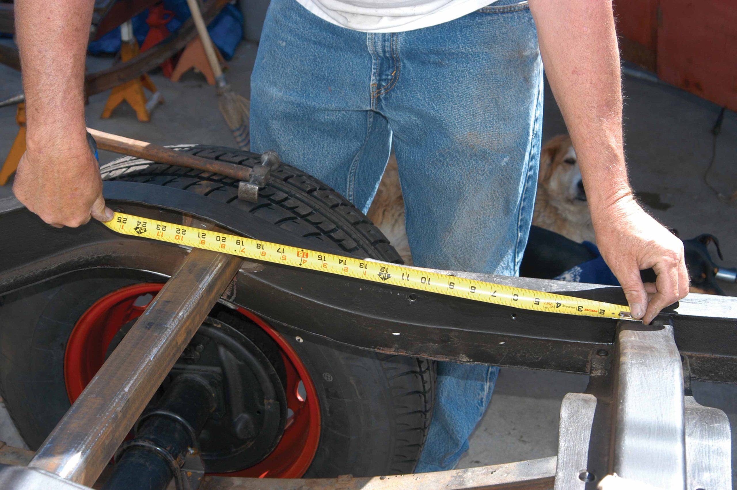
46 After the square tubing was in line with the shocks, measurements were made to make sure both sides were sitting evenly.
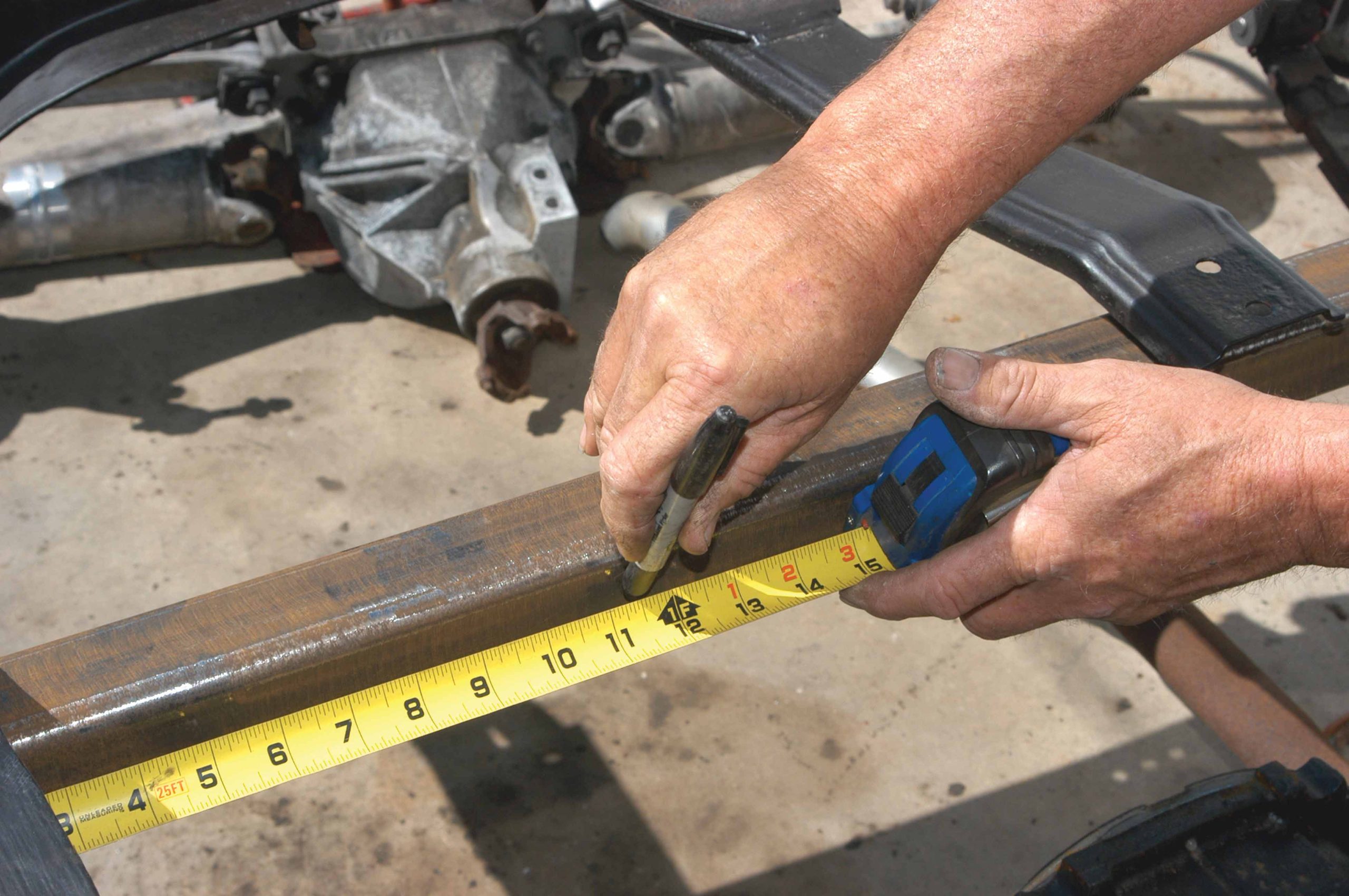
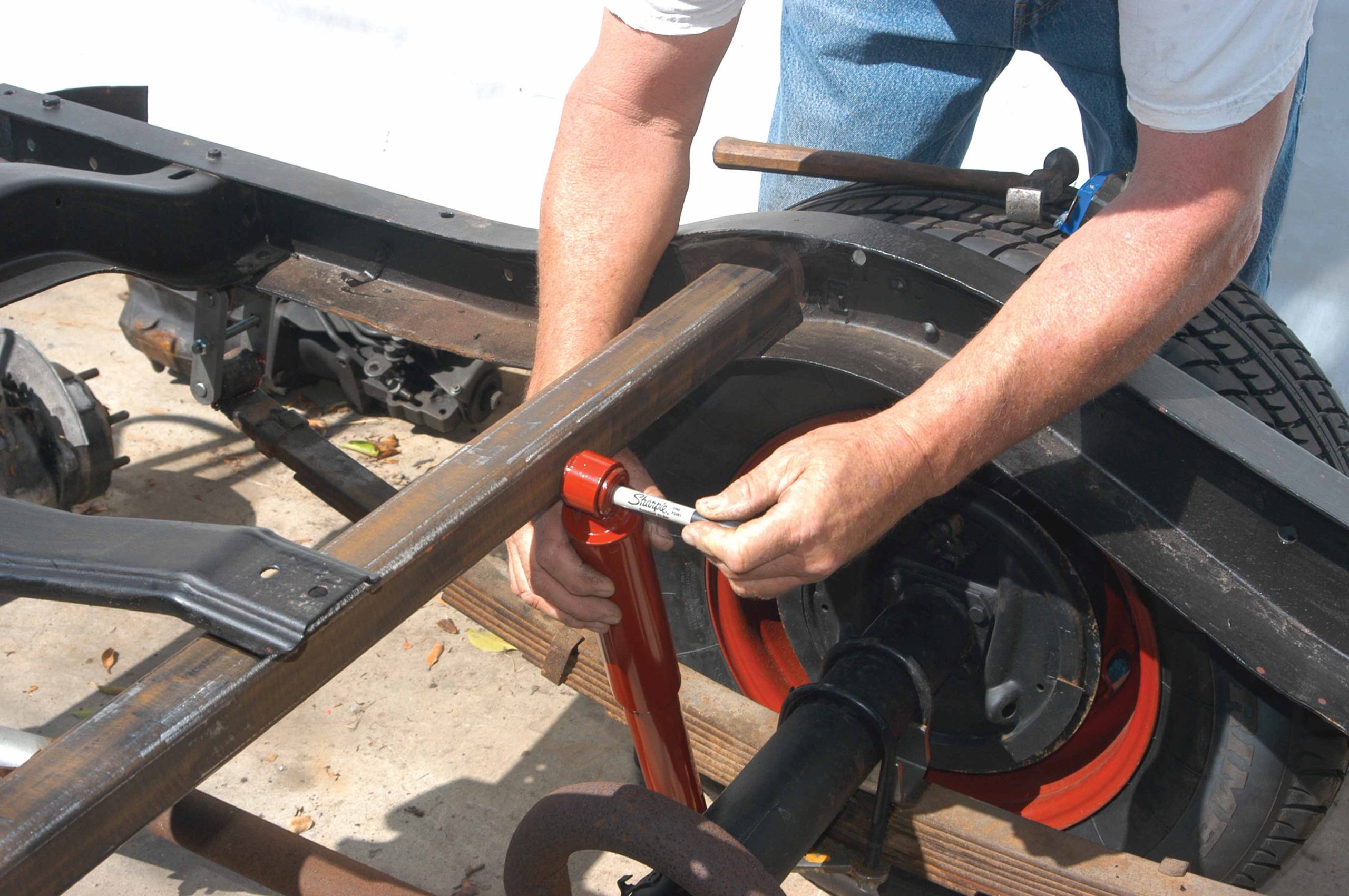
47 The shock was held up against the square tubing and a mark was made where the shock should be secured. Here, the mark is being made with a black felt pen.
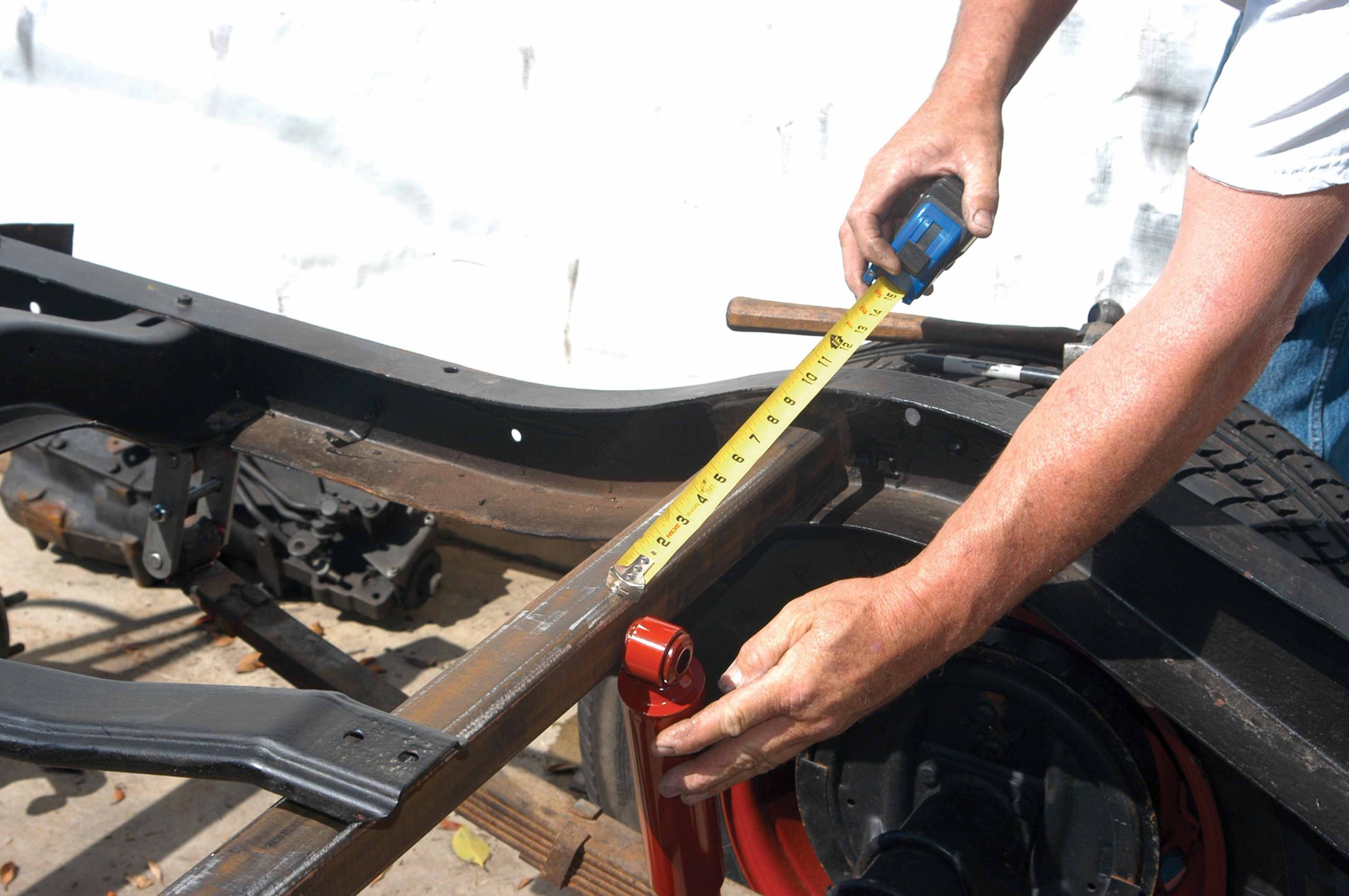
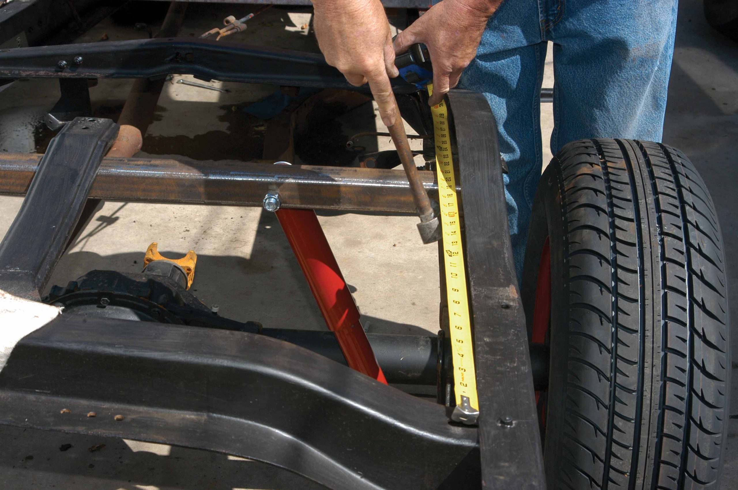
48 The distance from the shock to the frame was measured, so that the shock on the other side can be installed to match.
49 Using the measurement that was just made, the shock location was marked on the square tubing with a black felt pen.
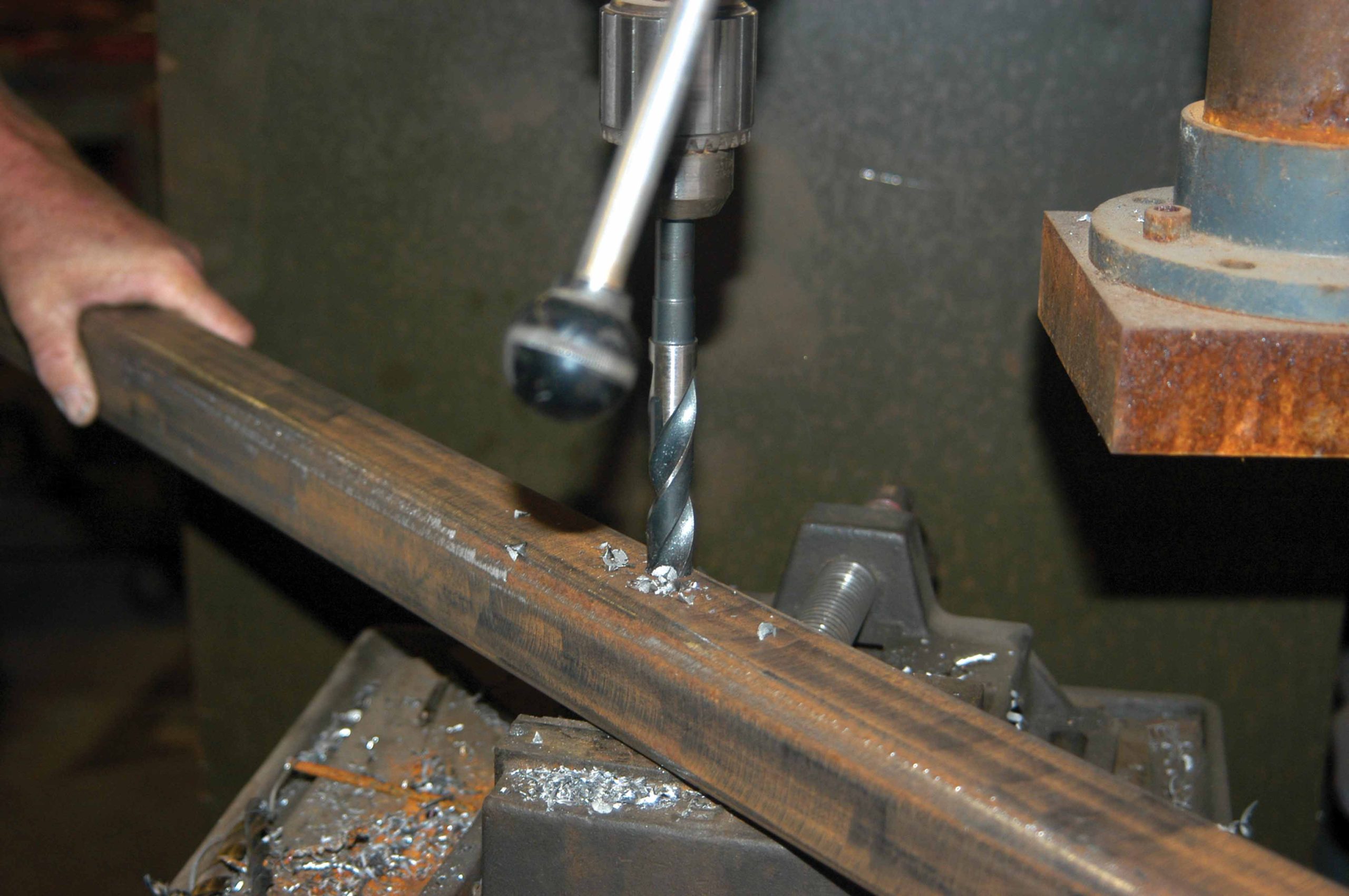
50 The square tubing was removed from the frame and the tubing was drilled for the upper shock bolts.
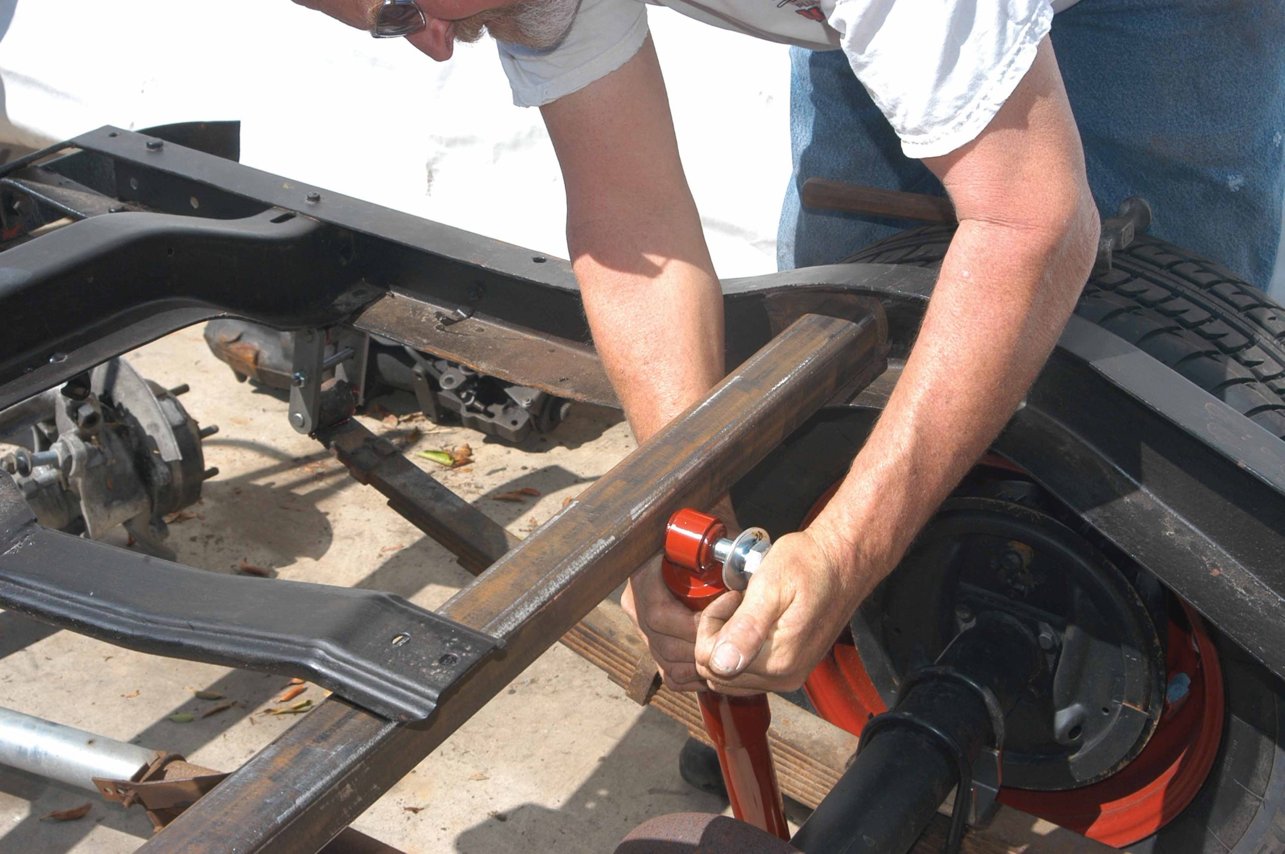
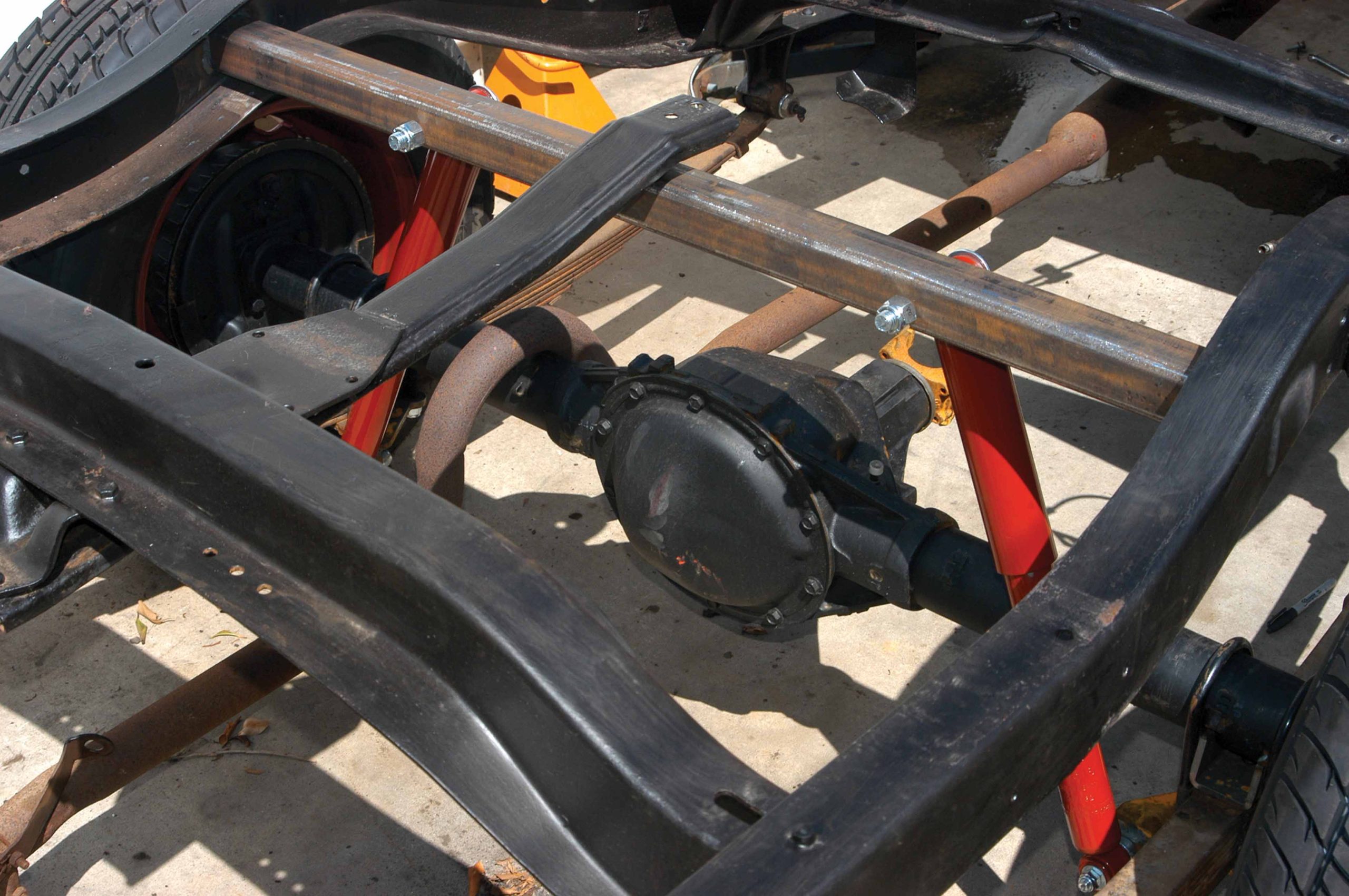
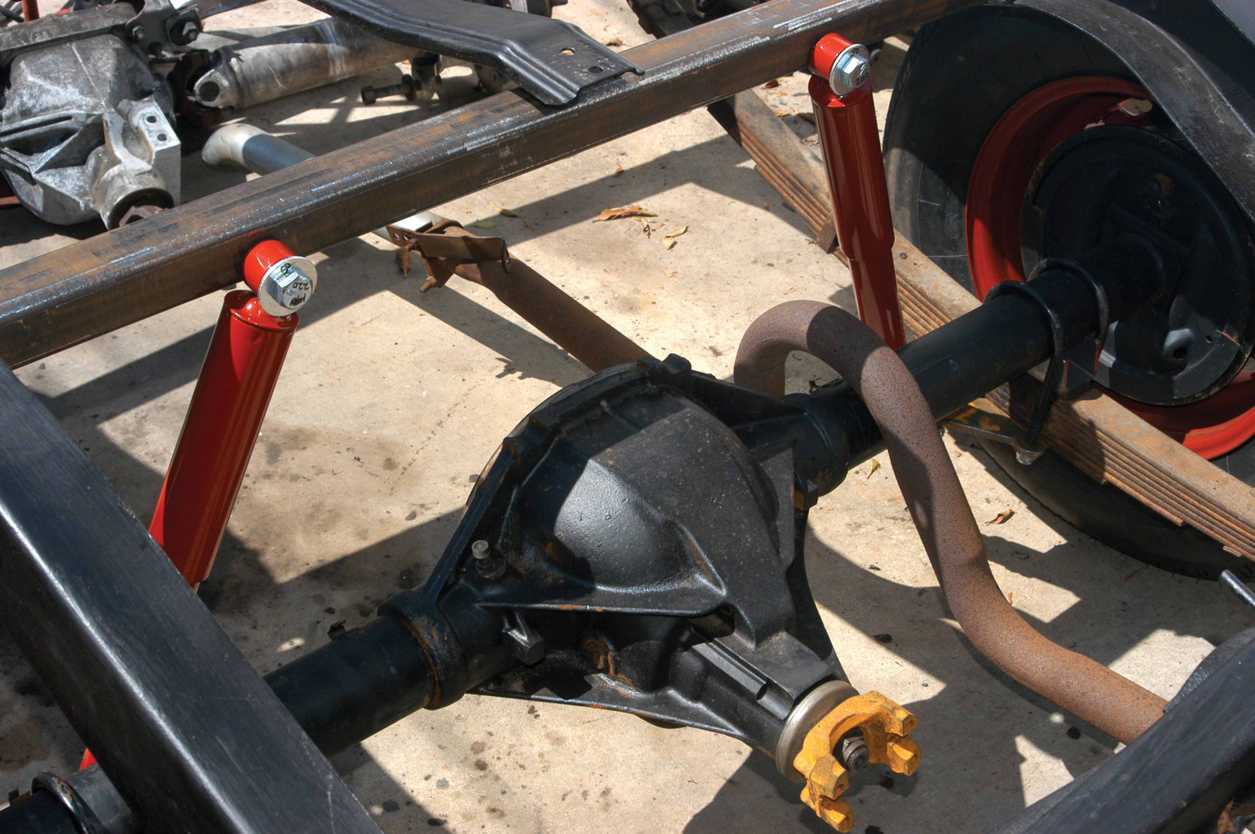
51a-b After the holes were drilled on both sides, the tubing was reinstalled in the frame and the shocks were bolted on.
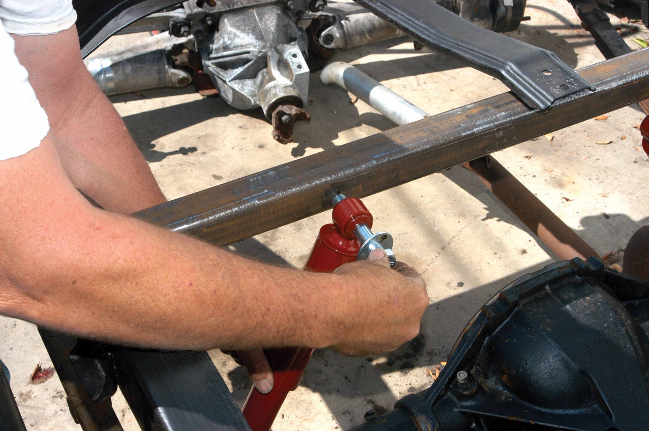
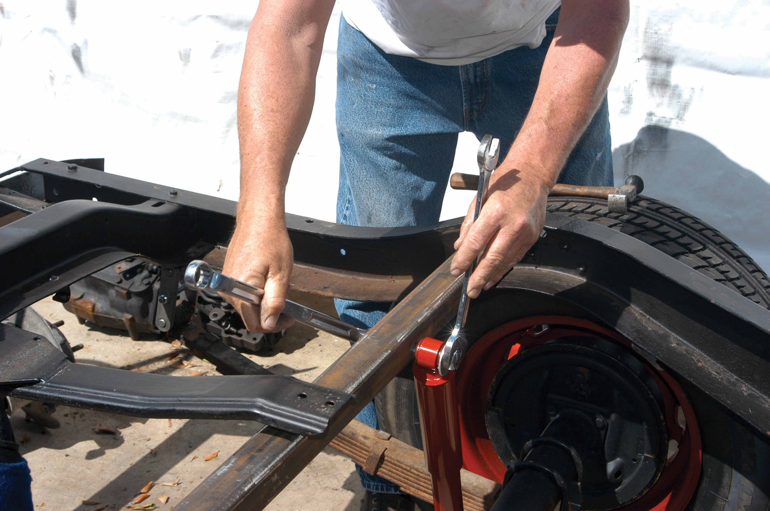
52 The upper shock bolt was tightened using a pair of large wrenches.
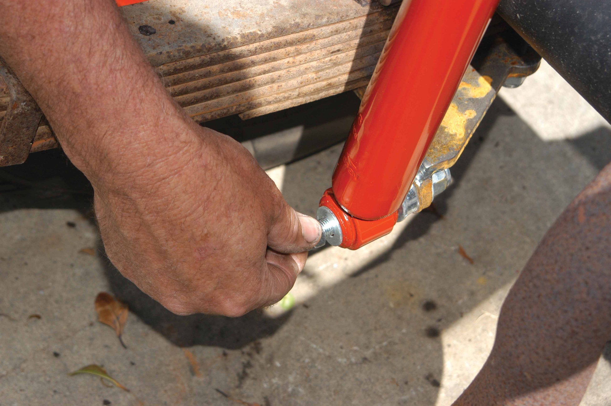
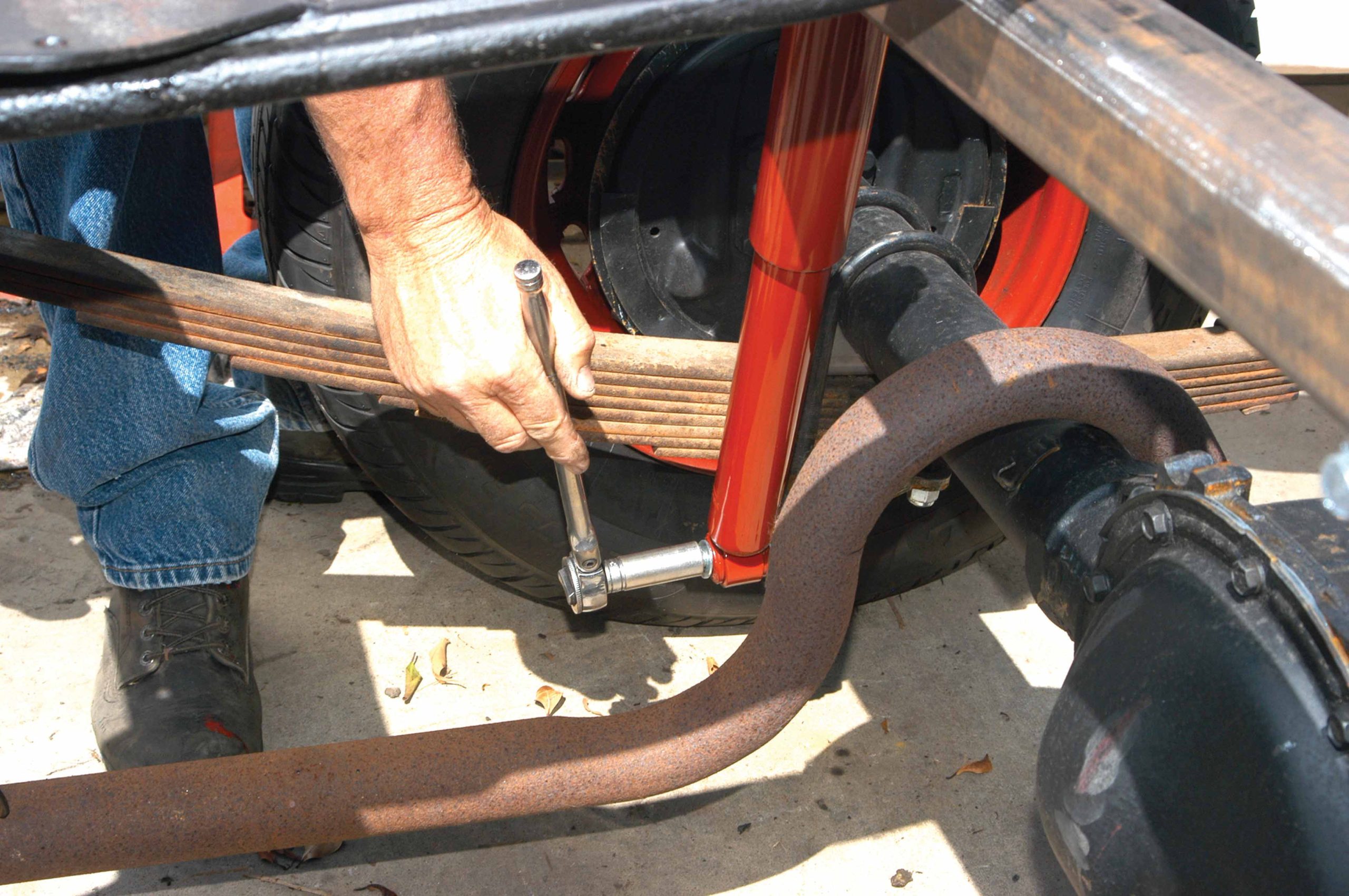
53 The lower shock nut was installed with a ratchet and deep socket.
54 After the upper and lower shock bolts were connected, the location of the tubing was precisely measured and adjusted to make sure it was square in the frame.
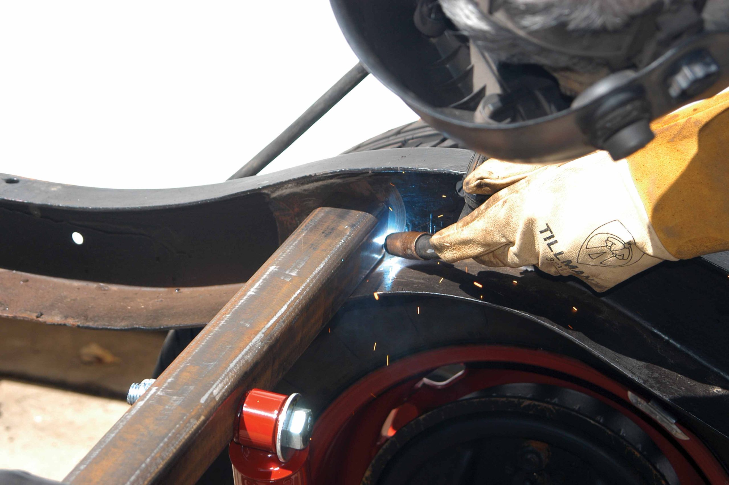
55 After the tubing was set correctly, it was finish-welded to the frame, as seen here.
56a-b The differential looks like it was factory installed, and with the rebuilt stock springs, it should ride just as it did when it rolled out of the factory